B+S NC Series User guide

1
INSTALLATION, OPERATING AND SERVICING INSTRUCTION MANUAL
NC Series Commercial Noodle Cooker/Pasta cooker/Soup
warmer/CF Steamer
Model No’s.: NC –6 –R/S –2RP/SP –CF –YC
Approval No.; GMK 10682
B&S Commercial Kitchens Pty Ltd
57 Plateau Road Reservoir VIC 3073 AUSTRALIA
Tel: +61 3 9469 4754 Fax: +61 3 94694504 Web: www.bscommercialkitchens.com
Please ensure this booklet is kept in a safe and prominent location for future reference.
The reproduction on or copying of any part of this booklet via any means is strictly forbidden unless agreed to in writing by the
manufacturer.
Owing to continual product development and improvements to its products, B&S Commercial Kitchens Pty Ltd reserves the right to
change the product specifications and design without prior notice.

2
Table of Contents
INSTALLATION, OPERATING AND SERVICING INSTRUCTION MANUAL....................1
NC Series Commercial Noodle Cooker/Steamer.........................................................1
Product Specifications & Introduction ............................................................................3
Table 1: Nominal Terminal Input Rates & Injector Sizes ...................................................................................3
Table 2: Standard Model General Information...................................................................................................4
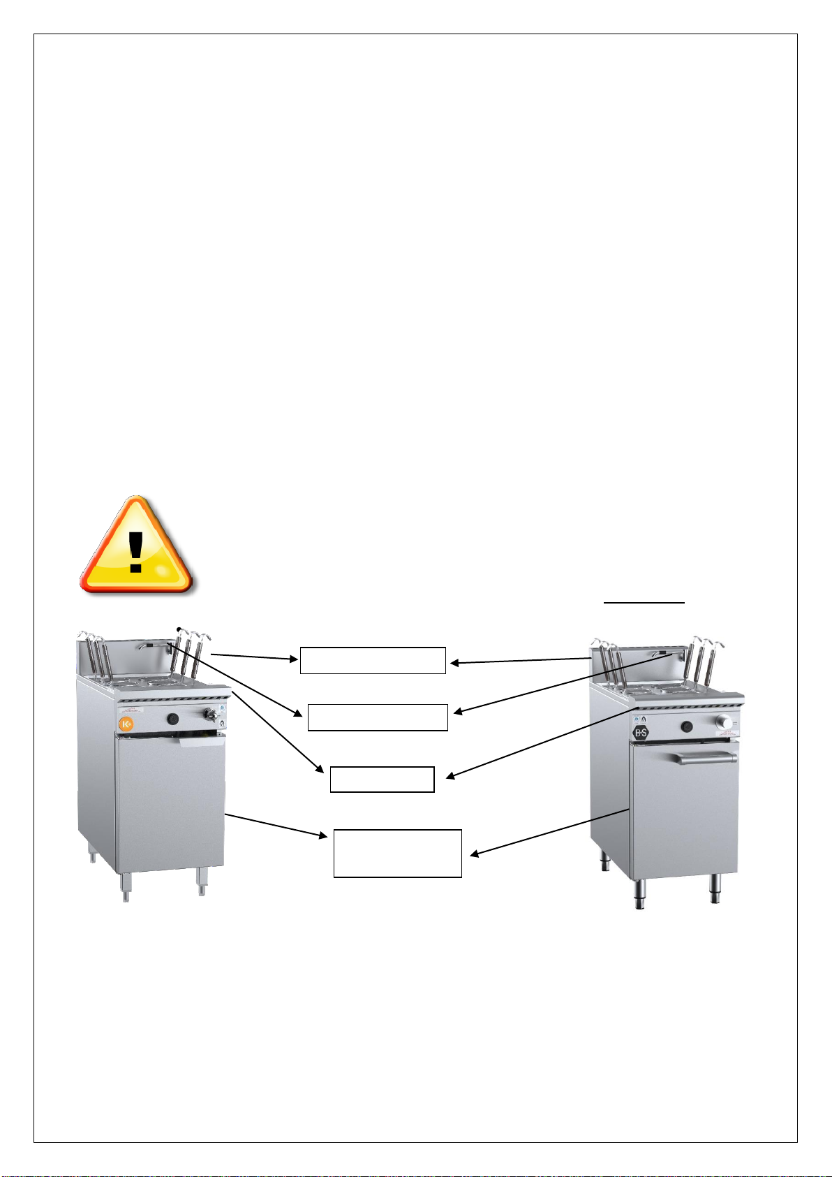
Figure 1: Plumbing Connections -Black & Verro NC-6......................................................................................4
Table 3: Plumbing Connections.........................................................................................................................4
Figure 2: Plumbing Connections -Black & Verro NC-9......................................................................................5
Table 4: Plumbing Connections.........................................................................................................................5
IMPORTANT WARNINGS..................................................................................................5
Installation Instructions ....................................................................................................6
Regulations ........................................................................................................................................................6
Data Label..........................................................................................................................................................6
Ventilation...........................................................................................................................................................6
Combustible Surfaces........................................................................................................................................7
Plinth Mount Models...........................................................................................................................................8
Gas Connection .................................................................................................................................................8
Pressure Test Point............................................................................................................................................8
Water Connection ..............................................................................................................................................8
Burner Adjustment .............................................................................................................................................8
Before Leaving - Commissioning.......................................................................................................................8
Operating Instructions ......................................................................................................9
IMPORTANT WARNING!....................................................................................................9
Lighting Instructions..............................................................................................................................10
Shutdown Procedure.............................................................................................................................10
Boil Out Procedure................................................................................................................................10
Laundry Arm Activation.........................................................................................................................10
IMPORTANT NOTE!........................................................................................................................................10
Maintenance and Care..........................................................................................................................10
Servicing Instructions.....................................................................................................11
Abnormal Operation..............................................................................................................................11
Panel Removing....................................................................................................................................11
Controls.................................................................................................................................................11
Thermostat............................................................................................................................................12
Pilot Assembly.......................................................................................................................................12
Piezo Assembly.....................................................................................................................................12
Burners..................................................................................................................................................12
Gas Valve..............................................................................................................................................12
Table 4: Troubleshooting .................................................................................................................................12
STANDARD WARRANTY CONDITIONS .........................................................................13

3
Product Specifications & Introduction
We are confident that you will be delighted with your B&S Noodle Cooker, and that it will become the backbone of
your kitchen. To ensure you receive the utmost benefit from your new B&S appliance, there are two
important things you can do.
1. Ensure you read this booklet carefully and carefully follow the instruction given. Ensure that this booklet is
kept in a safe and prominent location for future reference.
2. Should you be ensure of any aspect of the operation/performance, servicing and installation of the appliance,
please contact your B&S dealer immediately. In most instances a phone call could answer your question.
Table 1: Nominal Terminal Input Rates & Injector Sizes
Gas Type
Injector Size (mm)
MJ/h
per pan
Test Point
Pressure
NC-6
(All 450mm wide units)
Natural Gas
Propane Gas
1.40 mm
0.90 mm
70
75
1.00 kPa
2.60 kPa
NC-9
(All 600mm wide units)
Natural Gas
Propane Gas
1.65 mm
1.00 mm
95
90
1.00kpa
2.60kpa
Appliance Name:
NC Series Noodle Cooker/Pasta cooker/Soup warmer/CF steamer
This appliance may be brandedas B+S Black ,Verro and K plus
ManufacturedBy:
Certificate Holder:
B&S Commercial Kitchen s Pty Ltd
57 Plateau Road
Reservoir Victoria 3073
Tel; + 61 3 9469 4754 Fax: +61 3 9469 4504
E-mail: info@bscommercialkitchens.com
ModelNumber/s:
Suppliedinvariousconfigurations.
Howtoreadmodelnumbers;
(K)(V)NC-6 –R/S–2RP/SP–CF–YC-P
NC-6 –Noodle Cooker (All Models)
R/S: No of Round/Square Noodle/Pasta Baskets per Pan
2 –Two Round/Square Baskets
4 –Four Round/Square Baskets
6 –Six Round/Square Baskets
RP/SP: Number of Rectangular/Square Pots per Pan
1 –One Rectangular Pan
2 –Two Rectangular Pan
3 –Three Rectangular Pan
CF –Cheung Fun Steaming Tray
YC –Yum Cha Steaming Tray
P –Plinth Mount
V at the beginning indicates Verro and K indicates K plus
E.G. NC4-1RP
Isnoodlecookerwithtankprovisionsforfourroundbasketsandonerectangularpot.
ApprovalNumber:
GMK10682
GasType/s:
NaturalGas &PropaneGas

4
Please note that the minimum gas inlet pressure should be at least 1.13KPa (Natural Gas) and 2.75KPa
(Propane). Gas pressure must be checked when all other equipment on the same line is turned ON high.
Table 2: Standard Model General Information
Weight
(kg)
Overall Height
(mm)
Overall Depth*
(mm)
Overall Width*
(mm)
NC-6
NC-9
VNC-6
VNC-9
100
130
100
130
1,300
1300
1030
1030
840
840
800
800
460
600
460
600
*
Denotes Minimum
Overall Dimensions –Custom made appliances
Height overall splashback : 950mm - 1,300mm + adjustable legs.
Height Plinth Mount : 980mm.
Width : 1,840mm minimum with 4 pans. (NC-6)
2400mm minimum with 4 pans ( NC-9)
Depth : 800mm minimum.
Figure 1: Plumbing Connections -Verro NC-6 (800 deep)
Table 3: Plumbing Connections
Connection
Position from
Floor
(mm)
Position from
Rear of Appliance
(mm)
Position from
LHS/RHS edge
of Appliance
(mm)
Water Inlet (WI)
Gas Inlet (GI)
½” Copper
575 (+/-5)
640 (+/-5)
180 (+/-5) LHS
¾” male BSP
215 (+/-5)
455 (+/-5)
65 (+/-5) LHS
Over Flow (OV)
1” drain hose
605 (+/-5)
640 (+/-5)
130 (+/-5) LHS
Drain
1” BSP female
295 (+/-5)
500 (+/-5)
230 (+/-5) LHS
Plinth mount models have connections 170 mm lower.

5
Figure 2: Plumbing Connections -K plus and Verro NC-6 (840 deep unit)
Table 4: Plumbing Connections
Connection
Position from
Floor
(mm)
Position from
Rear of Appliance
(mm)
Position from
LHS/RHS edge
of Appliance
(mm)
Water Inlet (WI)
Gas Inlet (GI)
½” Copper
410(+/-5)
630 (+/-5)
90 (+/-5) LHS
¾” male BSP
230 (+/-5)
615 (+/-5)
70 (+/-5) RHS
Drain
1” male pipe
165 (+/-5)
540 (+/-5)
225 (+/-5) LHS
IMPORTANT WARNINGS
THIS APPLIANCE SHALL ONLY BE INSTALLED/SERVICED BY AN
AUTHORISED INSTALLER.
THIS APPLIANCE MUST BE INSTALLED IN ACCORDANCE WITH THE
SPECIFIED INSTRUCTIONS AND SPECIFICATIONS.
IMPROPER INSTALLATION OR OPERATION OF THIS APPLIANCE MAY
RESULT IN PRODUCT FAILURE WHICH MAY LEAD TO PROPERTY
DAMAGE, PERSONAL INJURY OR DEATH.
CAUTION MUST BE TAKEN WHEN OPERATING THIS APPLIANCE TO
MINIMISE RISK OF FIRE. THE APPLIANCE MUST NOT BE LEFT ON
UNATTENDED.
REGULAR INSPECTIONS BY AN AUTHORISED SERVICE PERSON ARE STRONGLY RECOMMENDED TO ENSURE
PROPER AND SAFE FUNCTIONING OF THIS APPLIANCE.
AFTER ANY SERVICING OR ADJUSTING OF GAS CONNECTED COMPONENTRY, GAS LEAK TEST MUST BE
CARRIED OUT TO ENSURE THERE ARE NO GAS LEAKING HAZARDS.
NEVER STORE ANY FLAMMABLE LIQUIDS/VAPOURS IN THE VACINITY OF THIS APPLIANCE. NEVER SPRAY
AEROSOLS IN THE VICINITY OF THIS APPLIANCE WHILE IT IS IN OPERATION.
ENSURE ANY TRANSIENT PROTECTION IS REMOVED BEFORE INSTALLING THE APPLIANCE ENSURING ANY
POSSIBLE DAMAGE TO THE APPLIANCE OR COMPONENTS/PARTS THAT MAY HAVE BEEN SUSTAINED
DURING TRANSPORTATION IS REPORTED TO THE MANUFACTURER. ANY DAMAGE INCURRED DURING
TRANSPORTATION MUST BE REPORTED IMMEADIATELY TO THE MANUFACTURER AND IT IS

6
RECOMMENDED THE APPLIANCE IS NOT INSTALLED UNTIL FURTHER INSTRUCTIONS FROM
MANUFACTURER.
THIS APPLIANCE IS NOT INTENDED TO BE USED IN A MARINE ENVIRONMENT.ENSURE APPLIANCE IS
INSTALLED IN A STABLE POSITION.
FAILURE TO FOLLOW THE INFORMATION PROVIDED IN THIS BOOKLET WILL VOID THE B&S WARRANTY
AND MAY RESULT IN DAMAGE TO EQUIPMENT OR INJURY TO PERSONNEL
Please note that checking and adjusting of burner pressures on commercial catering appliances is an obligation of
gasfitters.
The relevant legislation is as follows from the Plumbing Regulations 2008 administered by the Victorian Building
Authority:
Gas fitting work defined
(1) Gas fitting work is the construction, installation, replacement, repair, alteration, maintenance, testing or
commissioning of any pipe, appliance, flue, fitting, apparatus, control or other item that is involved with the
supply or use of gas and that is fitted downstream of the outlet of a customer billing meter or a consumer's
gas storage container
As per AS/NZS5601.1, clause 6.11.1, this gas appliance must be commissioned by a suitably authorized person
who;
(a) Installed the appliance when gas is available at the time of installation; or
(b) Makes gas available to the appliance if gas was not available at the time of installation
As per AS/NZS5601.1, clause 6.11.3, the commissioning of this appliance shall take full account of special design
features, the manufacturer’s instructions and the appliance safety requirements.
As per AS/NZS5601.1, clause 6.11.4, the commission of this appliance shall include all of the following;
(a) Testing and purging of the appliance and installation as appropriate.
(b) Checks to ensure the appliance is in safe working order.
(c) Ignition of each burner of the appliance and where necessary adjustment, in accordance with the
manufacturer’s instructions.
(d) Testing of flue performance.
(e) Testing of all safety devices for correct operation.
(f) Instruction of the consumer, where available, on the safe and correct operation of the appliance and any
auxiliary equipment.
(g) Handing of the appliance operating instructions to the consumer, or if the consumer is not present, leaving
the instructions in a suitable location on the premises.
Installation Instructions
Regulations
The appliance must be installed only by authorised persons and in accordance with the manufacturer’s installation
instructions, local gas fitting regulations, municipal building codes, AS 5601 –Gas Installations and any other health
and safety regulations, local authority, gas, electrical any other statutory regulations.
Data Label
The data label is located behind the door at the top left corner. This appliance is suitable for Natural Gas and LPG.
Please ensure that the gas supply matches the Data Label ensuring that the gas supply is correct for the appliance
being installed and that adequate supply pressure and volume is available –refer to appliance data plate for MJ/h
consumption, injector sizes of main burners etc.
Ventilation
The appliance should always be installed under an extraction hood. Ventilation must be in accordance with AS5601 -
Gas Installations. In general, the appliance should have adequate ventilation for complete combustion of gas, proper
flueing and to maintain temperature of immediate surroundings within safe limits.

7
The appliance shall be installed with an exhaust system comprising a hood and duct system. The hood shall be made
of a material which is impervious to fat, grease and vapour. It shall be constructed so it can be readily and efficiently
cleaned. Its inside faces shall be smooth and free of obstructions and all joints shall be grease tight.
The hood shall be located so as to effectively ventilate the noodle cooker and shall extend at least 150 mm beyond
the perimeter of the unit. The exhaust duct system shall be adequately sized and shall not get connected to any
other ventilating or exhaust system.
As suitable grease trap shall be provided to prevent grease vapour entering the exhaust system and shall be located
to avoid constituting a fire hazard and be readily accessible for regular cleaning.
(please refer to AS/NZS 5601 clause 6.10.2.2 to verify clearances for ventilation.)
B&S units can be installed in a domestic environment provided the installation is strictly in accordance with
the manufacturer’s instructions and as per the AS/NZS5601.1 (please refer to the latest version when
released). The installation of the unit must comply with clauses 6.2.4, 6.10.2 and 6.10.1.15 and an exhaust
system shall be installed according to AS1668.1 and AS1668.2 interlocked to the gas supply. B&S shall not
be responsible for any unauthorized and/or non-compliant installations and will void the warranty.
Combustible Surfaces
Clearances to combustible surfaces must be in accordance with AS/NZ 5601- Gas Installations, clause 5.12.4.5.
Install on a flat/level, solid, fire resistance floor. Where the floor is not fire resistant, a fire resistant material shall be put
under the appliance which shall have a fire resistance rating at least equal to that of 10mm millboard. The material
shall extend at least 50mm beyond the edge of the appliance.
Leave a clearance of at least 200mm between the appliance and any combustible surface.
Leave clearance of at least 500mm from the front of the noodle cooker for services.
Please refer to table 6.9 and 6.10 in AS 5601.1. clause 6.10.2.2 and 6.10.2.3. Table 6.10 (2013 version) is given
below. (Please refer to the latest version when released)
MINIMUM CLEARANCE AROUND COOKING SURFACE AREA
The clearance to combustible surfaces from commercial catering equipment shall be as specified in the appliance
manufacturer’s instructions and shall not be less than the clearance specified in the table below.
Cooking surface area
Minimum clearance in mm
A
Above the cooking surface of a gas appliance
600
B
Subject to C from a cooking surface area having an open
flame cooking appliance and no means of preventing
cooking vessels from overhanging the edge of the gas
appliance
250
C
From the side of a cooking appliance where the
combustible surface is at least 100mm below a cooking
surface area
50
D
From a gas appliance flue way or rear of the gas appliance
with a splashback
50
E
From the rear or side of a gas appliance which is not an
open flame gas cooking appliance
50
Notes:
1. The cooking surface area is defined as being that part of the gas appliance where cooking normally takes
place and does not include those parts of the gas appliance containing control knobs.
2. These clearances do not apply where an adjacent surface is of a non-combustible material or is combustible
but protected with a fire-resistant material. The fire-resistant material may be covered by ceramic tiles or
stainless steel to meet appropriate requirements relating to health protection.
3. Care should be taken where a combustible surface is covered by a non-combustible material for example,
covering a combustible surface with stainless steel will not prevent heat transfer, and in some circumstances
hazardous situation could arise.

8
Plinth Mount Models
To plinth mount remove the legs and replace it with the plinth kit provided by the manufacturer. Allow the the unit on a
concrete slab which should be the width of the appliance and 700mm deep. The height of the slab is determined by
the manufacturer.
Gas Connection
The gas connection is ¾” BSP female elbow and is situated at the front of the appliance above the base of the frame.
This appliance is available in models for fixed installation or in models with wheels/castors
The appliance can be connected with rigid pipe as specified in AS/NZ 5601. For fixed installation models we
recommend connection with 20mm copper tube and a certified isolating ball valve. For models fitted with
wheels/castors an Australian certified stainless steel braided flexible hose of adequate internal diameter must be
used. The fitting of the hose must comply with the relevant sections of gas installation code AS/NZS 5601. A
restraining chain or wire must be fitted. We recommend a maximum length of 1.5 m for the flexible hose. The
castors will be installed only on the rear of the unit and front of the unit will have legs to hold the unit in place. An
Australian certified isolating ball valve must also be fitted.
We strongly do not recommend the usage of flexible hoses for gas inlets when the unit is plinth mounted.
BEFORE CONNECTING NEW PIPE TO THIS APPLIANCE, THE PIPE MUST BE BLOWN OUT THOROUGHLY TO
REMOVE ALL FOREIGN MATERIAL. FOREIGN MATERIAL IN THE BURNER AND GAS CONTROLS WILL
CAUSE IMPROPER AND DANGEROUS OPERATION.
Connect to gas.
Pressure Test Point
All appliances that are dispatched from our factory are tested and adjusted according to the specifications for the
required gas type. A combination control valve is used and pressure can be checked and adjusted on the valve.
The test point pressure should be adjusted to 1.00 kPa –Natural gas or 2.60 kPa –LPG with the burners operating at
maximum.
Water Connection
The water connection is 15mm copper and is situated at the front of the appliance in the main body frame. The
number of water inlets varies to client’s particular needs. Water isolation valves are fitted to all water inlets. Ensure
water is flushed through before final connection.
Water waste outlet is located on the centre of the appliance at the bottom of the tank (1” female)of the appliance.
The water inlets and water drains should be connected with rigid copper pipes. Plastic/PVC piping should not be
used for connection of waste outlet which will void warranty if done so. Please ensure water keeps running
through the laundry arm while in operation to prevent the laundry arm cracking due to heat.
Burner Adjustment
The burners do not require any adjustments.
Note: If any problems are experienced in maintaining the burners, your local service agent should be contacted.
Before Leaving - Commissioning
Check all connections for gas leaks with soap and water. Do not use a naked flame for detecting leaks.
Ignite the pilot and main burners as prescribed below to ensure correct operation of gas valves, burners and ignition.
When satisfied with the operation of the appliance, please instruct the user on the correct method of operation.
Ensure that this instruction manual is left with owner of the appliance.
A. Set thermostat to lowest setting
B. Turn valve knob such that indicator knob points to ‘OFF’ (solid circle) position and allow 5 minutes for any gas
in combustion chamber to escape (propane gas being heavier than air, may require forced ventilation). Note:

9
If knob is ‘ON’ (flame) position, turn anti-clockwise to ‘PILOT’ (spark) position. Then depress knob and turn to
‘OFF’ position.
C. Turn valve knob clockwise so indicator points to ‘PILOT’ position.
D. Then light the pilot using the piezo while depressing the valve knob.
E. Keep knob fully depressed for thirty seconds.
F. Release valve knob. Pilot flame should continue to burn. Observe pilot is established. If pilot goes out when
knob is released, repeat steps A to Fallowing more time for thermocouple or pilot generator to heat up.
G. When pilot stays alight, turn on the gas valve and then operation of the burner may be given over to
thermostat by turning clockwise
H. Set thermostat to desired temperature.
In the event the appliance fails to operate correctly, check the following;
1. Data plate to ensure correct gas type and pressure (adjust if necessary).
2. Injector sizes –check against data plate and installation manual.
3. View pilot size and adjust if required.
In case appliance fails to operate correctly after all checks have been carried out, pleased contact;
B&S Commercial Kitchens Pty Ltd
57 Plateau Road
Reservoir VIC 3073
Tel.: + 61 3 9469 4754 Fax.: + 61 3 9469 4504 E-mail: info@bscommercialkitchens.com
Operating Instructions
WARNING!
•DO NOT spray aerosols in the vicinity of this appliance while it is in operation.
•DO NOT store or use flammable liquids or items in the vicinity of this appliance.
•Prior to lighting, smell area surrounding the appliance for gas (please note that as some gas
types are heavier than air, we recommended the operator to also smell the floor around the
appliance).
•In the event you smell gas: DO NOT light any appliance. DO NOT touch/ operate any
electrical switch or phone in your building. Call local gas supplier immediately and follow their
instructions.
•
IMPORTANT WARNING!
ALWAYS ENSURE NOODLE COOKER PAN HAS WATER IN IT WHEN MAIN BURNERS AND PILOT LIGHT ARE
ALIGHT.
To ensure noodle cooker pan is clean from any contamination resulting from the appliances manufacture,
shipping and installation, the noodle cooker pan must be boiled out before first use.
NEVER LEAVE THE APPLIANCE UNATTENDED DURING THE BOIL-OUT PROCESS. IF THE BOIL-OUT
SOLUTION OVER BOILS, IMMEDIATELY TURN THE NOODLE COOKER OFF AND LET THE SOLUTION COOL
FOR A FEW MINUTES BEFORE RESUMING THE PROCESS.
Splashback
Laundry arm
Hob
Gas Controls
behind door

10
BEFORE LIGHTING THE NOODLE COOKER, MAKE SURE THE NOODLE COOKER IS ‘OFF’ AND THE NOODLE
COOKER PAN DRAIN VALVE(S) IS/ARE CLOSED. NEVER ALLOW BURNER TO OPERATE WITH TANK EMPTY.
LIGHT ONLY WHEN THE WATER IS AT THE MINIMUM OPERATING WATER MARK LOCATED ON REAR
PANEL OF PAN (WHEN LOOKING INTO PAN STANDING IN FRONT OF THE APPLIANCE).
Lighting Instructions
A. Set thermostat to lowest setting
B. Turn valve knob such that indicator knob points to ‘OFF’ (solid circle) position and allow 5 minutes for any gas
in combustion chamber to escape (propane gas being heavier than air, may require forced ventilation). Note:
If knob is ‘ON’ (flame) position, turn anti-clockwise to ‘PILOT’ (spark) position. Then depress knob and turn to
‘OFF’ position.
C. Turn valve knob clockwise so indicator points to ‘PILOT’ position.
D. Then light the pilot using the piezo while depressing the valve knob.
E. Keep knob fully pressed for thirty seconds.
F. Release valve knob. Pilot flame should continue to burn. Observe pilot is established. If pilot goes out when
knob is released, repeat steps A to Fallowing more time for thermocouple or pilot generator to heat up.
G. When pilot stays alight, turn on the gas valve and then operation of the burner may be given over to
thermostat by turning clockwise
H. Set thermostat to desired temperature.
Shutdown Procedure
A. Set thermostat to lowest setting.
B. Turn gas cock knob such that indicator knob points to ‘OFF’ (solid circle) position and allow 5 minutes for any
gas in combustion chamber to escape (propane gas being heavier than air, may require forced ventilation).
C. Observe pilot frame is extinguished.
Boil Out Procedure
1. Prior to lighting burner, ensure noodle cooker drain valve is closed.
2. Fill noodle cooker pan with a mixture of cold water and dishwashing detergent up to the bottom of the water
level line in the pan.
3. Operate the appliance as described in LIGHTING PROCEDURE above.
4. Simmer the solution for approximately one hour and turn off main burner and allow solution to cool.
5. Add approximately 5 litres of cold water into the pan and stir.
6. Open drain valve and drain the solution into a suitable container and then clean the pot thoroughly.
7. Close drain valve and rinse the fryer pan a couple of times by filling the pan with clean water and draining.
8. Dry the pan thoroughly with a clean/dry towel.
Laundry Arm Activation
The water tank must be filled with water whenever the burners are in use to prevent the base of the pan from buckling
and distorting. To activate;
1. Locate spindle on front panel.
2. Turn spindle anti-clockwise to activate water.
3. Adjust as necessary.
4. Turn spindle clockwise to de-activate water.
IMPORTANT NOTE!
A SMALL AMOUNT OF TRICKLING WATER MAY BE REQUIRED TO RUN INTO THE PAN WHILST IN
OPERATIONS TO ENSURE ADEQUATE WATER SUPPLY TO THE TANK, ENSURE EXCESS STARCH CREATED
DURING COOKING PROCESS EXITS VIA THE OVERFLOW PIPE AND ENSURE WATER PURITY.
Maintenance and Care
To ensure longevity and continued performance efficiency of your appliance, a good cleaning and maintenance
program is paramount. In general, the use of steel wool abrasive cloths/cleaners/powders should not be used to
clean this appliance.
Daily Checks & Service

11
•Look for any foreign materials in burner area, leaks, damaged knobs and any other signs that the unit is not
ready and safe for operation. Inspect burner area and ensure pilots are in position near the burner, and that
the pilot flame when ignited is blue in color and approximately 20-40mm in length. If fitted with thermocouple,
ensure pilot flame is in contact with it. Call the manufacturer if you see any problems. Always ensure that
area surrounding pilot and thermocouple is clear of any fats, oils or foodstuffs.
•Clean the exterior surfaces of the unit with a clean, damp cloth soaked with mild detergent to remove any
food stuffs, oils, dust and any other materials.
•Ensure the overflow water drain (located in gutter) is cleared of any food stuffs during operation of the
appliance and on completion of use of the appliance.
Yearly Checks & Service
•The appliance should be inspected and adjusted periodically by a qualified service person as part of
any kitchen maintenance program.
•B&S recommends that this appliance is inspected at least annually by an authorised service
technician as follows:
oInspect the unit inside-out for excessive build-up of any fats, oils and foodstuffs.
oInspect that the burners and other components (i.e. pilots, thermocouples, etc.) are in good condition
and functioning properly.
oInspect all gas connections for leaks and ensure all connections are tightened properly.
oEnsure burner manifold pressure is in accordance with that specified on the data plate of the
appliance.
oInspect all gas connections for leaks and ensure all connections are tightened properly.
In case of difficulties, contact B&S Commercial Kitchens Pty Ltd or their authorised service agent.
Servicing Instructions
WARNING!
•Servicing shall be carried out by authorized personnel only. Failure to do so will void the B&S
warranty and may result in damage to equipment or injury to personnel.
•Before commencing any disassembly/ assembly of gas controls, please ensure the gas
supply is turned off (isolated).
FAILURE TO DO SO WILL VOID B&S WARRANTY AND MAY RESULT IN DAMAGE TO EQUIPMENT OR INJURY
TO PERSONNEL.
Abnormal Operation
Any of the following are considered to be abnormal operation and may require servicing;
•Incomplete ignition of burner/burner failing to keep alight.
oCheck burner is not blocked.
•Yellow tipping of the burner flame.
oCheck aeration of burner.
•Gas valves which are difficult to turn.
Panel Removing
1. It is not necessary to remove any side or back panels for servicing the unit.
2. To remove the front panel, it will be necessary to pull off the thermostat control knob then undo the two
screws holding the panel to the front hob section.
Controls
If gas control fails to operate, check the following;
1. The thermocouple is in the pilot flame. The thermocouple must be hot in order to generate energy to operate
an electromagnetic system to lift and maintain open the control valve.
2. To do so, it is necessary to generate approximately 650 milli-volts. If not functioning correctly, the
thermocouple should be replaced.
3. Check both main and safety thermostats switching systems. If thermostat is malfunctioning, it should be
replaced.

12
Thermostat
1. Pull thermostat knob off and unscrew thermostat from control panel.
2. Remove control panel.
3. Remove both terminals from the thermostat.
4. Remove thermostat capillary gland and remove thermostat bulb.
5. To fit new thermostat, reverse the above procedures
Pilot Assembly
1. Undo the two screws holding the pilot bracket assembly on the burner bar.
2. Gently pull the pilot assembly bracket down and outwards.
3. To change thermopile
a. Undo locking screw holding thermopile to pilot assembly bracket and gently pull the thermopile down.
b. Undo terminal screws on located on ‘TH TP’ and ‘TP’ on main gas valve.
c. Replace with new thermopile and assemble in reverse order.
4. To change thermocouple
a. Undo locking screw holding thermocouple to pilot assembly bracket and gently pull the thermocouple
down.
b. Undo thermocouple screw located in the main gas valve.
c. Replace with new thermocouple and assemble in reverse order.
5. To change new pilot assembly
a. Follow steps 1 and 2.
b. Undo the two screws on the pilot mounting bracket and pilot bracket.
c. Follow procedures 3. A. and 4. A. listed above.
d. Remove piezo lead from piezo.
e. Undo pilot gas flexible tube.
f. Change pilot assembly over and reassemble in reverse order.
Piezo Assembly
1. To change piezo ignitor
a. Undo the piezo screw located on the back of the piezo ignitor located close to the valve
b. Gently remove piezo lead from rear of piezo ignitor
c. Replace piezo ignitor and replace in reverse order
2. To change piezo lead
a. Gently remove piezo lead from rear of piezo ignitor.
b. Gently remove piezo ignitor lead from pilot assembly
c. Replace with new lead and assemble in reverse order.
Burners
1. To change/service burner (ensure burner is cool to prevent injury to service person)
a. Remove the 4 wing nuts from the burner mount bracket
b. Remove the pilot assembly which is attached on the burner bracket
c. Slowly drop the burner and take it out from the back of the unit.
Gas Valve
1. To remove/change/service main gas valve.
a. Undo the flexi that goes into the burner
b. Undo the bolted clip at the side of the unit.
c. Then remove the elbow on the right side of the valve by undoing 4 screws.
d. Reassemble it in the reverse way
Table 4: Troubleshooting
FAULT
POSSIBLE CAUSE
CHECKS
Pilot light not igniting
Blockage of pilot
Adjustment of pressure from flame failure
control
Check pilot injector is not blocked as
described in servicing instructions –pilot
and flame safeguard
Check gas pressure to pilot as described
under servicing instructions –adjustments
Pilot light not establishing
Check connection of the thermocouple to

13
Positioning of thermocouple
Faulty thermocouple
Faulty flame failure control valve
the control is not loose.
Adjust positioning of thermocouple to
ensure pilot flame is hitting thermocouple
Contact manufacturer or authorised
service agent
Contact manufacturer or authorised
service agent
Pilot established, main burner
not lighting
Faulty thermocouple
Faulty Thermopile
Faulty flame failure control valve
Contact manufacturer
Telescopic laundry arm
constantly running (on
water/deck cooled wok tables)
Worn tap washer
Change washersintap assembly.
Contact manufacturer or authorised
service agent
To obtain further service information concerning this appliance, please contact;
B&S Commercial KitchensPty Ltd
57 Plateau Road
Reservoir VIC 3073
Tel.: + 61 3 9469 4754 Fax.: + 61 3 9469 4504 E-mail: info@bscommercialkitchens.com

14
STANDARD WARRANTY CONDITIONS
B&S Commercial Kitchens Pty Ltd of 57 Plateau Road, Reservoir, Victoria (hereinafter called ‘B&S’) undertakes by
this warranty, that B&S or its agent will pay for the cost of labour and parts which B&S or its agent find defective for:
K+ Range - eighteen (18) months from date of installation/hand over for projects.
B+S Black Range –twenty four (24) months from date of installation/hand over for projects.
Verro Range –thirty six (36) months from date of installation/hand over for projects.
The liability of B&S under this warranty is limited to the repair or replacement of defective goods or components. All
other costs including, without limitation, cartage, carriage and installation shall be borne by the purchaser.
IMPORTANT
Prior to requesting a service call, please be sure that cooking equipment is being used and maintained in accordance
with the instruction manual provided with your cooking equipment. Please also be sure that your cooking equipment
has been installed in accordance with the manual by a qualified installer. All cooking equipment must be
commissioned by installer upon completion of installation. Failure of these procedures will result in non-warranty
service costs.
Warranty labour is supplied free of charge during business hours (8 a.m. to 4 p.m. AEDST) Monday to Friday.
Should warranty work be requested outside of our normal working hours, a labour charge will be applied
equivalent to a normal hour rate, with out of hours penalty rates. Penalty rates amount must be borne by the
purchaser. Claims for non-covered parts, no faults found, travel over 100km or other items outside our
standard terms and conditions will be chargeable. Note: Any extra time spent on site due to required
inductions etc. is not covered by warranty.
1. This warranty applies only for mainland Australia and Tasmania, and does not cover any service consequent upon
accident, alterations, misuse, fire, flood or act of God. Warranty for New Zealand is twelve (12) months parts and
labour for K+, B+S Black & Verro Ranges.
2. This warranty is valid only if the appliance has been installed in accordance with local regulations by a duly
authorised person, and the B&S installation instructions provided with the appliance. If in doubt, please contact
B&S or their representative for further information. No responsibility will be accepted for defects or damages by
improper installation, for changes to the product not authorised by B&S or for the operation outside the technical
specifications of the appliance.
3. This warranty is conditional upon the appliance being used in normal commercial catering operations.
4. This warranty is the only express warranty given by the Company. No person has authority to change or to add to
these obligations and liabilities.
5. The Company has the right to determine whether or not a fault is caused by faulty workmanship or material or that
any part is defective.
6. This warranty does not apply to any loss suffered through or resulting from the non-operation or the ineffective
operation of the cooking appliance or any part of the cooking appliance.
7. This warranty does not extend to goods and components thereof manufactured either entirely or substantially of
glass or similar substances, light globes, infrared or quartz tubes and electrical controls or elements.
8. While the goods are in custody of the seller for investigation or repair, they shall be at the risk of the purchaser
and no liability shall attach to the Company, its servants or agents for any damage occasioned to, or loan of, the
goods whatsoever.
9. All warranties are non-transferable and are only applicable to the original end user (purchaser).
10. All warranty work must be carried out by a B+S approved service technician.
The Purchaser must give notice to the Company immediately upon it becoming aware of the alleged defect
and in any event before the expiration of the appropriate warranty period.
B+S will endeavour to have a service technician on site for all warranty service requests within a 24 hour
period or by end of next business day at the latest. All warranty requests must be in writing by either lodging
a warranty request through B+S website or be emailing clientservices@bscommercialkitchens.com. Details of
installer such as contact name, business name, telephone number and license number must be provided to
avoid any delays.

15
11. Nothing in this warranty, however, shall be construed as affecting any rights you may have under the Trades
Practices Act or any other Commonwealth or State Legislation which gives you rights which cannot be modified or
excluded by agreement.
12. SPECIAL PROVISIONS –NOT COVERED BY WARRANTY
•Cleaning of spark and ignition sensors is not covered by warranty. Damage caused by oils, water and foodstuffs
falling into burners or pilots will not be covered under warranty.
•Cleaning of burners due to blockage of burner orifices caused by foodstuffs and/or oils is not covered by warranty.
•Breakage of pilot knobs, knee valve handles and knee wands are not covered under warranty.
•Thermocouples, piezo leads and ignitors are only covered by twelve (12) months parts and labour across K+, B+S
Black and Verro ranges.
•Seizure of gas cocks and knobs.
•Cleaning of blocked drains.
•Damage caused by lime scale and/or corrosion.
•Parts not supplied by B+S or a B+S authorised service technician.
•Damage caused by rodents and insects.
•Scheduled general maintenance.
•Normal wear and tear of parts
•Filters for DSK Deck Steamers
Additional costs are payable for:
Accommodation, cost of transport such as flights/ferries, poor access and waiting times.
B+S Commercial Kitchens
57 Plateau Road, Reservoir Victoria 3073 Australia
+61 3 9469 4754 | info@bscommercialkitchens.com | bscommercialkitchens.com
Other manuals for NC Series
1
This manual suits for next models
4
Table of contents
Other B+S Commercial Food Equipment manuals