B+S UFWWSP Series User guide

1
INSTALLATION, OPERATING AND SERVICING INSTRUCTION MANUAL
UFWWSP Series Commercial Stock Pot / Boiling Top
Model No’s.: UFW–W–D–SP-1/2/3–CB-LS
Approval No: GMK 10701
B&S Commercial Kitchens Pty Ltd
57 Plateau Road Reservoir VIC 3073 AUSTRALIA
Tel: +61 3 9469 4754 Fax: +61 3 94694504 Web: www.bscommercialkitchens.com
Please ensure this booklet is kept in a safe and prominent location for future reference.
The reproduction on or copying of any part of this booklet via any means is strictly forbidden unless agreed to in writing by
the manufacturer.
Owing to continual product development and improvements to its products, B&S Commercial Kitchens Pty Ltd reserves the
right to change the product specifications and design without prior notice.

2
Table of Contents
INSTALLATION, OPERATING AND SERVICING INSTRUCTION MANUAL....................1
UFWWSP Series Commercial Stock Pot / Boiling Top ...............................................1
Product Specifications & Introduction ............................................................................4
Table 1: Nominal Terminal Input Rates & Injector Sizes............................................................................... 4
Table 2: Standard Model General Information............................................................................................... 5
Figure 1: Plumbing Connections:- UFWWSPK-1 .......................................................................................... 5
Table 3: Plumbing Connections
...................................................................................................................... 5
Figure 2: Plumbing Connections:- UFWWSPD-1 .......................................................................................... 5
Table 4: Plumbing Connections
...................................................................................................................... 6
Figure 3: Plumbing Connections:- VUFWWSP-1 .......................................................................................... 6
Table 5: Plumbing Connections
...................................................................................................................... 6
IMPORTANT WARNINGS...................................................................................................6
Installation Instructions ....................................................................................................7
Regulations.............................................................................................................................. 7
Data Label ............................................................................................................................... 7
Ventilation................................................................................................................................ 8
Combustible Surfaces ............................................................................................................. 8
Gas Connection....................................................................................................................... 9
Pressure Test Point................................................................................................................. 9
Water Connection.................................................................................................................... 9
Before Leaving - Commissioning............................................................................................. 9
Operating Instructions ....................................................................................................10
IMPORTANT WARNING!..................................................................................................10
Lighting Instructions............................................................................................................... 11
Shutdown Procedure............................................................................................................. 11
Telescopic Laundry Arm –Manual Control (Water Cooled Models)..................................... 11
IMPORTANT WARNING!..................................................................................................11
Telescopic Laundry Arm Operation with Knee Valve –Where Fitted................................... 11
IMPORTANT WARNING!..................................................................................................11

3
Maintenance and Care .......................................................................................................... 11
Servicing Instructions.....................................................................................................12
Abnormal Operation .............................................................................................................. 12
Gaining Access to Gas and/or Water System....................................................................... 12
Removal of Burner for Service .............................................................................................. 13
Pilot and Flame Safeguard.................................................................................................... 13
Adjustments........................................................................................................................... 13
Servicing Wok Spout –Where Fitted..................................................................................... 13
Servicing Knee Valve –Where Fitted.................................................................................... 13
Gas Type Conversion............................................................................................................ 13
Table 5: Troubleshooting ............................................................................................................................. 14
STANDARD WARRANTY CONDITIONS .........................................................................15

4
Product Specifications & Introduction
Appliance Name: UFWWSP Series Commercial Stock Pot Table
This appliance may be branded as B&S, K plus and Verro
We are confident that you will be delighted with your B&S stock pot, and that it will become the backbone of
your kitchen. To ensure you receive the utmost benefit from your new B&S appliance, there are
two important things you can do.
1. Ensure you read this booklet carefully and carefully follow the instructions given. Ensure that this
booklet is kept in a safe and prominent location for future reference.
2. Should you be unsure of any aspect of the operation/performance, servicing and installation of the
appliance, please contact your B&S dealer immediately. In most instances a phone call could
answer your question.
Table 1: Nominal Terminal Input Rates & Injector Sizes
Burner Type
Gas Type
Injector Size
(mm)
MJ/h per Burner
Test Point
Pressure
Duck Bill Burner
(DB)
Natural Gas
1.40 mm (x18)
126
1.00 kPa
Propane Gas
0.70 mm (x18)
90
2.60 kPa
Chimney Burner
(CB)
Natural Gas
0.95 mm (x24)
105
1.00 kPa
Propane Gas
0.55 mm (x24)
75
2.60 kPa
Please note that the minimum gas inlet pressure should be at least 1.13KPa (Natural Gas) and 2.75KPa
(Propane). Gas pressure must be checked when all other equipment on the same line is turned ON high.
Manufactured By:
Certificate Holder:
Model Number/s:
Approval Number:
Gas Types:
B&S Commercial Kitchens Pty Ltd
57 Plateau Road
Reservoir Victoria 3073
Tel; + 61 3 9469 4754 Fax: +61 3 9469 4504
E-mail: info@bscommercialkitchens.com
How to read model numbers;
(V)UFW–W–D(K)–SP–1/2/3–CB–LS–P-LR
UFW =Unflued Table (All Models)
W = Waterless Model –Where Applicable
D = Deluxe Model –Stainless Steel Chassis (where
applicable)
SP = Stock Pot Table
V at the beginning indicates Verro model.
K indicates K plus model.
Number of stock pot holes
1 - Single Hole
2 - Two Holes
3- Three Holes
Burner type/s
CB = Chimney Burner
LS = Low Splashback –Where Applicable
P =Plinth Mount ( only for Verro units)
CBM = Cabinet base mounted
LR = Large 17” ring(1-4)
E.G. UFWW –SP –2–CB –LS
Is a waterless stock pot model, with two holes, two chimney burners and
has low height splashback.
GMK 10701
Natural Gas and Propane Gas

5
Table 2: Standard Model General Information
UFW/WSP-1
UFW/WSP-2
UFW/WSP-3
Weight Overall Height Overall Depth* Overall Width*
(kg) (mm) (mm) (mm)
100 1,300 840 600
200 1,300 840 1,200
300 1,300 840 1,800
VUFWWSP-1
100 1030 840 600
VUFWWSP-2
200 1030 840 1200
3
Overall Dimensions –Custom made appliances
Height over splashback : 570mm - 1,300mm + adjustable legs.
Width : 1,800mm minimum with 3 stock pots.
Depth : 840mm minimum.
Figure 1: Plumbing Connections:- UFWWSPK-1
Table 3: Plumbing Connections
WaterInlet (WI)
Gas Inlet (GI)
WaterOutlet/Waste(D)
Connection Positionfrom Positionfrom Positionfrom
Floor Rear of Appliance LHS/RHS edge
(mm) (mm) of Appliance
(mm)
½”Copper 290(+/-5) 70 (+/-5) 170(+/-5)
¾”male BSP 320(+/-5) 45(+/-5) 95(+/-5)
2”BSP 410 (+/-5) 770(+/-5) 110 (+/-5)
Figure 2: Plumbing Connections:- UFWWSPD-1

6
Table 4: Plumbing Connections
WaterInlet (WI)
Gas Inlet (GI)
WaterOutlet/Waste(D)
Connection Positionfrom Positionfrom Positionfrom
Floor Rear of Appliance LHS/RHS edge
(mm) (mm) of Appliance
(mm)
½”Copper 290(+/-5) 70(+/-5) 170(+/-5)
¾”male BSP 320(+/-5) 45(+/-5) 95(+/-5)
2”BSP 410 (+/-5) 770(+/-5) 110 (+/-5)
Figure 3: Plumbing Connections:- VUFWWSP-1
Table 5: Plumbing Connections
WaterInlet (WI)
Gas Inlet (GI)
WaterOutlet/Waste(D)
Connection Positionfrom Positionfrom Positionfrom
Floor Rear of Appliance LHS/RHS edge
(mm) (mm) of Appliance
(mm)
½”Copper 430(+/-5) 80(+/-5) 120(+/-5)
¾”male BSP 290(+/-5) 65(+/-5) 75(+/-5)
2”BSP 490 (+/-5) 690(+/-5) 150 (+/-5)
IMPORTANT WARNINGS
THIS APPLIANCE SHALL ONLY BE INSTALLED/SERVICED BY
AN AUTHORISED INSTALLER.
THIS APPLIANCE MUST BE INSTALLED IN ACCORDANCE
WITH THE SPECIFIED INSTRUCTIONS AND SPECIFICATIONS.
IMPROPER INSTALLATION OR OPERATION OF THIS
APPLIANCE MAY RESULT IN PRODUCT FAILURE WHICH MAY
LEAD TO PROPERTY DAMAGE, PERSONAL INJURY OR
DEATH.
CAUTION MUST BE TAKEN WHEN OPERATING THIS
APPLIANCE TO MINIMISE RISK OF FIRE. THE APPLIANCE
MUST NOT BE LEFTON UNATTENDED.
REGULAR INSPECTIONS BY AN AUTHORISED SERVICE PERSON ARE STRONGLY RECOMMENDED
TO ENSURE PROPER AND SAFE FUNCTIONING OF THIS APPLIANCE.
AFTER ANY SERVICING OR ADJUSTING OF GAS CONNECTED COMPONENTRY, GAS LEAK TEST

7
MUST BE CARRIED OUT TO ENSURE THERE ARE NO GAS LEAKING HAZARDS.
NEVER STORE ANY FLAMEABLE LIQUIDS/VAPOURS IN VACINITY OF THIS APPLIANCE. NEVER
SPRAY AEROSOLS IN THE VICINITY OF THIS APPLIANCE WHILE IT IS IN OPERATION.
ENSURE ANY TRANSIENT PROTECTION IS REMOVED BEFORE INSTALLING THE APPLIANCE
ENSURING ANY POSSIBLE DAMAGE TO THE APPLIANCE OR COMPONENTS/ PARTS THAT MAY HAVE
BEEN SUSTAINED DURING TRANSPORTATION IS REPORTED TO THE MANUFACTURER.
THIS APPLIANCE IS NOT INTENDED TO BE USED IN A MARINE ENVIRONMENT. ENSURE APPLIANCE
IS INSTALLED IN A STABLE POSITION.
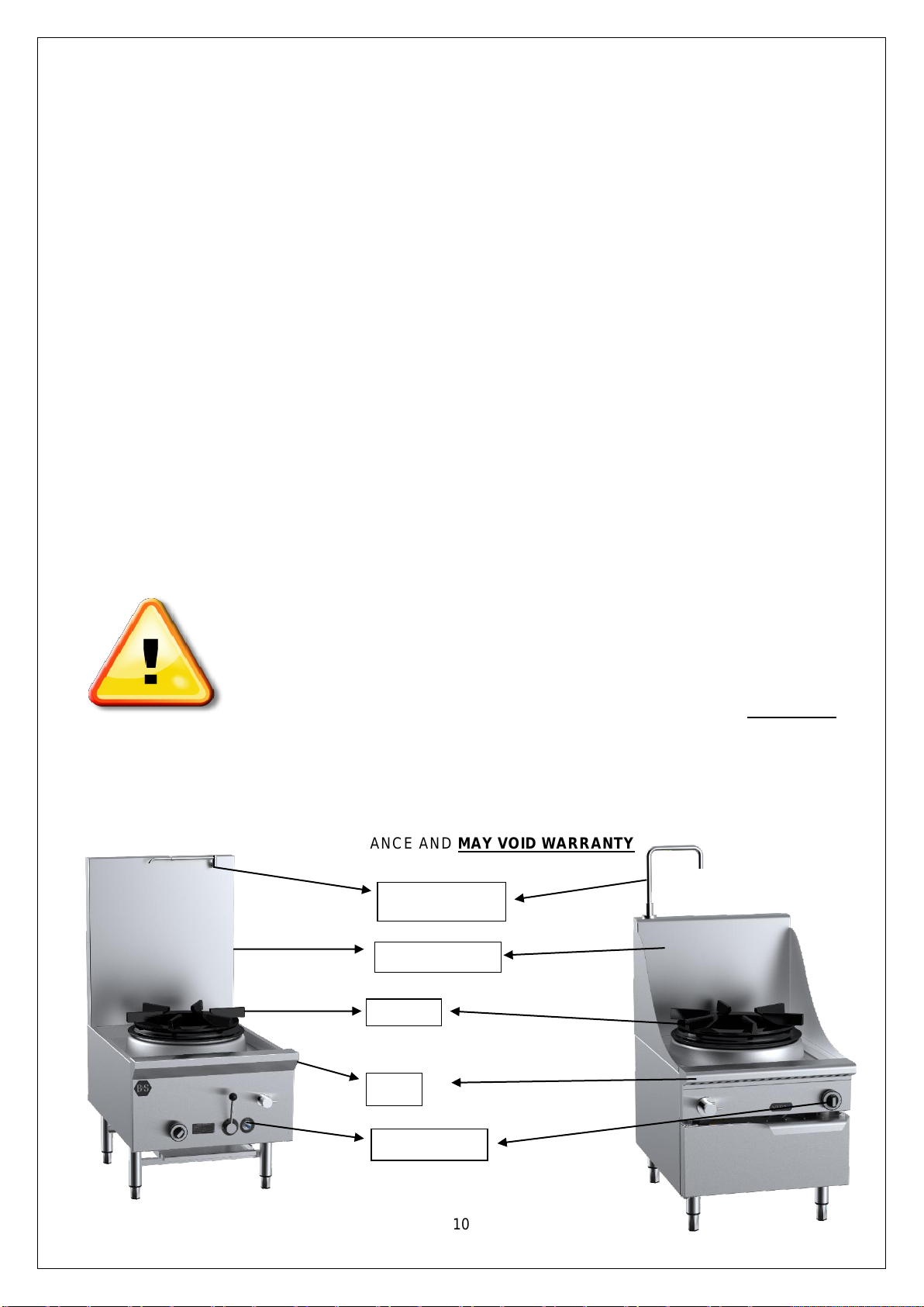
FAILURE TO FOLLOW THE INFORMATION PROVIDED IN THIS BOOKLET WILL VOID THE B&S
WARRANTY AND MAY RESULT IN DAMAGE TO EQUIPMENT OR INJURY TO PERSONNEL.
Please note that checking and adjusting of burner pressures on commercial catering appliances is an
obligation of gasfitters.
The relevant legislation is as follows from the Plumbing Regulations 2008 administered by the Victorian
Building Authority:
Gas fitting work defined
(1) Gas fitting work is the construction, installation, replacement, repair, alteration, maintenance, testing
or commissioning of any pipe, appliance, flue, fitting, apparatus, control or other item that is
involved with the supply or use of gas and that is fitted downstream of the outlet of a customer billing
meter or a consumer's gas storage container
As per AS/NZS5601.1, clause 6.11.1, this gas appliance must be commissioned by a suitably authorized
person who;
(a) Installed the appliance when gas is available at the time of installation; or
(b) Makes gas available to the appliance if gas was not available at the time of installation
As per AS/NZS5601.1, clause 6.11.3, the commissioning of this appliance shall take full account of special
design features, the manufacturer’s instructions and the appliance safety requirements.
As per AS/NZS5601.1, clause 6.11.4, the commission of this appliance shall include all of the following;
(a) Testing and purging of the appliance and installation as appropriate.
(b) Checks to ensure the appliance is in safe working order.
(c) Ignition of each burner of the appliance and where necessary adjustment, in accordance with the
manufacturer’s instructions.
(d) Testing of flue performance.
(e) Testing of all safety devices for correct operation.
(f) Instruction of the consumer, where available, on the safe and correct operation of the appliance
and any auxiliary equipment.
(g) Handing of the appliance operating instructions to the consumer, or if the consumer is not present,
leaving the instructions in a suitable location on the premises.
Installation Instructions
Regulations
The appliance must be installed only by authorised persons and in accordance with the manufacturer’s
installation instructions, local gas fitting regulations, municipal building codes, AS 5601 –Gas Installations
and any other health and safety regulations, local authority, gas, electrical any other statutory regulations.
Data Label
The data label is located on the front of the appliance. This appliance is suitable for Natural Gas and LPG.
Please ensure that the gas supply matches the Data Label ensuring that the gas supply is correct for the
appliance being installed and that adequate supply pressure and volume is available –refer to appliance
data plate for MJ/h consumption, injector sizes of main burners/pilots, etc.

8
Ventilation
This appliance should always be installed under an extraction hood. Ventilation must be in accordance with
AS5601 - Gas Installations. In general, the appliance should have adequate ventilation for complete
combustion of gas, proper ventilation and to maintain temperature of immediate surroundings within safe
limits. It is compulsory that this appliance is installed under an extraction hood.
The appliance shall be installed with an exhaust system comprising a hood and duct system. The hood shall
be made of a material which is impervious to fat, grease and vapour. It shall be constructed so it can be
readily and efficiently cleaned. Its inside faces shall be smooth and free of obstructions and all joints shall be
grease tight.
The hood shall be located so as to effectively ventilate the steamer and shall extend at least 150 mm beyond
the perimeter of the stock pot. The exhaust duct system shall be adequately sized and shall not get
connected to any other ventilating or exhaust system.
As suitable grease trap shall be provided to prevent grease vapour entering the exhaust system and shall be
located to avoid constituting a fire hazard and be readily accessible for regular cleaning.
Unless adequately protected a hood and a duct shall be fitted at least 450 mm from any combustible material
and so that the lower edge of the grease filter is no less than 1.35 meters above the cooking surface.
(please refer to AS/NZS 5601 clause 6.10.2.2 to verify clearances for ventilation.)
B&S units can be installed in a domestic environment provided the installation is strictly in
accordance with the manufacturer’s instructions and as per the AS/NZS5601.1 (please refer to the
latest version when released). The installation of the unit must comply with clauses 6.2.4, 6.10.2 and
6.10.1.15 and an exhaust system shall be installed according to AS1668.1 and AS1668.2 interlocked
to the gas supply. B&S shall not be responsible for any unauthorized and/or non-compliant
installations and will void the warranty.
Combustible Surfaces
Clearances to combustible surfaces must be in accordance with AS/NZS 5601.1 - Gas Installations, clause
5.12.4.5. Install on a flat/level floor. Where the floor is not fire resistant, a fire resistant material shall be put
under the appliance which shall have a fire resistance rating at least equal to that of 10mm millboard. The
material shall extend at least 50mm beyond the edge of the appliance.
Leave a clearance of at least 200mm between the appliance and any combustible surface.
Please refer to table 6.9 and 6.10 in AS 5601.1. clause 6.10.2.2 and 6.10.2.3. Table 6.10 (2013 version)
is given below. (Please refer to the latest version when released)
MINIMUM CLEARANCE AROUND COOKING SURFACE AREA
The clearance to combustible surfaces from commercial catering equipment shall be as specified in the
appliance manufacturer’s instructions and shall not be less than the clearance specified in the table below.
Cooking surface area
Minimum clearance in mm
A
Above the cooking surface of a gas appliance
600
B
Subject to C from a cooking surface area having an open
flame cooking appliance and no means of preventing
cooking vessels from overhanging the edge of the gas
appliance
250
C
From the side of a cooking appliance where the
combustible surface is at least 100mm below a cooking
surface area
50
D
From a gas appliance flue way or rear of the gas appliance
with a splashback
50
E
From the rear or side of a gas appliance which is not an
open flame gas cooking appliance
50

9
Notes:
1. The cooking surface area is defined as being that part of the gas appliance where cooking normally
takes place and does not include those parts of the gas appliance containing control knobs.
2. These clearances do not apply where an adjacent surface is of a non-combustible material or is
combustible but protected with a fire-resistant material. The fire-resistant material may be covered by
ceramic tiles or stainless steel to meet appropriate requirements relating to health protection.
3. Care should be taken where a combustible surface is covered by a non-combustible material for
example, covering a combustible surface with stainless steel will not prevent heat transfer, and in
some circumstances hazardous situation could arise.
Gas Connection
The gas connection is male 3/4”BSP and is situated at the rear of the appliance below the main body
frame. The number of gas inlets corresponds to the number of stock pot support rings the appliance is
fitted with. The inlet is to the ¾”elbow located at the rear of the appliance.
This appliance is available in models for fixed installation or in models fitted with lockable wheels/castors.
The appliance must be connected with rigid pipe as specified in AS5601. For fixed installation models
connect with 20mm copper tube and an AGA approved isolating ball valve. For models fitted with lockable
wheels/castors an Australian certified stainless steel braided flexible hose of adequate internal diameter
must be used. The fitting of the hose must comply with the relevant sections of gas installation code
AS/NZS 5601. A restraining chain or wire must be fitted. We recommend a maximum length of 1.5 m for
the flexible hose. When the appliance is in position all of the wheels/castors must have the built in lock on
to prevent any movement of the appliance. An Australian certified isolating ball valve must also be fitted.
BEFORE CONNECTING NEW PIPE TO THIS APPLIANCE, THE PIPE MUST BE BLOWN OUT
THOROUGHLY TO REMOVE ALL FOREIGN MATERIAL. FOREIGN MATERIAL IN THE BURNER AND
GAS CONTROLS WILL CAUSE IMPROPER AND DANGEROUS OPERATION.
Connect to gas.
Pressure Test Point
All appliances that are dispatched from our factory are tested and adjusted according to the specifications for
the required gas type. The regulator may require adjustment to achieve required gas pressure.
Check the burner pressure at the test point on the regulator. The test point pressure should be adjusted to
1.00 kPa –Natural gas or 2.60 kPa –LPG with the burners operating at maximum.
Water Connection
The water connection is 15mm copper and is situated at the rear of the appliance below the main
body frame. The number of water inlets varies to client’s particular needs. Water isolation valves are fitted
to all water inlets. Ensure water is flushed through before final connection.
For all appliances installed with lockable wheels or castors, flexible hoses( according to Australian
standards) should be used for water connection.
Water waste outlet is located on the left hand side of the waste gutter of the appliance (50mm connection).
The water inlets and water drains should be connected with rigid copper pipes. Plastic/PVC piping
should not be used for connection of waste outlet which will void warranty if done so.
Before Leaving - Commissioning
Check all connections for gas leaks with soap and water. Do not use a naked flame for detecting leaks.
Ignite the pilot and main burners as prescribed below to ensure correct operation of gas valves, burners and
ignition. When satisfied with the operation of the appliance, please instruct the user on the correct method of
operation. Ensure that this instruction manual is left with owner of the appliance.
Chimney burner
A. Light the appliance by pressing in the flame safe guard (blue) button and while holding it in turn the

10
pilot burner knob anti-clockwise to “ON”.
B. Light pilot manually.
C. Continue to hold in the flame safe guard button for about 25 to 30 seconds.
D. Observe whether the pilot is alight.
E. If not repeat steps A. to D.
F. If it is alight turn main burner valve anti-clockwise to the “ON”positions
G. Check that burner is properly alight.
Chimney Burners –Pilot Light Chimney Burner
A. Ensure pilot light head is located no further than 45mm from the injector located opposite the
burner inlet.
In the event the appliance fails to operate correctly, check the following;
1. Data plate to ensure correct gas type and pressure (adjust if necessary)
2. Adjust aeration by adjusting air shutter located at the front of the venture of the main burner.
3. Injector sizes –check against data plate and installation manual
4. View pilot size and adjust if required.
In case appliance fails to operate correctly after all checks have been carried out, please contact;
B&S Commercial Kitchens Pty Ltd
57 Plateau Road
Reservoir VIC 3073
Tel.: + 61 3 9469 4754 Fax.: + 61 3 9469 4504 E-mail: info@bscommercialkitchens.com
Operating Instructions
WARNING
•DO NOT spray aerosols in the vicinity of this appliance while it is in operation.
•DO NOT store or use flammable liquids or items in the vicinity of this appliance.
•Prior to lighting, smell area surrounding the appliance for gas (please note that as
some gas types are heavier than air, we recommended the operator to also smell
the floor around the appliance).
•In the event you smell gas: DO NOT light any appliance. DO NOT touch/ operate
any electrical switch or phone in your building. Call local gas supplier immediately
and follow their instructions.
IMPORTANT WARNING!
ENSURE NO OR MINIMAL AMOUNTS OF OIL AND FOODSTUFFS FALL INTO THE BURNER AREA
WHILST COOKING. FAILURE TO DO SO MAY AFFECT THE EFFICIENT AND SAFE OPERATION ON
THE APPLIANCE AND MAY VOID WARRANTY
Laundry arm
Splashback
Trivet
Hob
Gas controls

11
Lighting Instructions
1. Turn main gas valve to ‘OFF’.
2. Turn pilot valve anti-clockwise to ‘ON’ position.
3. Depress blue button on flame failure control and manually ignite light pilot.
4. When pilot is alight, keep holding down the blue flame failure button for approximately 15
seconds.
5. Observe the pilot flame is established. If pilot flame goes out wait five minutes and repeat
steps 1 to 4.
6. Turn main gas valve to ‘HIGH’ position.
Shutdown Procedure
1. Turn main gas valve to ‘OFF’.
2. Turn pilot control valve clockwise to turn off.
3. Observe pilot flame is extinguished.
Telescopic Laundry Arm –Manual Control (Water Cooled Models)
The telescopic laundry arm serves the purpose for cleaning the appliance and for filling the stock pot
cooking vessel with water to be used for cooking purposes. To activate;
1. Locate spindle on front panel with ‘Spout’ sticker located above it.
2. Turn spindle anti-clockwise to activate water from laundry arm.
3. To cease water flowing from laundry arm, turn ‘Spout’ spindle clockwise.
IMPORTANT WARNING!
NEVER LEAVE WATER RUNNING FROM TELESCOPIC LAUNDRY ARM WHILST POSITIONED
OVER THE STOCK POT SUPPORT RING WITH NO POT/PAN POSITIONED ON IT. ALWAYS MOVE
TELESCOPIC LAUNDRY ARM PARALLEL TO THE SPLASHBACK WHEN THE APPLIANCE NOT IN
USE. DIRECT FLAME CONTACT WITH LAUNDRY ARM MAY DAMAGE OPERATION OF LAUNDRY
ARM SPOUT.
Telescopic Laundry Arm Operation with Knee Valve –Where Fitted
The Laundry arm also serves the purpose of cleaning the appliance and/or for filling a stock pot vessel with
water to be used for cooking purposes.
Flow cycle is actuated by deflection and release of the flow lever in any direction from the rest position. The
adjustable flow rate automatically turns off with a non-concussive action after approximately 15 seconds.
Closing time is not adjustable.
IMPORTANT WARNING!
IN THE EVENT OF FAILURE OF THE WOKSPOUT, WATER FLOW CAN BE CONTROLLED MANUALLY
BY USING THE SPINDLE LOCATED ON FRONT PANEL (WHERE FITTED). WHERE NO SPINDLE
FITTED, WATER SHOULD BE SWITCHED OFF FROM THE ISOLATION VALVE (WHICH IS
RECOMMENDED TO BE FITTED WHEN INSTALLED) AND CONTACT AUTHORISED/ LICENSED
SERVICE PERSONNEL.
Maintenance and Care
To ensure longevity and continued performance efficiency of you appliance, a good cleaning and
maintenance program is paramount. In general the use of steel wool abrasive cloths/cleaners/powders
should not be used to clean this appliance.
Daily Checks & Service
•Look for any foreign materials in burner area, leaks, damaged knobs and any other signs that the
stock pot table is not ready and safe for operation. Inspect burner area and ensure pilots are in
position near the burner, and that the pilot flame when ignited is blue in color and approximately 20-
40mm in length. If fitted with thermocouple ensure pilot flame is in contact with it. Call the
manufacturer if you see any problems. Always ensure that area surrounding pilot and thermocouple
is clear of any fats, oils or foodstuffs.

12
•Clean the exterior surfaces of the stock pot with a clean, damp cloth soaked with mild detergent to
remove any food stuffs, oils, dust and any other materials.
•Ensure the primary water drain (located in gutter) is cleared of any food stuffs during operation of
the appliance and on completion of use of the appliance.
•The spillage trays located under the main body of the appliance should be removed (by pulling out)
and any carbonized foodstuffs and oils should be removed using a clean, damp cloth soaked in a
mild detergent.
Yearly Checks & Service
•The appliance should be inspected and adjusted periodically by a qualified service person as
part of any kitchen maintenance program.
•B&S recommends that this appliance is inspected at least annually by an authorized service
technician as follows:
oInspect the table inside-out for excessive build-up of any fats, oils and foodstuffs.
oInspect that the burners and other components (i.e. pilots, thermocouples, etc.) are in good
condition and functioning properly.
oInspect all gas connections for leaks and ensure all connections are tightened properly.
oEnsure burner manifold pressure is in accordance with that specified on the data plate of the
appliance.
oInspect all gas connections for leaks and ensure all connections are tightened properly.
In case of difficulties, contact B&S Commercial Kitchens Pty Ltd or their authorized service agent.
Servicing Instructions
WARNING!
•Servicing shall be carried out by authorized personnel only. Failure to do so will void
the B&S warranty and may result in damage to equipment or injury to personnel.
•Before commencing any disassembly/ assembly of gas controls, please ensure the
gas supply is turned off (isolated).
FAILURE TO DO SO WILL VOID B&S WARRANTY AND MAY RESULT IN DAMAGE TO EQUIPMENT
OR INJURY TO PERSONNEL.
Abnormal Operation
Any of the following are considered to be abnormal operation and may require servicing;
•Incomplete ignition of burner/burner failing to keep alight.
oCheck burner is not blocked.
•Yellow tipping of the burner flame.
oCheck aeration of burner.
•Gas valves which are difficult to turn.
•Burner failing to keep alight.
Gaining Access to Gas and/or Water System
To gain access to gas system/components;
1. Undo nut (by turning anti-clockwise) located on the front of the flame failure valve (blue button).
2. Remove knob off pilot valve by gently pulling forward.
3. Remove nut located centrally on the main gas valve (red handle).
4. Remove knee valve wand by unscrewing from main body of knee valve (where fitted).
5. Where deck cooling is fitted remove water spindle control by;
a. Unscrewing cold button on spindle.
b. Gently remove dome handle by gently pulling forward.
c. Unscrew flange by turning anti-clockwise.
d. Unscrew water spindle by turning anti-clockwise (ensure spindle washer is removed).
6. Remove screws located on bottom corners of front panel. Ensure any screws located on the inside
of the gutter panel are also removed.

13
7. Gently pull front panel outwards from the bottom and lift front panel upwards.
8. REASSEMBLE IN REVERSE ORDER.
Removal of Burner for Service
Follow procedure described under GAINING ACCESS TO GAS AND/OR WATER SYSTEM;
1. Undo barrel union located at in the centre of the gas manifold.
2. Remove burner support screw by undoing wing-nut located on the bottom front of the appliance
frame.
3. Gently lift burner upwards slightly and pull burner outwards.
4. REASSEMBLE IN REVERSE ORDER.
Pilot and Flame Safeguard
Access to pilot assembly is gained by removing the wing-nut located to the left of the pilot assembly which
secures it to the burner support bar, and gently pull forward to gain greater access (refer picture).
1. To service/remove the thermocouple;
a. Undo the nut located underneath and above the thermocouple at the pilot assembly and
gently pull thermocouple downwards.
b. Remove thermocouple from flame failure valve by unscrewing.
c. Reassemble in reverse order.
2. To service/remove pilot burner;
a. Undo nut located underneath the pilot burner on the pilot assembly.
b. Gently pull down pilot flexible gas tube.
c. Remove injector from pilot and clean (if required).
d. Reassemble in reverse order.
3. REASSEMBLE IN REVERSE ORDER.
Adjustments
Pilot
1. Remove front panel as described under GAINING ACCESS TO GAS CONTROL.
2. To increase gas pressure to pilot, turn adjustment screw located at the top right hand side of the
flame failure devise anti-clockwise.
3. To decrease gas pressure to pilot, turn adjustment screw located at the top right hand side of the
flame failure devise clockwise.
4. REASSEMBLE IN REVERSE ORDER ENSURING POSITION OF PILOT IS AS FOLLOWS;
Ensure pilot light head is light head is located no further than 45mm from the injector located
opposite the burner inlet.
Servicing Wok Spout –Where Fitted
The Wok Spout has a few wearing parts and these comprise a single flow control O-ring in the tap body and
two sealing O-rings on the swivel spout. Whilst it is expected that servicing would only be required at
approximately 200,000 cycles, it recommended that a preventative service be carried out every two years.
Please contact manufacturer for service kit.
Servicing Knee Valve –Where Fitted
The knee valve incorporates a cartridge design for ease of service.
1. Follow procedure described under GAINING ACCESS TO GAS AND/OR WATER SYSTEM
2. To gain access to knee valve cartridge undo knee valve where the deflector meets the cartridge
area.
3. REASSAMBLE IN REVERSE ORDER.
Gas Type Conversion
The following parts componentry require changing the appliance from NG to LPG (vice-versa);
1. Regulator.
2. Burner.
3. Pilot.
In case of any failure in the functioning of the knee valve, unscrew the head assembly and clean the

14
mechanism under running water. Only use liquid cleaning products. All cleaning products containing
dry powder or powder in suspension are not to be used!
A specific devise is integrated in the cartridge unit to adjust the flow rate. To adjust the flow rate;
1. Undo head assembly
2. Pull off flow adjustor
3. On the exposed end of the housing there are 4 cut-outs for alternative flow rates.
4. Select one for increased/reduced flow.
5. Replace flow adjustor with window over selected cut-out.
6. Screw head assembly into the tap body and tighten fully.
Table 5: Troubleshooting
FAULT
POSSIBLE CAUSE
CHECKS
Pilot light not igniting
Blockage of pilot
Adjustment of pressure from flame
control
Check pilot injector is not blocked
as described in servicing
instructions - pilot and flame
safeguard
Check gas pressure to pilot as
described under servicing
instruction - adjustments
Pilot light not establishing
Positioning of thermocouple
Faulty thermocouple
Faulty flame failure control valve
Check connection of the
thermocouple to the control is not
loose
Adjust positioning of thermocouple
to ensure pilot flame is hitting
thermocouple
Contact manufacturer or
authorized service agent
Contact manufacturer or
authorized service agent
Pilot established, main burner not
lighting
Faulty thermocouple
Faulty flame failure control valve
Contact manufacturer
Telescopic laundry arm constantly
running (on water/deck cooled
stock pot table)
Warn tap washer
Change washers in tap assembly
Contact manufacturer or
authorized service agent
Wokspout constantly running
water when in 'OFF' position
Faulty 'O' ring in Wok spout
Changing of 'O' ring as per service
kit and instructions provided with
appliance
Contact manufacturer or
authorized service agent
Short/long laundry arm constantly
running (when fitted with timer
operated knee valve)
Faulty knee valve
Faulty knee valve cartridge
Changing of knee valve cartridge
Contact manufacturer or
authorized service agent
To obtain further service information concerning this appliance, please contact;
B&S Commercial KitchensPty Ltd
57 Plateau Road
Reservoir VIC 3073
Tel.: + 61 3 9469 4754 Fax.: + 61 3 9469 4504 E-mail: info@bscommercialkitchens.com

15
STANDARD WARRANTY CONDITIONS
B&S Commercial Kitchens Pty Ltd of 57 Plateau Road, Reservoir, Victoria (hereinafter called ‘B&S’)
undertakes by this warranty, that B&S or its agent will pay for the cost of labour and parts which B&S or its
agent find defective for:
K+ Range - eighteen (18) months from date of installation/hand over for projects.
B+S Black Range –twenty four (24) months from date of installation/hand over for projects.
Verro Range –thirty six (36) months from date of installation/hand over for projects.
The liability of B&S under this warranty is limited to the repair or replacement of defective goods or
components. All other costs including, without limitation, cartage, carriage and installation shall be borne by
the purchaser.
IMPORTANT
Prior to requesting a service call, please be sure that cooking equipment is being used and maintained in
accordance with the instruction manual provided with your cooking equipment. Please also be sure that your
cooking equipment has been installed in accordance with the manual by a qualified installer. All cooking
equipment must be commissioned by installer upon completion of installation. Failure of these procedures
will result in non-warranty service costs.
Warranty labour is supplied free of charge during business hours (8 a.m. to 4 p.m. AEDST) Monday
to Friday. Should warranty work be requested outside of our normal working hours, a labour charge
will be applied equivalent to a normal hour rate, with out of hours penalty rates. Penalty rates amount
must be borne by the purchaser. Claims for non-covered parts, no faults found, travel over 100km or
other items outside our standard terms and conditions will be chargeable. Note: Any extra time spent
on site due to required inductions etc. is not covered by warranty.
1. This warranty applies only for mainland Australia and Tasmania, and does not cover any service
consequent upon accident, alterations, misuse, fire, flood or act of God. Warranty for New Zealand is
twelve (12) months parts and labour for K+, B+S Black & Verro Ranges.
2. This warranty is valid only if the appliance has been installed in accordance with local regulations by a
duly authorised person, and the B&S installation instructions provided with the appliance. If in doubt,
please contact B&S or their representative for further information. No responsibility will be accepted for
defects or damages by improper installation, for changes to the product not authorised by B&S or for the
operation outside the technical specifications of the appliance.
3. This warranty is conditional upon the appliance being used in normal commercial catering operations.
4. This warranty is the only express warranty given by the Company. No person has authority to change or
to add to these obligations and liabilities.
5. The Company has the right to determine whether or not a fault is caused by faulty workmanship or
material or that any part is defective.
6. This warranty does not apply to any loss suffered through or resulting from the non-operation or the
ineffective operation of the cooking appliance or any part of the cooking appliance.
7. This warranty does not extend to goods and components thereof manufactured either entirely or
substantially of glass or similar substances, light globes, infrared or quartz tubes and electrical controls
or elements.
8. While the goods are in custody of the seller for investigation or repair, they shall be at the risk of the
purchaser and no liability shall attach to the Company, its servants or agents for any damage occasioned
to, or loan of, the goods whatsoever.
9. All warranties are non-transferable and are only applicable to the original end user (purchaser).
10. All warranty work must be carried out by a B+S approved service technician.
The Purchaser must give notice to the Company immediately upon it becoming aware of the alleged
defect and in any event before the expiration of the appropriate warranty period.
B+S will endeavour to have a service technician on site for all warranty service requests within a 24
hour period or by end of next business day at the latest. All warranty requests must be in writing by
either lodging a warranty request through B+S website or be emailing
clientservices@bscommercialkitchens.com. Details of installer such as contact name, business name,
telephone number and license number must be provided to avoid any delays.

16
11. Nothing in this warranty, however, shall be construed as affecting any rights you may have under the
Trades Practices Act or any other Commonwealth or State Legislation which gives you rights which
cannot be modified or excluded by agreement.
12. SPECIAL PROVISIONS –NOT COVERED BY WARRANTY
•Cleaning of spark and ignition sensors is not covered by warranty. Damage caused by oils, water and
foodstuffs falling into burners or pilots will not be covered under warranty.
•Cleaning of burners due to blockage of burner orifices caused by foodstuffs and/or oils is not covered by
warranty.
•Breakage of pilot knobs, knee valve handles and knee wands are not covered under warranty.
•Thermocouples, piezo leads and ignitors are only covered by twelve (12) months parts and labour
across K+, B+S Black and Verro ranges.
•Seizure of gas cocks and knobs.
•Cleaning of blocked drains.
•Damage caused by lime scale and/or corrosion.
•Parts not supplied by B+S or a B+S authorised service technician.
•Damage caused by rodents and insects.
•Scheduled general maintenance.
•Normal wear and tear of parts
•Filters for DSK Deck Steamers
Additional costs are payable for:
Accommodation, cost of transport such as flights/ferries, poor access and waiting times.
B+S Commercial Kitchens
57 Plateau Road, Reservoir Victoria 3073 Australia
+61 3 9469 4754 | info@bscommercialkitchens.com | bscommercialkitchens.com
This manual suits for next models
6
Table of contents
Other B+S Commercial Food Equipment manuals
Popular Commercial Food Equipment manuals by other brands

Flavor Burst
Flavor Burst CTP 80FCB Equipment, Maintenance and Operations Manual

Electrolux
Electrolux PR700 Installation, operation and maintenance

Skyfood
Skyfood CLM-300 instruction manual

Bartscher
Bartscher 200240 manual

Winston Industries
Winston Industries HA4002 Use & care manual

Electrolux Professional
Electrolux Professional T10E manual