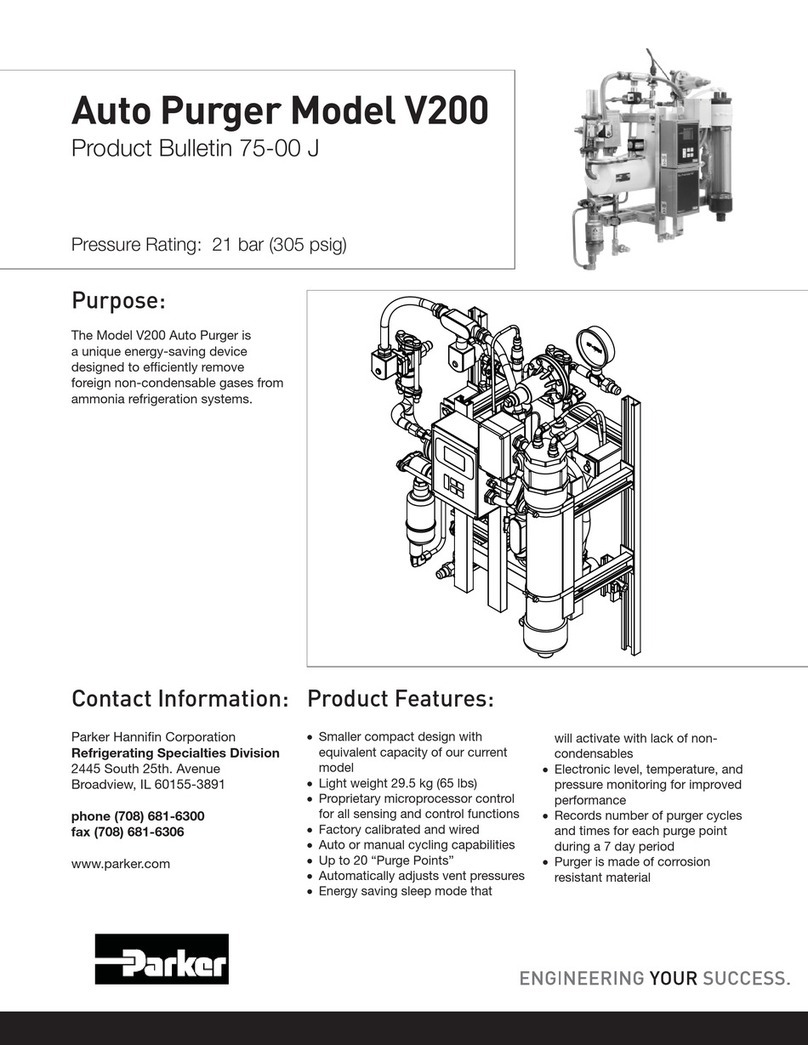
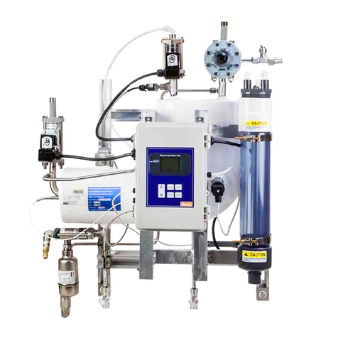
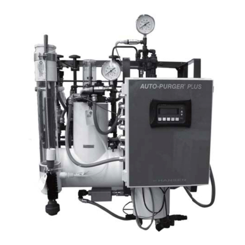
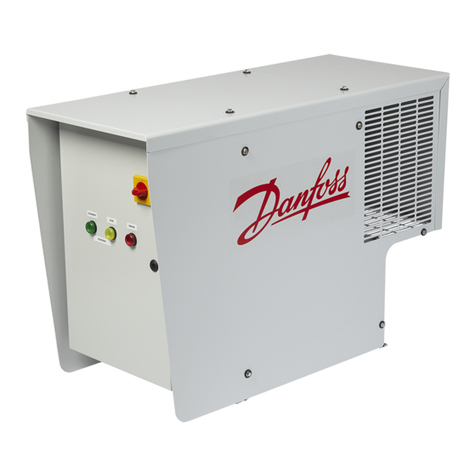
BPS YZ102 User manual

CLASS I APPLICATIONS
15 CUBIC FEET Model YZ102
Type Y or Z
Purge Unit
Installation & Operation Manual
BPS YZ102 IOM-R1.0 9/18
Copyright © 2018 - Best Purging Systems Corporation All Rights Reserved
Model YZ102-CI-W or B-V
With Pressure Switch
shown w/ Mounting Flange
Model YZ102-CI-W or B-H
With Pressure Switch
shown w/ Mounting Flange
Model YZ102-CI-L-U
Less Pressure Switch
shown w/ Mounting Flange

© 2018 - Best Purging Systems Corporation
Page 2 of 14 BPS YZ102 IOM-R1.0
Introduction
To assist you through the installation and operation of your enclosure pressurization unit, Best Purging Systems has provided the
following information boxes throughout this manual. This information is intended to clarify certain differences between the model styles
and congurations of this unit and to warn the user and installer of potential dangers due to improper installation or operation.
Important Manual Information Designators
IMPORTANT NOTE WARNINGHELPFUL HINT
Technical Description
Model YZ102 is a Type Y or Z purge unit designed to protect
electrical equipment in Class I hazardous locations. Type Z
applications reduce the hazardous location rating inside the
enclosure from Division 2/ Zone 2 to non hazardous. This
allows general purpose equipment to operate in Division 2/
Zone 2 areas. Type Y applications reduce the hazardous
location rating inside the enclosure from Division 1/ Zone 1 to
Division 2/ Zone 2. This allows Division 2/ Zone 2 equipment
to operate in Division 1/ Zone 1 areas.
Model PV-2 spark arresting Purge Vent MUST be installed
on the protected enclosure.
This unit is designed to meet or exceed NEC - NFPA 70, NFPA
496, EN 50016 and IEC 60079-02 requirements.
Operating this unit without a Model PV-2 Purge
Vent may cause harm, death or dismemberment to
personnel and can cause damage to instrumentation.
This unit is NOT intended for dilution applications.
Please consult factory for more information.
A copy of this manual must be read and retained by the
operator of this unit. User’s agent’s are responsible for
transferring this manual to the user prior to installation and
start up.
This unit must be installed and operated per this manual.
The Authority Having Jurisdiction should be advised
before installation of this unit. This manual DOES NOT
supersede any national, local or plant codes.
All specications are subject to change without notice.
IMPORTANT NOTE
Page 2 Introduction
Technical Description
Important Notes
Important Manual Information Designators
Page 3 Identifying Your Unit
Model Number Designations
General Information
Unit Specications
Material Specications
Protected Enclosure Criteria
Major Components List
Page 4 Getting Starting
Pressurization Unit & Enclosure Connection
Requirements
Single Enclosure Connections
Multiple Enclosure Connections
Page 5 Unit Layout
Unit Layout & Component Description
Typical Pneumatic Flow Diagram
Page 6 Mounting & Installation
Universal, Vertical & Horizontal Mount Purge
Unit & Purge Vent Dimensions
Page 7 Mounting Set Up
Unit Mounting Instructions
Unit Tubing Instructions
Enclosure Warning Label(s)
Page 8 Pressurization Unit & Switch Set Up
Pressurization Unit Set Up
Pressure Switch Set Up
Typical Pressure Switch Wiring Diagram
Page 9 Pressurization Unit Operation
Cross Ventilation Diagram
Page 10 Warranty & Liability Statements
Page 11 Factory Repair & Service Guide
Page 12 Reference Information
Page 13 Maintenance & Service Notes
Page 14 Unit Identication Information
Table of Contents

BPS YZ102 IOM-R1.0 Page 3 of 14
© 2018 - Best Purging Systems Corporation
Unit Specications
Purge Time: 4 Volumes @ 1 minute per 1.0 cf
5 Volumes @ 1 minute per 0.8 cf
Protective Gas Supply: Air or Inert Gas
Gas Supply Pressure: 80 - 125 psi max.
Unit Supply Connection: 1/4” tube tting
Enclosure Supply: 1/4” tube tting
Enclosure Reference: 1/4” tube tting
Safe Enclosure Pressure: 0.25” w.c. / 6.22 Kb
Safe Press. Flow Rate: * 0.1 - 3.5 scfh per cf
Purge Enclosure Pressure: * 5” - 8” w.c.
Purge Press. Flow Rate: 4 scfm @ 60 psi.
* Enclosure Integrity determines actual Pressure & Flow
Material Specications
Unit Mounting Plate: 316 Stainless Steel Brushed
Regulator body: Enamel Finished Zinc
Filter & Handle: Polycarbonate
Enclosure Press. Gauge: Enameled Aluminum
Injection Press. Gauge: Polycarbonate/Brass
Tubing: 316 Stainless Steel
Tube Fittings: 316 Stainless Steel
Valves: 316 Stainless Steel
Valve Handles: Polycarbonate
Start up Labels: Silkscreened Lexan
Enclosure Warning Label: Stainless Steel
Protected Enclosure Criteria
The consumption of protective gas is directly related to the
integrity of the protected enclosure plus the type of purge
requirements, i.e. dilution and ventilation. The following
enclosure recommendations are provided to help minimize
protective gas consumption and increase purge unit efciency.
1. The enclosure should be fabricated to meet NEMA 4 or
12 / IP66 requirements.
2. Non metallic enclosures should meet ANSI/UL 94 V-O
or 94 5V.
3. Enclosure windows should be impact resistant and sized
as small as possible.
4. Enclosure surface temperatures must not exceed 80%
of the area’s auto-ignition temperature.
5. Avoid obstructions and barriers which could impede
protective gas ow through the protected enclosure.
Identifying Your Unit
Major Components List
Filter Regulator:
Enclosure Pressure Valve:
Purge Valve:
Purge Press. Indicator:
Enclosure Press. Indicator:
Optional Pressure Loss Alarm:
Enclosure Warning Label: EWL-1
General Information
All electrical connections of the protected enclosure and purge unit must be performed by trained and knowledgeable
personnel. In addition, all connections must be installed in accordance with the National Electrical Code (NEC) NFPA
70 and all relevant international, nation and local codes. The Authority Having Jurisdiction must approve all electrical
installations. Failure to follow electrical warnings can cause harm, death or dismemberment to personnel and can cause
damage to instrumentation.
WARNING
Model Number Designations
This enclosure pressurization unit is offered in various
styles. For proper installation and operation, examine
the Unit Model Number Nameplate to identify the Unit
Style, Area Classication and Type, as noted below.
Model # YZ-102-CI-L-U-¤
Div./Zone Reduction
Y- Div.1/Zone1 to Div. 2/Zone 2
Z- Div.2/Zone2 to Non-Hazardous
Unit Series
102- 1/4” Purge Unit
Area Classication
CI- Class I Areas
Pressure Switch Option
L- Provided Less Switch
W- Provided With CI, Gr. C&D EXP Switch
B- Provided With CI, Gr. B EXP Switch
Voltage*
120 VAC
24 VDC
OR
Optimal Conguration***
PM- Panel Mount
Mounting Options
U- Universal
Mounting**
V- Vertical
Mounting
H- Horizontal
Mounting
* For pressure switch option “B” only
** Not Available with pressure switch options
*** Panel Mount designed to mount through the wall of protected enclosure. U mounting only.
YZ103-CI-W-V
Purge Unit
Area Classification Reduction:
Type Z - Cl I, Div. 2/ Zone 2, Gr.
C&D, to Non-hazardous
Type Y - Cl I, Div. 1/ Zone 1, Gr.
C&D to Div. 2/ Zone 2, Gr. C&D
Purge Control for use in Hazardous
Locations. In accordance w ith the
National Fire Protection Association
Standard for Purged and
Pressurized Enclosures for Electrical
Equipment. NFPA 496 2003.
23HP

© 2018 - Best Purging Systems Corporation
Page 4 of 14 BPS YZ102 IOM-R1.0
Getting Started
Purge Unit & Enclosure Connection Requirements
1. No valves shall be installed between the Pressurization/
Purge Unit and the Protected Enclosure.
2. The Pressurization/Purge Unit should be located at eye
level.
3. The Pressurization/Purge Unit should be installed
adjacent to the protected enclosure.
4. Enclosure Supply and Purge Vent should be installed
at extreme opposite corners, to ensure adequate purge
ow through the Protected Enclosure.
5. Multiple Protected Enclosures must be purged in series
and should be connected from the smallest to the largest
enclosure.
6. Enclosure Supply connections between multiple
enclosures must be at least the diameter of the Purge
vent exhaust (3/4”).
1” Protective Gas
Supply Header
Purge
Unit
Unit Supply
1/4” Tubing
Protected
Enclosure
Purge Vent
Model # PV-2
Enclosure Supply
1/4” Tubing
Enclosure Reference
1/4” Tubing
Single Enclosure Connections
Multiple Enclosure Connections
Purge
Unit
Protected
Enclosure
#3
Protected
Enclosure
#2
Protected
Enclosure
#1
1” Protective
Gas Supply
Header
Unit Supply
1/4” Tubing
Enclosure Reference
1/4” Tubing
Enclosure Supply
1/4” Tubing
Multiple Enclosure Supply
3/4” Rigid Pipe
Purge Vent
Model # PV-2

BPS YZ102 IOM-R1.0 Page 5 of 14
© 2018 - Best Purging Systems Corporation
Unit Layout
Unit Layout & Component Description
Filtered Regulator
Purge Control Valve
Enclosure Pressure
Reference Connection
Unit Supply Connection
Enclosure Pressure Gauge
Enclosure Supply
Connection
Atmospheric Reference
Enclosure Pressure
Control Valve
Venturi Orice
Model YZ102-CI-L-U
Universal Mount
Less Pressure Switch
Rear View
Model YZ102-CI-W or B-V
Vertical Mount
With Pressure Switch
Rear View
Typical Pneumatic Flow Diagram
Denotes Customer
Supplied Tubing
Required
Purge Vent
Enclosure Pressure
Gauge
Optional EXP
Pressure Switch
Purge Injection
Pressure Gauge
Enclosure
Warning
Label
Protected
Enclosure
Enclosure
Supply
Enclosure
Reference
Inlet
Venturi
Orice
Protective
Gas Supply
Regulator Enclosure Pressure
Control Valve
Purge Control
Valve

© 2018 - Best Purging Systems Corporation
Page 6 of 14 BPS YZ102 IOM-R1.0
Mounting & Installation
Universal Vertical & Horizontal, Mount Purge Unit & Purge Vent Dimensions
Model YZ102-CI-W or B-H
Front View
Model PV-2-S
Side Mount Purge Vent
2.5”
4.5”
Model PV-2-T
Top Mount Purge Vent
2.5”
6.5”
Model YZ102-CI-W or B
Side View
C/L
4”
3.5”
Model YZ102-CI-W or B
Mounting Flange
YZ102-CI-L-U
Side View
C/L
4”
1.75”
12” Universal
Mounting Flange
Model YZ102-CI-W or B-V
Front View
Model YZ102-CI-L-U
Front View
12”
11.5”
11.5”
12”
0.25”
Typ. 8
0.5” 6”
6”
12”
11.5”
15.75”
0.5”
16.25”
8.125”
0.25”
Typ. 6
15.75”
8.125”
11”
11.5”
0.5”
16.25”
0.25”
Typ. 6
0.625”
12”
4.0”
3.375”
0.25”
Typ. 8
11.375”
10.3125”
1.6875”
0.625”
16.25”
4.0”
3.375”
0.25”
Typ. 4
15.5625”
14.9375”
1.3125”
0.6875”

BPS YZ102 IOM-R1.0 Page 7 of 14
© 2018 - Best Purging Systems Corporation
Unit Tubing Instructions
1. Carefully read “Protected Enclosure Criteria” on page 3
and “Enclosure Connection Requirements” on page 4
before proceeding.
2. The following instructions are for Units mounted external
to the Protected Enclosure. Consult factory for units
which are mounted inside or through the face of the
Protected Enclosure.
3. Connect 1” Protective Gas Supply Header to Unit Supply
Connection using 1/4” .035 welded or seamless wall
stainless steel, fully reamed tubing. Protective Gas
Supply tubing should not exceed 15 feet length and 5
bends.
4. Connect Unit Enclosure Supply Connection to the
Enclosure Supply bulkhead tting using 1/4” .035 welded
or seamless wall stainless steel, fully reamed tubing.
Enclosure Supply tubing should not exceed 5 feet in
length and 5 bends.
5. MULTIPLE ENCLOSURE CONNECTIONS ONLY.
Connect Multiple Enclosure Protective Gas Supply Piping
(3/4” rigid pipe, fully reamed) from Protected Enclosure
#1 to Protected Enclosure #2. Repeat procedure for
connection between Protected Enclosure #2 and #3.
Protective Gas Supply piping should not exceed 10 feet
length and 5 bends between each enclosure.
6. Connect Unit Enclosure Reference Connection to the
Enclosure Reference bulkhead tting using 1/4” .035
welded or seamless wall stainless steel, fully reamed
tubing. Enclosure Reference tubing should not exceed
20 feet length and 5 bends.
Unit Mounting Instructions
1. Carefully read “Protected Enclosure Criteria” on page 3
and “Enclosure Connection Requirements” on page 4
before proceeding.
2. Determine the Mounting conguration for the purge unit.
See “Typical Mounting Congurations.”
3. Firmly secure the unit mounting ange, if utilized, to the
unit face plate using the hardware provided.
4. Drill and ream four mounting holes in the protected
enclosure. (see page 6 for unit mounting flange
dimensions and unit layout)
5. Based on “Enclosure Connection Requirements” on page
4, drill and ream a 29/64” hole in protected enclosure,
install 1/4” Enclosure Supply Bulkhead tting. NOTE:
Protected Enclosure Supply should be installed at
extreme opposite corner from part # PV-2 Purge Vent
and 8” from the Enclosure Reference Connection.
6. Next, drill and ream a 29/64” hole in protected enclosure,
install 1/4” Enclosure Reference Bulkhead tting. NOTE:
Protected Enclosure Reference should be installed at
least 8” from the Enclosure Supply Connection.
7. Install PV-2 Purge Vent at extreme opposite corner from
the Enclosure Supply Connection. (WARNING: The PV-2
Purge Vent is gravity operated and MUST be mounted
in a true vertical position.)
8. Install the PV-2 Purge Vent Mounting Hub through a
1-1/4” hole on the Protected Enclosure.
9. Secure the Purge Vent from inside the Protected
Enclosure using the Purge Vent Mounting Nut.
10. Secure Purge Unit Mounting Flange to protected
enclosure using hardware provided.
Mounting Set Up
Enclosure Warning Label (EWL) MUST be permanently afxed on or near all protected enclosure doors, entries and openings.
Enclosure Warning Label(s)
Frame/Panel MountBottom MountTop MountLeft Mount Right Mount
Typical Mounting Congurations
WARNING NOTICE
THIS ENCLOSURE CONTAINS HOT COMPONENTS
ENCLOSURE SHALL NOT BE OPENED UNLESS AREA IS KNOWN TO BE FREE
OF FLAMMABLE MATERIALS OR UNLESS A LL DEVICES HAVE BEEN
DE-ENERGIZED FOR THE TIME SPECIFIED BELOW.
MINIMUM COOLONG TIME:
WARNING - PRESSURIZED ENCLOSURE
ENCLOSURE SHALL NOT BE OPENED UNLESS AREA IS KNOWN TO BE FREE
OF FLAMMABLE MATERIALS OR UNLESS A LL DEVICES HAVE BEEN
DE-ENERGIZED. P OWER SHALL NOT BE RESTORED A FTER ENCLOSURE
HAS BEEN O PENED UNTIL C OMBUSTIBLE DUSTS HAVE BEEN REMOVED
AND ENCLOSURE HAS BEEN PURGED AND PRESSURIZED IN ACCORDANCE
WITH THE UNIT START UP INSTRUCTIONS.
AREA CLASSIFICATION PRESSURIZATION TYPE TEMPERATURE CODE
BEST PURGING SYSTEMS CORPORATION WWW.PURGEIT.COM LA MARQUE, TEXAS USA

© 2018 - Best Purging Systems Corporation
Page 8 of 14 BPS YZ102 IOM-R1.0
Customer Supplied Alarm
C NO NC
Typical Pressure Switch Wiring Diagram
Purge Unit Set Up
1. Ensure Protected Enclosure Power is OFF, Enclosure
Pressure Control Valve and Purge Control Valve are
closed and Protective Gas Supply is ON.
2. Test the Purge Vent, Model PV-2, for proper operation.
Using the eraser end of a pencil or similar object, insert
test object from inside the enclosure to conrm vent
relief ball is operating properly. Note: For side mounted,
Model PV-2-S, remove plug from bottom of tee tting to
test vent relief ball operation.
3. Close and Seal Protected Enclosure.
4. Slowly turn Enclosure Pressure Control Valve CCW until
a “Safe” 0.25” w.c. reading is shown on the Enclosure
Pressure Indicator. Note: Should Enclosure Pressure
Control Valve require more than a quarter turn to obtain
a “safe” enclosure pressure, carefully check all enclosure
connections and doors for leakage. Seal as needed.
5. Ensure a Minimum 60 psi reading on the Purge Injection
Pressure Gauge, adjust regulator if required.
6. Open the Purge Control Valve fully. The Enclosure Pressure
Gauge will go off scale to the high side, this normal.
7. During Purge cycle, conrm minimum 60 psi reading
on Purge Injection Pressure Gauge, adjust regulator if
required.
8. Close Purge Control Valve fully. The Enclosure Pressure
Indicator should return to a “Safe” 0.25” w.c. reading.
9. Calculate total protected enclosure volume (when empty).
Determine Purge Time required (5 minutes minimum).
Required Exchange Time/Enclosure Volume
4 Volumes 1 minute per 1.0 cf
5 Volumes 1 minute per 0.8 cf
10. Mark purge time on Unit start up instruction name tag
using a permanent marker.
11. Set up is complete. Remove any test equipment and
proceed to Optional Enclosure Pressure Switch Set up
if required.
Pressure Switch Set Up
1. The following directions are for purge models with the
sufx -W or -B which are supplied with a ame proof
differential pressure switch (DPS).
The differential pressure switch is intended solely for loss
of safe pressure alarm and should not be used to control
power to the protected enclosure.
IMPORTANT NOTE
2. Connect alarm system wiring to the DPS via rigid
conduit and seal or other approved wiring method for
the classied location.
3. The DPS provides a Form C Dry NO, NC and C contact
Note: -B switches require 120V AC or 24V DC power
to operate.
4. The alarm system should be connected in a fail safe
conguration.
Pressurization Unit Set Up
Protected Enclosures
Cross Ventilation Diagram
Required
Purge Vent
Enclosure Reference Tubing
Purge
Unit
Unit Supply Tubing
Protective
Gas Supply
Header

BPS YZ102 IOM-R1.0 Page 9 of 14
© 2018 - Best Purging Systems Corporation
Purge Unit Operation
1. Ensure Protected Enclosure Power is OFF, Enclosure
Pressure Control Valve and Purge Control Valve are
closed, Protective Gas Supply is ON and alarm system
is activated (if utilized).
2. Test the Purge Vent, Model PV-2, for proper operation.
Using the eraser end of a pencil or similar object, insert
test object from inside the enclosure to conrm vent
relief ball is operating properly. Note: For side mounted,
Model PV-2-S, remove plug from bottom of tee tting to
test vent relief ball operation.
3. Close and Seal Protected Enclosure.
4. Slowly turn the Enclosure Pressure Control Valve CCW
until a “Safe” 0.25” reading is shown on the Enclosure
Pressure Indicator.
5. Open the Purge Control Valve fully. The Enclosure Pressure
Indicator will go off scale to the high side, this is normal.
6. Conrm a Min. 60 psi on Purge Injection Pressure Gauge.
7. Allow unit to purge protected enclosure for the required
time marked on the Unit Start Up Instructions (5 minutes
minimum).
Required Exchange Time/Enclosure Volume
4 Volumes 1 minute per 1.0 cf
5 Volumes 1 minute per 0.8 cf
8. Upon completion of the required purge time, close
the Purge Control Valve fully. The Enclosure Pressure
Indicator will return to a “Safe” 0.25” w.c. reading.
9. Conrm protected enclosure “Safe” pressure is stable.
Energize protected enclosure equipment.
10. Loss of “safe” pressure requires immediate attention.
Protected enclosure power should be deenergized if
“Safe” pressure cannot be restored within a reasonable
amount of time.
Purge Control Valve
Purge Injection
Pressure Gauge
Enclosure
Pressure
Gauge
Enclosure
Pressure
Control Valve
Unit Start Up
Instructions
Optional EXP
Pressure Switch
Model YZ102-CI-W or B-V
With Pressure Switch
Front View
Model YZ102-CI-L-U
Less Pressure Switch
Front View

© 2018 - Best Purging Systems Corporation
Page 10 of 14 BPS YZ102 IOM-R1.0
Limitations of Liability
Limited Warranty Terms
WHEREBY Best Purging Systems Corporation, hereafter referred to as “Manufacturer,” is the sole manufacturer of this Product, Manufacturer
herein states a portion of the limitations of liability incurred due to any sale or use of the Product.
Manufacturer accepts no liability for any affects or damages incurred by the installation or operation of the Product which is used on any
enclosures, cases, containers or combinations thereof which are not constructed in complete accordance with the National Electric Code
and all applicable sections of NFPA 496, or which are not specied as acceptable for use within the constraints of design requirements
and information that may be contained within this Installation, Operation & Maintenance Manual.
Manufacturer and/or its Agents, Representatives, or Sub-Contractors accept no liability for PERSONAL INJURY, DISMEMBERMENT
OR DEATH, or for any affects or damages incurred to any device, component, enclosure, equipment or area caused by use of Product,
unless Product is installed, operated and maintained in complete accordance with this Manual and all applicable National Electric Code
and NFPA 496 requirements and OSHA regulations.
These Limitations of Liability supersede any and all claims of liability responsibilities claimed by the User and/or its Agents or Subcontractors
against Manufacturer and/or its Agents, Representatives, or Sub-Contractors regardless of their Terms of Purchase, surrendered hereto,
and shall survive from the date of sale to the date of discontinued use of the Product. Questions concerning stated and unstated limitations
to liability may be referred to the Corporate Management Group of the Manufacturer at 4725 Lawndale, La Marque, Texas 77568, USA.
Warranty & Liability Statements
ADVISEMENTS: This Warranty Statement is an excerpt for reference only, and is therefore superseded by any variance of Warranty
Terms and Conditions supplied with the Quotation or Sales Order Documents provided for this particular Product. All parts and services
provided for this Product must be made with Best Purging Systems Corporation (hereafter referred to as BEST) furnished or authorized
service parts and by BEST Technicians or by a BEST authorized service provider. Reference Quotation and Sales Order Documents for
complete Terms and Conditions, including clauses regarding warranty extensions, safety certications, trade certications and insurance,
special safety equipment and tools, required working conditions, warranty registration requirements, eligibility, exclusions and legal terms.
WARRANTY CONDITIONS: Subject to all terms and conditions herein, BEST extends a limited warranty against manufacturing defects
and workmanship for all Product that is installed and operated by the Purchaser and/or Client in complete accordance with all instructions
in the BEST Installation, Operation and Maintenance Manual in the United States, Canada and Mexico.
WARRANTY TERM: The Base Limited Warranty period for Product is effective for Twelve (12 Months) from date of BEST Factory shipment.
Upon proper registration of the Product by the Purchaser or Client within no more than Ninety (90) Days after BEST Factory shipment, a
Registered Limited Warranty shall become effective and extend the warranty period to Twenty-Four (24) Months after date of shipment.
Regardless of registration, the Commencement Date for either warranty period shall be the date of BEST Factory shipment, or under prior
special written agreement at time of Product purchase, no greater than Ninety (90) Days after the BEST Factory shipment date.
WARRANTY EXTENSIONS: An extended warranty shall extend the effective warranty based on the terms and conditions as negotiated
at time of purchase. The purchase of site start-up services or site acceptance testing from BEST and/or their authorized service provider
under contract to BEST shall alter the warranty Commencement Date of the Basic, Registered or Extended Warranty period to begin on
the day after Client Acceptance of site start-up services or site acceptance testing.
TERM LIMITATION: The installation of Product replacement parts and/or the provision of any eld service or troubleshooting services
under this limited warranty shall not extend the effective warranty period. The warranty period for any supplemental installation of Product
replacement parts and/or the provision of any eld service or troubleshooting services under this limited warranty shall therefore be
applicable only during the warranty period remaining under the effective Product Warranty.
WARRANTY COVERAGE: The Base Limited Warranty covers all necessary parts and labor during the rst Twelve (12) Months or up
to Twenty-Four (24) Months after date of shipment if product is registered in accordance with this warranty. Under either warranty term,
the warranty shall be effective to resolve any validated defect in parts and/or workmanship and is provided exclusively for the Purchaser
during integration and the Client upon delivery to the site of installation and use. Warranty is transferable from Purchaser to Client and
shall be in full effect and force during any hold over, commissioning or factory acceptance testing of Product regardless of whether Product
is operational or at installation site, except according to terms stated below under Registration Requirements.
WARRANTY REPAIR SERVICES: BEST may request proof of Product purchase and/or installation in order to provide Product parts and
service under this limited warranty. As BEST’s only responsibility and Purchaser and Client’s only remedy under this limited warranty,
BEST will furnish all necessary labor and/or replacement parts in accordance with Warranty Coverage Terms above, whether provided
by BEST or an authorized service provider acting on BEST’s behalf, without charge for the labor and/or parts, to repair any Product that
fails due to a manufacturing defect under normal use and maintenance. If a replacement part is not available at time of warranty service,
BEST may, at its option and sole discretion, provide a suitable replacement product. If Client selects unit repair at the BEST factory, the
client shall be responsible for freight to BEST, and BEST shall be responsible for cost of standard non-expedited freight back to client,
whereas client shall pay the difference for expedited freight if requested.
NON-WARRANTY SERVICES: All non-warranted parts provided and/or non-warranted services incurred during a warranty serviced
event at the request of the Purchaser or Client shall be provided at Purchaser or Client’s sole cost and expense. BEST reserves the right
to require a Purchase Order from the Purchaser or Client prior to accommodating any non-warranty services, and will require binding
estimates for services from all BEST certied contractors where and when possible or required.
BPS YZ102 IOM-R1.0 Page 11 of 14
© 2018 - Best Purging Systems Corporation
Factory Repair & Service Guide
Required Information
• Purchase order number and date (may be determined by Best Purging Systems when Serial Number is provided)
• Unit Model Number (available from Model ID Nameplate on Unit)
• Unit Serial Number (available from Model ID Nameplate on Unit)
• Reason for return (our service associate will help you to determine best statement)
• Customer name and contact phone, fax number, address and e-mail address
• Shipping method (name of courier and anticipated arrival date at Best Purging Systems)
Unit Return Instructions
• Pack Unit in a suitable packing for shipment.
• Utilize original packaging materials if available.
• If original packaging materials are not available, please pack the Unit carefully using available materials
• Improper packaging may void warranty
• Clearly mark the RMA number on the box.
• Customer will pay all freight charges.
• Collect shipments will be refused
• Shipments without RMA number will be refused.
If all reasonable efforts to resolve an apparent performance issue with a Best Purging Systems Model YZ102
Pressurization Unit do not resolve the issue, a Return Material Authorization (RMA) number may be secured to return
the Unit to Best Purging Systems whether the return is for warranty or non-warranty repair, shipping damage, or any
other reason.
Please note that shipping damage must be claimed promptly with the carrier and is the responsibility of the
recipient.
To procure an RMA number, please contact Best Purging Systems Customer Service at 1-844-PURGE IT (787-4348).
A Best Purging Systems Customer Service Associate will then work with you to resolve any problems with the Unit if
at all possible, and also assist you to determine if the Unit is or is not under warranty.
If satisfactory resolution of your problem with the Unit cannot be achieved, an RMA number will be provided under the
following terms and conditions:
TERMS & CONDITIONS
If your Best Purging Systems Model YZ102 Pressurization Units is not covered by warranty and requires repair,
please call Best Purging Systems Customer Service at 1-844-PURGE IT (787-4348) for an RMA number.
A Best Purging Systems Customer Service Associate will assist you to determine what repairs or parts are needed
and if possible provide an estimate of the cost.
Please note that shipments arriving without an RMA number may be refused and returned at Shipper's Expense.
After the Unit is received and diagnosed, you will receive a detailed estimate for all service and parts required.
The repair and test process may uncover other issues for which you will be informed and given quotes for the work
needed.
A written Purchase Order will then be required to verify your authorization to proceed with Unit repair.
SERVICE FOR UNITS THAT ARE NO LONGER UNDER WARRANTY PROTECTION

© 2018 - Best Purging Systems Corporation
Page 12 of 14 BPS YZ102 IOM-R1.0
Reference Information
These publications will help in the installation of the
Enclosure Pressurization Unit. They can be found at your
local library or purchased directly from the publisher. NOTE:
The publication editions shown below are the most current
at time of print. The most current edition of any publication
listed below supersedes any printed edition date shown.
National Electrical Code (NEC) -ANSI/NFPA 70
2017 edition
Standard for Purged And Pressurized
Enclosures for Electrical Equipment -ANSI/NFPA 496
2017 edition
Recommended Practice for the Classication of Flammable
Liquids, Gasses or Vapors and of Hazardous (Classied)
Locations for Electrical Installations in Chemical Process
Areas.
NFPA 497
2017 edition
ANSI: American National Standards Institute
11 West Street, 13th oor
New York, NY 10036
(Tel) 212-642-4900 (Fax) 212-302-1286
NFPA: National Fire Protection Association
Batterymarch Park
P.O. Box 9101
Quincy, MA 02269-9901
(Tel) 800-344-3555 (Fax) 617-984-7057
Reference Publications Professional Organizations

BPS YZ102 IOM-R1.0 Page 13 of 14
© 2018 - Best Purging Systems Corporation
Maintenance & Service Notes

© 2018 - Best Purging Systems Corporation
Page 14 of 14 BPS YZ102 IOM-R1.0
INSTALLATION NOTES : ___________________________________________________________
________________________________________________________________________________
________________________________________________________________________________
________________________________________________________________________________
________________________________________________________________________________
________________________________________________________________________________
________________________________________________________________________________
________________________________________________________________________________
________________________________________________________________________________
________________________________________________________________________________
________________________________________________________________________________
Unit Identification Information
Date of Installation: ___________________________________
Unit Serial Number: ___________________________________
Model Number: ______________________________________
Customer P.O. Number: _______________________________
Customer Project Number:_____________________________
Service Identication: _________________________________
Location: ___________________________________________
Application: _________________________________________
Unit Identication & Application
This manual suits for next models
4
Table of contents