Page 2 / Bulletin 75-00 J
High
Pressure
Receiver
Evaporative
Condenser
Auto Purger
(Model V200)
Evaporator
Liquid Line
Liquid
Refrigerant
Line
Gas
Refrigerant
Line
Foul
Gas
Line
P
P
P
P
P
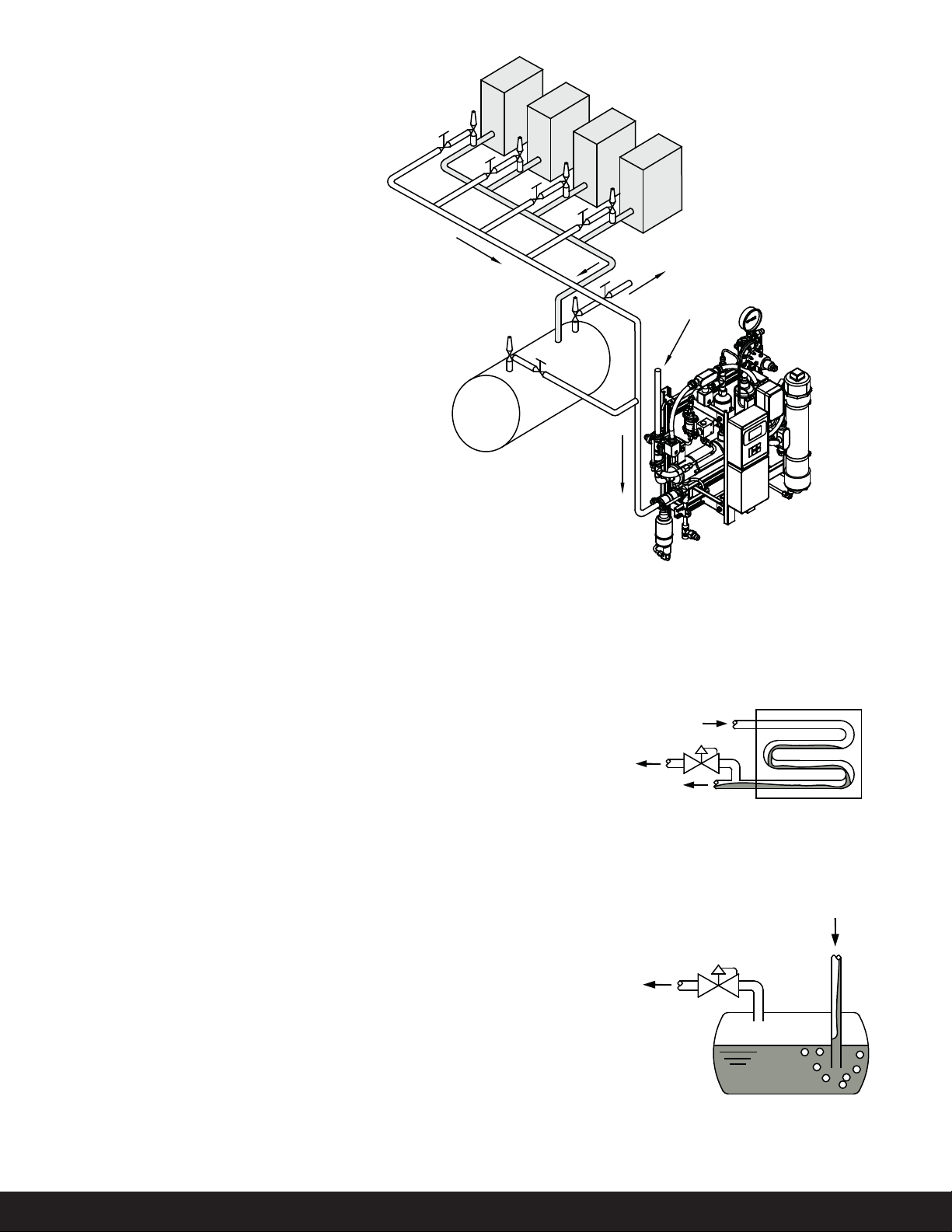
Purge Points (P)
V200 Auto Purger Multiple Purge Points
High
Pressure
Gas
Refrigerant
Foul
Gas
Liquid
Refrigerant
P
High Pressure Receiver
Purge Point
Liquid
Refrigerant
Foul
Gas
P
Introduction
Non-condensables like air, hydrogen,
nitrogen, and hydrocarbon gases
reduce the overall capacity of
the refrigeration system. Higher
pressures, which in turn causes
longer compressor runtime, longer
condenser fan runtime, higher
compressor discharge temperatures,
increase compressor power costs,
increase wear and tear on equipment,
increase leaks, reduce system
eciency, increase overall system
energy costs are all consequences of
non-condensables in the refrigeration
system.
In a refrigeration system non-
condensables can be introduced by:
• Inadequate system evacuation such
as servicing compressors, strainers,
valves, start-up, etc.
• Refrigerant additions
• Leaks from valve stem packings,
bonnet gasket, compressor shaft
seal, control transducers, etc.
• Separation of ammonia molecules
(hydrogen and nitrogen)
• Compressor oil breakdown
(hydrocarbon gases)
e base V200 Rapid Auto Purger
removes the non-condensable gases
from four purge points. With the
addition of up to two slave units, 36
purge points possible. is leads to
lower condensing pressure, runtime
of the compressors, and operating
costs.
Non-condensable indicators
are excessively high condensing
temperatures/pressures and
saturated temperature/pressure
deviations. One indicator is a higher
saturated condensing pressure/
temperature at the condenser for
the given outdoor air wet bulb
and heat rejection load. Another
indicator is the increasing dierence
between the observed condensing
pressure and the saturation
pressure corresponding to the liquid
refrigerant temperature exiting the
condenser.
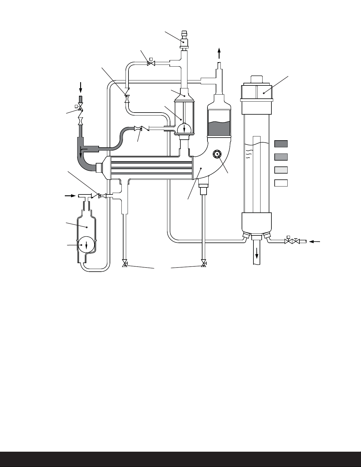
Purge Points
e most common purge points
in a refrigeration system are at the
condenser drain, pilot receivers,
thermosyphon receivers, high
pressure receivers, liquid drain
header, equalizing lines, and low
velocity-high side areas.
Purge points should be located to
ensure no liquid refrigerant is drawn
by the purger. e Auto Purger V200
has a liquid drainer at the foul gas
inlet to prevent any liquid refrigerant
from entering the shell side of the
heat exchanger.
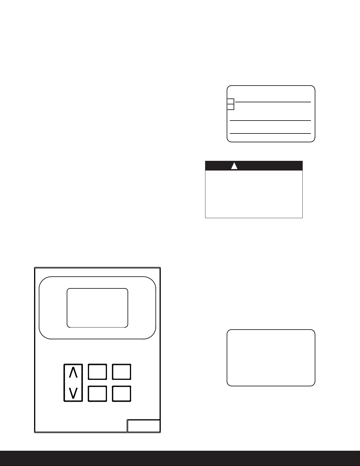
Auto Purging
e start of a purge cycle can
commence automatically, manually,
time based, central management,
and/or using the microprocessor. e
Auto Purger V200 can only purge one
point at any given time.
In automatic mode each purge point
is sampled for a minimum of ve
minutes. If the purge conditions are
not met within the sample time limit,
the Auto Purger continues to the next
purge point. When a purge point
meets the purge conditions within
the sample time limit the Auto Purger
starts the purge cycle. e purge
cycle shuts o when the non-purge
conditions are met.
Evaporative Condenser
Purge Point