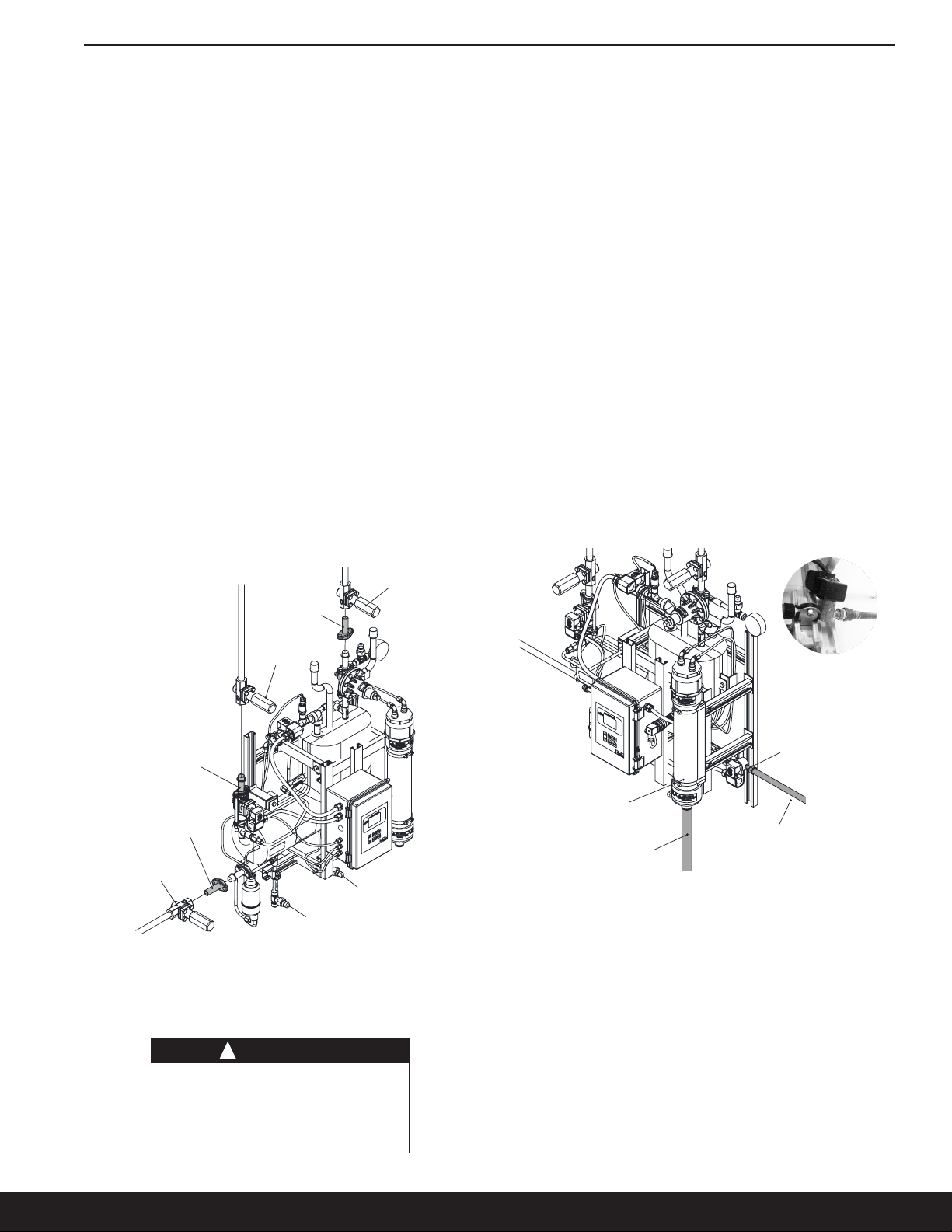
Parker V300 User manual

Contact Information:
Parker Hannin Corporation
Refrigerating Specialties Division
2445 South 25th Avenue
Broadview, IL 60155-3891
phone (708) 681-6300
fax (708) 681-6306
www.parker.com/refspec
Rapid Purger
Product Bulletin 76-00 B
Type: V300
Purpose:
The V300 rapid purger from Parker
is designed to safely and efciently
remove non-condensable gases
from ammonia refrigeration systems.
The V300 is an improvement over
the successful V200 series and
offers several new features and
benets.
The V300 is equipped with a
RS-485 communication port for
easy interface to controller data
transmission. All of the parameters
accessible via the HMI cable
are now accessible via the serial
channel. Further advancements
include extended data logging time
and password protection for factory
calibration settings.
Like its predecessor the V200, the
V300 can be used with 120 or 240
VAC and can handle from 4 to 20
purge points.
Product Features:
• Safety relief provision
• Made from 100% corrosion free
components
• RS-485 communication capability
• Records purge cycles and purge
time up to 12 weeks
• Password protection prevents
tampering
• Multiple language display
• Factory calibrated for plug and play
functionality
• Automatically adjusts vent
pressures based on system
conditions
• Proprietary microprocessor control
for all sensing
• Includes 1/2" Globe-T SW isolation
valves for the liquid, foul gas and
suction lines
• Includes a 30"-150 psig ammonia
gauge and encapsulated leaded
coils
• Ammonia loss history

Bulletin 76-00 B
2
High
Pressure
Receiver
Evaporative
Condensers
Auto Purger
(Model V300)
High Pressure
Liquid Main
Suction
Line
Liquid
Refrigerant
Line
Gas
Refrigerant
Line
Foul
Gas
Line
P
P
P
P
P
Table of Contents
Technical Data...............................................2
Introduction.................................................2
Purge Cycle. . . . . . . . . . . . . . . . . . . . . . . . . . . . . . . . . . . . . . . . . . . . . . . . . . 3
Installation ..................................................4
Startup Instructions ..........................................7
Nameplate Information ......................................7
Password Setting Instructions .................................8
Purge Type and Points Setting Instructions .....................9
Calibrate Pressure Input and RTD ............................11
Remote Communications Setup/Assembly Instructions ........12
Gearmo USB to RS485 Adaptor Driver Installation Instructions . 13
Remote Communications Setup Instructions - Option 1 ........14
Remote Communications Setup Instructions - Option 2 ........17
Technical Data
Liquid Temperature Range .......... -20°C to 50°C (5°F to 120°F)
Ambient Temperature Range ......... 2°C to 54°C (35°F to 130°F)
Suction Temperature Range...........-29°C to 4°C (-20°F to 40°F)
Maximum Rated Pressure ....................21.0 bar (305 psig)
Suction Temperature Range (High) ......-8°C to 4°C (16°F to 40°F)
Suction Temperature Range (Low)....-29°C to -9°C (-20°F to 15°F)
120 Volt Purger -
Complete Unit
240 Volt Purger -
Complete Unit
Part
No.
Purge
Points Application Part
No.
Purge
Points Application
186540 4
Low Temp
186545 4
Low Temp
186541 8 186546 8
186542 12 186547 12
186543 16 186548 16
186544 20 186549 20
112150 4
High Temp
112155 4
High Temp
112151 8 112156 8
112152 12 112157 12
112153 16 112158 16
112154 20 186183 20
Communication Protocol....................................18
Maintenance Instructions ...................................19
Parts Kit Informaton ........................................20
Service Pointers. . . . . . . . . . . . . . . . . . . . . . . . . . . . . . . . . . . . . . . . . . . . . 22
Purge Point Initiation/Termination Instructions ...............25
Setting Communications and Unit Instructions ................27
Display Setting Instructions..................................28
Language Setting Instructions................................29
Date/Time Setting Instructions...............................29
Date/Time Format Setting Instructions .......................31
History Viewing Instructions .................................32
Clearing History Instructions ................................33
Factory Test Mode Instructions...............................34
Introduction
Non-condensable gases such as air, hydrogen, nitrogen and
hydrocarbons reduce the overall eciency of refrigeration
systems. e eects of non-condensable gases, in a refrigeration
system, increase the system operating pressures. ese in turn
negatively aect system performance. Increased compressor
discharge temperature, higher energy costs, reduced system
eciency, leaks due to higher pressures, and increased wear on
mechanical components are all negative consequences of non-
condensable gases in refrigeration systems.
e build-up of non-condensable gases in the system can be
attributed to several factors. ese include inadequate system
evacuation during service of system equipment, additions of
refrigerant, leaks through external seals on equipment as well as
refrigerant, and oil decomposition.
Common indicators of non-condensable gases in the system
are excessively high condensing pressure or temperature and
deviations in the pressure and temperature relationship at
saturation conditions. is can be determined by checking the
temperature and pressure relationship at a known point in the
system where the refrigerant is saturated, such as the condenser
drain legs or high pressure receiver, as illustrated in Figure 1.
Figure 1: Purge Point (P) Locations

Bulletin 76-00 B
3
Pressure Transducer
Suction
Line
Vent
Solenoid
Bubbler
Water Inlet
Water
Drain
line
Level
Sensor
Heat
Exchanger
Oil
Drain
Foul Gas line
Liquid
Drainer
Check Valve
w/ Orice
Liquid
Refrigerant
Line
Check
Valve w/
Orice
Liquid
Solenoid
w/ Check
Valve
& Orice
Vapor Vent
Flow
Controller
Check Valve
w/ Orice
Flow
Controller
Low Temp. Liquid
High Pressure Gas
Non-Condensable
Gases
Water
A higher temperature measured at this point, compared to the
saturation pressure, indicates the presence of non-condensable
gases in the system.
Purging non-condensable gas from a refrigeration system can be
accomplished manually, mechanically or automatically. Manual
purging generally involves personnel removing air from specied
purge “points” within the system through hand shut o valves
routed to a water bucket. Mechanical purging is achieved by use
of a device which will allow air to escape to a water reservoir
when air is present. e latter method is automatic purging,
which is generally achieved by the use of a self-contained system
incorporating microprocessor controls. ese are designed to
sample the non-condensable gases and refrigerant mixture and
purge when non-condensable gases are present.
Mechanical and automatic air purging units, commonly referred
to as “purgers”, are manufactured by several companies. Each
manufacturer’s purger operates in its own unique way. is article
will focus specically on the automatic purgers manufactured by
Parker Hannin Refrigerating Specialties Division.
e most common purge points in a refrigeration system are at
the condenser drain, pilot receivers, thermosyphon receivers,
high pressure receivers, liquid drain header, equalizing lines,
and low velocity-high side areas.
Purge points should be located to ensure no liquid refrigerant
is drawn into the purger. e Rapid Purger V300 has a liquid
drainer at the foul gas inlet to prevent any liquid refrigerant from
entering the shell side of the heat exchanger.
Figure 2: Purger Fill & Pre-Cool Cycle
Purge Cycle
e purge cycle consists of three main processes: ll & pre-cool,
separation of non condensable gases & refrigerant, and the safe
release of the non-condensable gases.
1. Fill & Pre-Cool (See Figure 2 for a graphic representation of
this c ycle)
is cycle begins with high pressure liquid ammonia feeding
through the liquid solenoid, check valve and orice (causing
expansion) into the V300’s heat exchanger. e liquid
solenoid stays energized until the level of ammonia in the
heat exchanger is sensed by the level sensor. e level sensor
is strategically located so that all of the tubes in the heat
exchanger are lled with liquid ammonia. is guarantees
the highest level of performance.
e V300 Rapid Purger will stay in the “Pre-Cool” mode until
the shell of the heat exchanger reaches a temperature of 4.4ºC
(40ºF) or lower. is is determined by the temperature of the
suction the purger is tied into. Once the purger reaches the
required temperature, the purger will enter the active mode.
To prevent a vacuum type situation, the A2B evaporator
pressure regulator, located on the return suction line, is set at
Figure 3: Purger Separation of Non-Condensable Gases &
Refrigerant Cycle
0.34 barg (5 psig). is will prevent the heat exchanger from
reaching temperature below -29ºC (-20ºF).
2. Separation of Non-Condensable Gases & Refrigerant (See
Figure 3 for a graphic representation of this cycle)
Once the ll and pre-cool cycle reaches the desired
temperature and liquid level, it selects a purge point and
commences a purge cycle by activating a solenoid located on
the high side of the system, as illustrated in Figure 1.
With an active purge point, the non-condensable gases and
refrigerant mix, also known as foul gas, enters the shell side
of the heat exchanger through the liquid drainer, check valve
and a ow control orice. Any liquid that has condensed in
the purge lines will collect in the liquid drainer and return
directly to the suction. If the foul gas line does not contain
condensed liquid and any remaining liquid in the liquid
drainer evaporates to the suction, the liquid drainer ow
control ball will prevent any foul gas from entering the
suction line by blocking the orice at the bottom of the liquid
drainer tank, forcing the foul gas through the ow control
orice.
*Graphics for illustration only.
* *

Bulletin 76-00 B
4
CLEARANCEZONE
4.7 in
[119.02 mm]
4.7 in
[119.02 mm]
LIQ
REFRIGERA
LI
PRESSURE
GUAGE
SUCTION
LINE
FOUL GAS
LINE
5.9 in
[151.02 mm]
15.2 in
[387.34 mm]
40.4 in
[1025.41 mm]
22.0 in
[558.80 mm]
MOUNTING POINT
16.3 in
[414.34 mm]
20.4 in
[517.53 mm]
MOUNTING POINT
33.6 in
[853.12 mm]
16.3 in
[413.61 mm]
119.02 mm
(4.7 in)
119.02 mm
(4.7 in)
151.02 mm
(5.9 in)
Foul Gas
Line
Liquid
Refrigerant
Line
Suction Line
Pressure
Gauge
558.80 mm
(22.0 in)
Mounting
Point
1025.41 mm
(40.4 in)
414.34 mm
(16.3 in)
517.53 mm
(20.4 in)
Mounting Point
413.61 mm
(16.3 in)
853.12 mm
(33.6 in)
387.34 mm
(15.2 in)
CLEARANCE ZONE
Pressure Transducer
Suction
Line
Vent
Solenoid
Bubbler
Water Inlet
Water
Drain
line
Level
Sensor
Heat
Exchanger
Oil
Drain
Foul Gas line
Liquid
Drainer
Check Valve
w/ Orice
Liquid
Refrigerant
Line
Check
Valve w/
Orice
Liquid
Solenoid
w/ Check
Valve
& Orice
Vapor Vent
Flow
Controller
Check Valve
w/ Orice
Flow
Controller
Low Temp. Liquid
High Pressure Gas
Non-Condensable
Gases
Water
Figure 4: Purger Release of Non-Condensable Gases
Figure 5: Purger Dimensional Information
After going through the control orice the foul gas passes
over the tubes in the heat exchanger and residual refrigerant
is condensed. Liquid accumulation in the shell side of
the heat exchanger continues until the level reaches the
dierential check valve, where the liquid is recycled back
to the liquid makeup side of the heat exchanger. is
“Recycling” of ammonia reduces the need to call for more
makeup refrigerant to maintain the liquid level on the tube
side of the heat exchanger.
e Rapid Purger V300 can only purge one point at any given
time. In the separation of non-condensable gases, purging is
done automatically and eectively with built in control features
such as purge sampling.
In automatic mode, each purge point is sampled for a minimum
of ve minutes. If the purge conditions are not met within the
sample time limit, the Rapid Purger continues to the next purge
point. When a purge point meets the purge conditions within
the sample time limit, the Rapid Purger starts the purge cycle.
e purge cycle shuts o when non-purge conditions are met.
3. Release of Non-Condensable Gases (See Figure 4 for a graphic
representation of this cycle)
Non-condensable gases will continue to accumulate in
the “Vapor Vent Float” chamber as it is separated from
the refrigerant. Once the volume of these gases in the
oat chamber rises past the target pressures, based on the
sampled temperature, the vent and water solenoids are
energized and the non-condensable gases are released into
the water bubbler. For safe disposal, the non-condensable
gases are diluted in the water.
Any oil that may collect in the V300 purger can be drained from
the two oil drains. Before draining the oil, shut-o the purger
and close the liquid and foul gas valves. Allow the purger to
pump out any remaining refrigerant and close the suction line
valve. Use normal oil draining precautions to prevent injury or
property damage
Installation
All purgers are packed for a maximum protection. Unpack
carefully. Check the carton to make sure all items are unpacked.
Save the enclosed instructions for the installer and eventual user.
Do not remove the protective coverings until the purger is ready to
be installed.
e V300 Rapid Purger includes three 1⁄2" socket weld (SW) shut-
off isolation valves used for the suction, liquid, and foul gas lines.
A 1⁄4" national pipe thread (NPT) 30-150 psig ammonia pressure
gauge is also included for monitoring the suction line.
The V300 Rapid Purger includes a provision for customers to have
the option to install Parker Safety Relief Valves. The recommended
safety relief valve is the SR1R which uses a 1⁄2" inlet connection and
a 3⁄4" outlet connection.
Once the purger is ready to be installed we recommend the
following installation procedure. These instructions are for a new
system installation. If the purger is being installed in an existing
system or replacing an existing purger, the high pressure liquid,
foul gas, and suction lines must be isolated and pumped out.
1. Mount the Rapid Purger to a wall or structure that can easily
handle its weight and installation hardware. e approximate
weight of the purger is 34.5 kg (76 lbs). Figure 5 provides
dimensional information for the mounting holes, line locations
and overall purger height, width and length.
If mounting the purger outside it is recommended that it be
protected from natural elements like the sun, rain, etc. e
outside ambient temperature cannot exceed a range of 2°C to
54°C (35°F to 130°F).
*Graphics for illustration only.
*

Bulletin 76-00 B
5
Foul Gas Line
Flange w/ Stub
High Pressure Liquid Line
Flange w/ Stub
Suction Line
Flange w/ Stub
1⁄2" SW
Shut-Off Valve
1⁄2" SW
Shut-Off Valve
1⁄2" SW
Shut-Off
Valve
Oil Drain Valve
(Shell Side)
Oil Drain Valve
(Tube Side)
Water
Line
1⁄4" NPT
Water Solenoid
Bubbler
3⁄4"-14 FPT
Water Drain Line
Under Side View: Water
line connected to the water
solenoid
WARNING
Do not trap the foul gas line prior to
entering the purger. is will cause
the foul gas to condense.
!
Figure 6: Purger Flange Line Connections
Figure 7: Water Line Connections
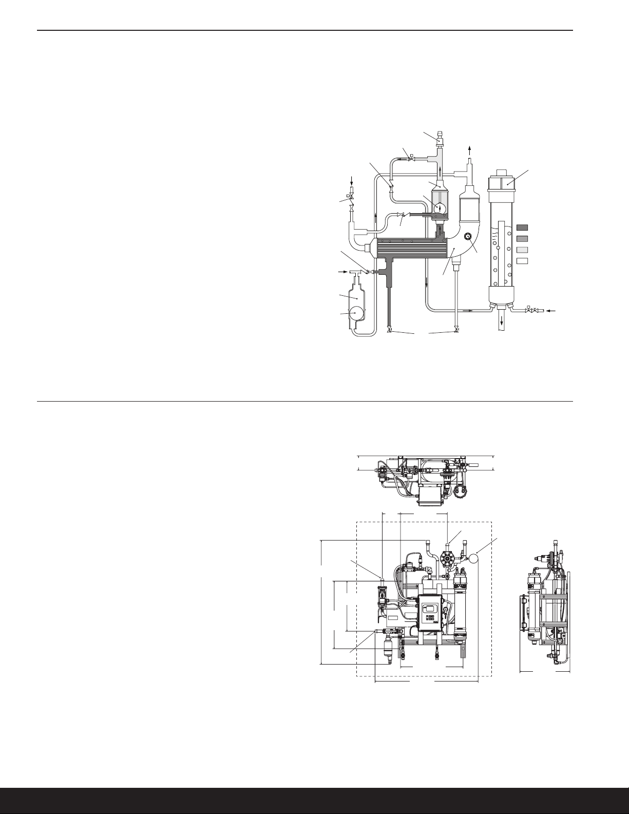
Make sure to leave access for servicing the unit if required. e
recommended clearance zone, as shown in Figure 5, is 254 mm
(10") for the top and sides. e bottom of the purger must be
free of obstructions to allow for water drain and oil removal.
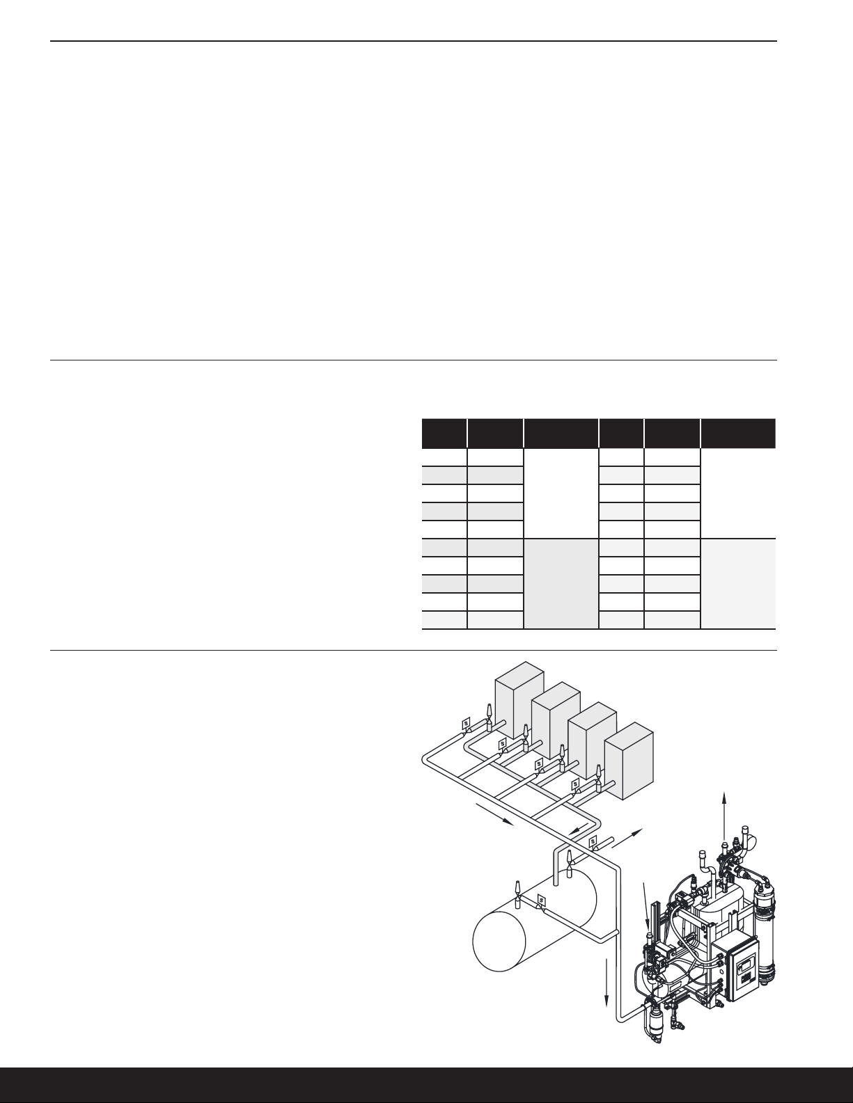
2. Properly locate, support and align the systems high pressure
liquid, foul gas and suction lines with the purger.
Note: To prevent oil from entering the heat exchanger and
reducing performance of the purger, it is recommended to
tie the liquid line in from the side or top of the desired liquid
piping. We also recommended connecting the suction line
from the purger to the low side system suction. is will allow
setting of the A2 regulator for optimal performance down to a
minimum of 0.34 barg (5 psig).
3. Weld in the three 1⁄2" SW shut-off isolation valves. Make sure
the connections are free from debris and corrosion. For more
installation instruction on hand shut-off valves, refer to the
RSBHV safety bulletin located in the purger packet.
Before welding the system’s high pressure liquid, foul gas and
suction lines to the hand shut-off valves, they need to be in the
open position. Normally, it is not necessary to disassemble
valves for welding. However, if welding is prolonged enough
to overheat the body, a wet rag should be wrapped around
the valve bonnet and upper body during welding. e codes
applicable to the welding of socket weld valves require that
the pipe be inserted into the socket until bottomed against the
stop. e pipe is then to be backed out approximately 1⁄16 of an
inch before welding.
4. Remove the purger flange connections, with the welded stubs,
from the high pressure liquid, foul gas and suction line. e
anges are highlighted, in gray, in Figure 6.
5. Wait several minutes before welding the purger anges to
the hand shut-o valves. Be certain the mating surface of the
ange is parallel to the mating ange and perpendicular to the
pipe axis. Again, the hand shut-off valves must be in the open
position prior to welding. Check the connections to make sure
they are free from debris.
6. After the shut-o valves and purger anges have been installed
wait several minutes to cool down from the welding process.
e hand shut-o valves must be put in the closed position to
prevent any ammonia from entering the heat exchanger prior
to nishing the installation. If the valves are closed before the
heat dissipates from the welds, the seat can be damaged.
7. Using the same ange nuts and bolts, reconnect the anges
to the purger and tighten them progressively. For more
information on ange torque specication, please reference
the IIAR 2-2008 Section 10 documentation.
8. Purge the water line to remove any contaminants prior to
connecting it to the water feed solenoid, highlighted in gray in
Figure 7. is will prevent the solenoid valve, ow switch and
water lines from becoming plugged. Apply Teon tape/paste to
the 1⁄4" NPT threaded nipple prior to threading it into the water
solenoid.
9. Install a water drain line for the bubbler. e connection for
the drain line is 3⁄4"-14 FPT. Follow your local codes on how to
properly dispose of the water after a purge.
10. Check and verify both oil drain valves, shown in Figure 6, are
closed by removing the seal cap and turning the adjustment
stem clockwise. If the adjustment stem does not move it means
the valve is fully seated. Do not over tighten; it can damage the
seat and be a potential leak point.
11. Open the purger control panel to start wiring the purge points
and power supply, see Figure 8 for wiring diagram. All common
lines should tie together at the DIN rail terminal blocks.
Coil common, shown in Figure 8, on the purge point solenoids
connections are common to the relay. Incoming line power
(120/240 volts) should be supplied to these terminals. An
incoming neutral should be supplied to one of each of the coil
Table of contents
Other Parker Auto-purger manuals
Popular Auto-purger manuals by other brands

Spectron
Spectron BE55+56-SP user manual

Pepperl+Fuchs
Pepperl+Fuchs 6500 Series instruction manual

SeaSTAR
SeaSTAR POWER PURGE JR HA5445 quick start guide

Hansen
Hansen AUTO-PURGER M Service instructions

BPS
BPS YZ102 Installation & operation manual

Redi Controls
Redi Controls Redi-Purge PRG-113-C3 Installation, operation & maintenance manual