Hansen AUTO-PURGER M Operating instructions

SECTION 1 MOUNTING & PIPING INSTALLATION
An APM is usually installed in the compressor room where
it can be monitored, but also may be installed outdoors
where temperatures below freezing are not anticipated.
The APM comes standard with a watertight NEMA 13 (IP65,
Category 2) control cabinet enclosure with sealed conduit
wiring. Any unused electrical entrances to the enclosure
must be sealed to protect electronics from moisture. A
NEMA 4 cabinet enclosure is available.
An optional valve package (VPM) for purger isolation is
available from Hansen. This consists of three welded
assemblies which include shut-off valves, gauge valves,
and mating flanges. An illustration detailing this optional
valve package is on page 12 (Figure 13).
FOUL GAS PIPING
Purging at several points, up to four with the APM, on the
high-pressure side of the system is the best method for
removing foul gas. Foul gas is refrigerant gas containing
some air or other noncondensibles. Several points should
be used because it is nearly impossible to predict where
noncondensible gas will accumulate in a system.
Even for multipoint purging, only one purge point should be
purged at a time. Connecting two purge points from two
condensers or receivers may result in gas flowing from one
condenser to another. This is due to an unequal pressure
drop, even though the differences in pressure drop are
very small, for example ¼ psig (0.02 bar). The result would
be that, even in the best of circumstances, only one point
is effectively purged. The best practice is to purge each
condenser and receiver circuit separately.
When utilizing multipoint purging, the purge point solenoid
valves can be manifolded into one foul gas line to the
purger. A ½" (13 mm) size line is the minimum and should
be pitched toward the purger to drain any condensed
liquid. Also, no liquid traps are allowed either before or
after the purge point solenoid valves (See Figure 2). The
foul gas line should not pass through cold areas where
INTRODUCTION
The AUTO-PURGER® M is a compact and totally automatic,
electronically-controlled, noncondensible gas refrigerant
purger for reducing condensing pressure, and thereby
saving electrical energy used by the refrigeration system.
This deluxe purger is preassembled, prewired, tested,
insulated, and includes an automatic water bubbler.
Installation requires piping the foul gas line, liquid line,
suction line, water line, drain line, and wiring the power
connection and the remote ½" (13 mm) port purge point
solenoid valves, which must be purchased separately. Up
to four (4) purge points can be controlled by this purger.
The AUTO-PURGER® M (APM) features welded piping
and watertight electrical construction. The APM meets
the requirements of the Canadian Standards Association
(CSA certified).
A typical APM installed in a plant with normal-entering
noncondensible loads will handle up to a 200 ton (700 kW)
system. Each purge point will be active between 10 and 30
minutes, depending on the noncondensible gas presence
(mostly air) and the purger mode of operation.
Model APMF AUTO-PURGERS are for use in halocarbon
refrigeration systems. The installation and operation of
these AUTO-PURGERS are similar to that of an ammonia
AUTO-PURGER M. See page 13 for additional details.
MOUNTING INSTRUCTIONS
Mount the APM straight and securely on a wall or sturdy
steel channels capable of supporting 350 lbs (160 Kg). Eight
mounting holes in the frame are provided to support the
purger (See Figure 1). The APM should be located in an
accessible area, but away from the movement of equipment
that could accidentally damage the purger. Elevation with
respect to condensers or high-pressure receivers is not
critical, however, purge point solenoid valves must be
above the purger.
Specifications, Applications,
Service Instructions & Parts
AUTO-PURGER®M
“Energy Saver”
Compact, Non-condensible
Gas (Air) Purger
Bulletin APM-001e
AUG 2015
For Models APM & APMF
Model APM

2
APM-001e
AUG 2015
further condensing of the saturated gas can occur. If this
cannot be avoided, the line must be insulated because
flooded purge point lines result in flooding the APM with
liquid, causing a temporary halt of noncondensibles
being removed. If flooding can not be avoided, additional
condensate drainage may be necessary.
It is important that all purge points be located above any
liquid surfaces to avoid drawing liquid refrigerant, rather
than vapor, into the APM.
EVAPORATIVE CONDENSER PIPING
Typically, evaporative condenser outlet liquid drain lines
on each circuit must drop a minimum of 4 feet (1.2 m) for
ammonia from the centerline of the evaporative condenser
outlet to the centerline of highest elevation of the liquid
line manifold to receiver. Preferably, each circuit should
have a P trap to balance variations in pressure drop in each
circuit to prevent liquid from backing up into one or more
condensers, and thereby flooding the purge point. Most air
from the system will normally be trapped between the
condenser and the P trap. Also, a properly-sized equalizer
line from the receiver will help drain condenser circuits
into the receiver. Refer to ASHRAE GUIDELINES or IIAR
Papers on condenser piping design. Hansen Technologies
can provide copies of these articles. Also, consult the
condenser manufacturers’ installation instructions for
additional piping and sizing information.
On evaporative condensers, avoid using one purge point
solenoid valve to purge two circuits. This practice negates
the P-trap on the condenser drain line because of the
purge connections of the two circuits and may back liquid
up into one circuit.
ACTIVE PURGE POINT
1234
ENERGY SAVER
R
HANSEN TECHNOLOGIES
CORPORATION
(25)
(298)
ON HIGH PRESSURE CONDENSERS AND RECIEVERS
PROTECTED SUCTION ACCUMULATOR
(24)
(86)
(192)
TYPICAL
(16)
(508)(813)
(152)
FOR POWER CONNECTION
FOR REMOTE PURGE POINT
SOLENOID VALVE CONNECTIONS
(86)
(359)
(49)
(457)
OIL DRAIN CONNECTION (3/8" FPT)
TYPICAL
(16)
(14)
MOUNTING HOLE
8 PLACES
(59)
(130)
(178)
SHUT-OFF VALVE CONNECTION
PRESSURE RELIEF VALVE
(406)
(464)
CONNECTION
1" PVC DRAIN
WALL OR COLUMN
18.25"
BUBBLER
CONTROL CABINET
1/2" CONNECTION FOR OPTIONAL
1/2" FPT WATER LINE
7.00"
3/4" SUCTION LINE
5.11"
0.53" DIA
0.62"
18.00"
HIGH PRESSURE SEPARATOR
LOW PRESSURE SEPARATOR
1.93"14.13"
3/4" CONDUIT KNOCK OUT
1/2" CONDUIT KNOCK OUT
6.00"
32.00"
20.00"
0.62"
3/4" SUCTION LINE CONNECTION TO
1/2" HIGH PRESSURE LIQUID LINE CONNECTION
1/2" FOUL GAS'' LINE CONNECTION FROM PURGE POINTS
''
3.38"
16.00"
2.31"
1.00"
0.94"
3.38"
7.56"
11.75"
1.63" (41 MM)
INSTALLATION DIMENSIONS (MM)
Figure 1
FROM FOUL GAS SOURCE
CLOSE-COUPLED
ISOLATION
TO PURGER
1/2" (13 MM) PORT
SHUT-OFF VALVE
REMOTE PURGE POINT
SOLENOID VALVE
ISOLATION SHUT-OFF VALVE
STRAINER
(GLOBE VALVE STEM HORIZONTAL
IS PREFERRED)
LEVEL OR
PITCH DOWN
SECTION 1 MOUNTING & PIPING INSTALLATION

3APM-001e
AUG 2015
ACTIVE PURGE POINT
1234
ENERGY SAVER
R
HANSEN TECHNOLOGIES
CORPORATION
(25)
(298)
ON HIGH PRESSURE CONDENSERS AND RECIEVERS
PROTECTED SUCTION ACCUMULATOR
(24)
(86)
(192)
TYPICAL
(16)
(508)(813)
(152)
FOR POWER CONNECTION
FOR REMOTE PURGE POINT
SOLENOID VALVE CONNECTIONS
(86)
(359)
(49)
(457)
OIL DRAIN CONNECTION (3/8" FPT)
TYPICAL
(16)
(14)
MOUNTING HOLE
8 PLACES
(59)
(130)
(178)
SHUT-OFF VALVE CONNECTION
PRESSURE RELIEF VALVE
(406)
(464)
CONNECTION
1" PVC DRAIN
WALL OR COLUMN
18.25"
BUBBLER
CONTROL CABINET
1/2" CONNECTION FOR OPTIONAL
1/2" FPT WATER LINE
7.00"
3/4" SUCTION LINE
5.11"
0.53" DIA
0.62"
18.00"
HIGH PRESSURE SEPARATOR
LOW PRESSURE SEPARATOR
1.93"14.13"
3/4" CONDUIT KNOCK OUT
1/2" CONDUIT KNOCK OUT
6.00"
32.00"
20.00"
0.62"
3/4" SUCTION LINE CONNECTION TO
1/2" HIGH PRESSURE LIQUID LINE CONNECTION
1/2" FOUL GAS'' LINE CONNECTION FROM PURGE POINTS
''
3.38"
16.00"
2.31"
1.00"
0.94"
3.38"
7.56"
11.75"
1.63" (41 MM)
TYPICAL APPLICATION
Figure 2
FROM FOUL GAS SOURCE
CLOSE-COUPLED
ISOLATION
TO PURGER
1/2" (13 MM) PORT
SHUT-OFF VALVE
REMOTE PURGE POINT
SOLENOID VALVE
ISOLATION SHUT-OFF VALVE
STRAINER
(GLOBE VALVE STEM HORIZONTAL
IS PREFERRED)
LEVEL OR
PITCH DOWN
SECTION 1 MOUNTING & PIPING INSTALLATION
PURGE POINT VALVE (TYPICAL)
Figure 3

4
APM-001e
AUG 2015
PURGE POINT CONNECTIONS
Foul gas lines from condensers should be purged at points
recommended by the condenser manufacturer. Usually, this
is at the top of each circuit’s outlet header which drains
down through a P-trap to the receiver. In some cases, a
small high pressure auxiliary receiver is located at the
outlet of one or more condensers. This receiver should
have a purge point at the top, preferably at a “dead” area
away from condenser drain pipes. Below is a typical valve
arrangement for a purge point (Figure 3). Regardless of
the purge point location, it is absolutely necessary to
ensure that liquid is not drawn into the foul gas line.
WATER LINE
The APM has an automatic water bubbler to eliminate any
water bottle attention. Connect the water supply to the
purger water shut-off valve (See Figure 1). Water pressure
should be between 30 and 80 psig (2 and 5 bar). The
factory-installed flow controller limits the amount of water
going into the bubbler.
The transparent tube of the water bubbler may become
coated with mineral deposits after a period of time. These
deposits can be removed by adding a cup of vinegar to the
water in the bubbler and cleaning the clear tube through
the top plastic fitting with the brush supplied. A water
conditioning filter cartridge and housing are available for
abnormally hard water.
DRAIN LINE
A 1” PVC socket water drain connection is located at the
bottom of the bubbler (an alternate 1” FPT threaded adapter
is also supplied). The water should flow to a suitable drain.
Initially, fill the water bubbler with water via the threaded
plug located at the top of the bubbler. Keep the plug
lubricated and hand tight. A circular, thin, plastic “stick-
on” acts as a bubbler relief device in case of water drain
plugging. The drain line should be supported to prevent
undue stress on the water bubbler.
OIL DRAINS
There are two 3/8” valve oil drain connections near the
bottom of purger (see Figure 1) from which oil can be
drained. These valves are fitted with 5/16” (8 mm) hex
socket plugs. Before draining oil, first close the liquid and
foul gas lines to prevent additional liquid from entering the
purger. Wait approximately one half hour and then turn
the purger off. Allow the purger to pump out, then close
the suction line shut-off valve. Use normal refrigerant oil
draining precautions to prevent human or property damage.
In general, oil will not be a problem unless the liquid line
is connected to a vessel or line where oil can enter the
purger. See also the Caution section on page 14. Escaping
refrigerant may cause personal injury, particularly to the
eyes and lungs.
LEAK TEST
Use standard refrigeration procedures to check the APM
for leaks before placing it into service. See also the
Caution section on page 14. Manually open one purge
point solenoid valve. Open the foul gas line shut-off valve
and wait a few moments for the flooded evaporator to
pressurize through the metering orifice. Allow pressure to
build to condensing pressure, as shown on the high side
pressure gauge. Close the foul gas line shut-off valve and
check the purger for leaks.
Where a high-pressure float regulator is used to drain one
or more condensers, the top of the float valve chamber
should also be a purge point.
Horizontal shell and tube water-cooled condensers, and
heat exchangers should be purged at the top, usually at
the point(s) furthest from the compressor discharge main
inlet.
Vertical condensers should be purged near the top of the
vessel if possible.
For certain types of oil separators where very low velocities
may exist near the top of the vessel, purging may be
advisable from a top fitting.
It is normally not advisable to purge controlled pressure
receivers, high-pressure thermosyphon vessels, or vessels
located on the low side of the system.
SUCTION LINE
The ¾” suction line from the purger should be connected
to a protected main suction line or a suction accumulator.
Install a suction line isolation shut-off valve near purger.
Excess amounts of liquid from the purger evaporator may
occasionally be transmitted through the suction line. The
suction temperature must be 40°F (4.4°C) or less to satisfy
the APM temperature sensor before purging will occur.
LIQUID LINE
A high-pressure ½” liquid line is required for the APM. The
connection to the high-pressure liquid source should be
a location where oil will not be directed into the purger.
Install liquid line shut-off valve near the purger. The liquid
line supplies refrigerant during start-up and feeds make-
up liquid as required. The only requirement is the liquid
supply pressure must be sufficiently above the purger
evaporator pressure, usually greater than 60 psi (4.1 bar).
During operation, only 5% of the liquid refrigerant required
for cooling comes from the liquid line. The remainder of
the refrigerant is condensate from the foul gas line, which
is collected in the drain, condensed in the coil, and into
the evaporator.
SECTION 1 MOUNTING & PIPING INSTALLATION

5APM-001e
AUG 2015
ELECTRICAL CONNECTIONS
The standard electrical requirement for the APM is 115V
50/60 Hz. Also available is 230V 50/60 Hz. Main supply
voltage fluctuations should not to exceed ± 10% on nominal
voltage. Connect APM to a dual pole external switch or
circuit breaker suitable for full disconnection. Locate this
switch or circuit breaker nearby. The control cabinet has
a bottom ½” knockout for power connection and bottom
3/4” knockout for individual purge point solenoid valves
(See Figure 4). Any additional knockouts, if necessary,
should be made on the bottom of the control cabinet. A
grounding block inside the control cabinet is provided for 3
wire purge point solenoid coils. Carefully study the wiring
diagram below (Figure 5) to avoid electrical short circuits.
Connect electrical wiring from each purge point solenoid to
the remote purge point solenoid plug-in connector screw
terminals (1 through 8) plus the grounding block. Normally,
the voltage of the remote purge point solenoid valves is the
same as the purger. However, if the purge point solenoid
valve coil voltage is different, simply remove and discard
the factory installed jumpers between terminals 13 & 14 and
15 & 16. Bring the purge point solenoid line (L1) connection
to terminal 14 and neutral (L2) to terminal 16.
SECTION 2 ELECTRICAL INSTALLATION & OPERATION
RESET PINS
NLLLN NNLLN
PRESSURE TRANSDUCER
PLUG-IN CONNECTORPOWER BOARD
COAXIAL CONNECTORS 1/2'' KNOCKOUT
POWER / INTERLOCK
PLUG-IN CONNECTOR
GROUNDING BLOCK
POWER BOARD
REPLACEABLE 3 AM
P
REMOTE PURGE
POINT SOLENOID
REPLACEABLE 3 AM
P
PURGER SOLENOID
PLUG-IN CONNECTOR
CONTROL BOX LATCH
CONTROL BOARD
CONTROL BOAR
D
1
PLUG-IN CONNECTOR
TEMPERATURE SENSOR
3/4'' KNOCKOUT
REMOTE PURGE
POINT SOLENOID
PLUG-IN CONNECTOR
2
3FUSE (P/N 20-1698)
FUSE (P/N 20-1698)
2-LOW SIDE LEVEL SENSOR
1-DRAINER LEVEL SENSOR
3-HIGH SIDE LEVEL SENSOR
PURGE POIN
T
ENABLE SWITCHES
F6A
F6B
CABL
E
RTV SILICONE SEALANT
AND SHIELD
GROUNDING WIRE
CONTROL CABINET (INSIDE VIEW)
Figure 4
WIRING DIAGRAM
Figure 5
16151413121110987654321
#1 #2 #3 #4
PURGE POINT SOLENOID VALVES
#1
FACTORY-INSTALLED JUMPER
S
OPTIONAL INTERLOCK
(REMOVE JUMPER IF USED)
#2 #3 #4
POWER BOARD
FIELD INSTALLED WIRING
LINE
NEUTRAL
LINE VOLTAGE
POWER BOARD REPLACEABLE
3 AMP TYPE F FUSE (P/N 20-1698) REPLACEABLE 3 AMP TYPE F FUSE
REMOTE PURGE POINT SOLENOID
(P/N 20-1698)

6
APM-001e
AUG 2015
FEATURES OF THE APM
The purger can be set to one of several operating modes
to suit the requirement of the system. These include:
Automatic Operation, Manual Operation, New System Start-
up, and Purger Switched Off. The mode of operation can
be selected by repeatedly pushing the program advance
button on the front panel until desired purger mode light
is on. (See Figure 6).
AUTOMATIC OPERATION
The Automatic Operation mode is where the purger should
be set when normal levels of noncondensibles are in the
refrigeration system. The microprocessor-based electronics
of the APM uses its “logic” to locate noncondensibles
and spend more time purging those points. The purger
will energize the first enabled purge point solenoid (see
page 7, Purge Point Enable Switches). If after 10 minutes
noncondensible gases are not released, the purger then will
advance to the next enabled purge point. If noncondensibles
are released at any purge point within the first 10 minutes,
then the purger will continue to process gas and remain at
that purge point for increments of 10 minutes as long as
noncondensible gas is released during the 10 minute time
period. This “smart” feature will continue for a maximum
of 30 minutes. After 30 minutes, the purger will go on to
the next active purge point regardless if noncondensibles
are released. Once noncondensible gases have been
minimized, and enabled purge points cycle without releasing
noncondensibles, the purger will go into “Standby” mode
for two hours (the Standby purger status light will be on).
After two hours on Standby, the purger will then resume
operation to seek out noncondensible gases that may
have collected.
MANUAL OPERATION
Manual Operation mode allows the operator to select one
purge point continuously. This is usually the case if a
large volume of noncondensible gas is suspected to be at
a particular point. To select this mode, push the program
advance button until the Manual Operation purger mode
light is on. Then, push the purge point advance button to
select the purge point. In this mode, the purger will purge
this point only. However, noncondensibles must be present
for the purger to release gas from the purger. If not, the
purger will go into Standby mode.
NEW SYSTEM STARTUP
The New System Startup mode is to be used when the
refrigeration system is known to contain large amounts
of noncondensible gas. This may be due to new system
startup, extensive repairs to a system, or the presence of
an abnormal vacuum leak on the low side of the system.
The APM automatically sequences the purge point solenoid
valves for a fixed period of 10 minutes each to remove air
from each of the enabled purge points. The purger will
not go into Standby mode while in New System Startup
mode.
PURGER SWITCHED OFF
When the purger is in this position, all solenoid valves close
and the purger will pump out if the suction valve is open.
CONTROL CABINET (FRONT VIEW)
Figure 6
HANSEN TECHNOLOGIES
CORPORATION
PURGE
POINT
ADVANCE
PROGRAM
ADVANCE
PURGING
STANDBY
SEE DIAGNOSTICS ON RIGHT SIDE OF ENCLOSURE
MANUAL OPERATION
NEW SYSTEM STARTUP
PURGER SWITCHED OFF
PURGING LOG (MINUTES)
(DIAGNOSTIC CODE WHEN FLASHING)
ZERO
RESET
ACTIVE PURGE POINT
AUTOMATIC OPERATION
ENERGY SAVER
1234
R
RESET BUTTON
PURGING LOG
POINT LIGH
T
ACTIVE PURG
E
PURGER
MODE LIGHTS
CONTROL CABINE
T
ENCLOSURE
ADVANCE BUTTON
PURGE POINT
BUTTON
PROGRAM ADVANC
E
STATUS LIGHTS
PURGER
DIGITAL READOUT
(TYPICAL
)
SECTION 2 ELECTRICAL INSTALLATION & OPERATION

7APM-001e
AUG 2015
ACTIVE PURGE POINT
The front of the control cabinet has lights which indicate
the active purge point. The active purge point can be
manually advanced in any operational mode by pushing
the purge point advance button.
PURGER STATUS LIGHTS
There are two purger status lights on the front of the control
cabinet next to the digital readout. These are the Purging
status light and Standby status light which indicate when
noncondensible gas (air) is being released from the purger
(Purging), or when the purger is in a waiting mode (Standby).
PURGING LOG
The purging log is displayed on the digital readout. It
displays the number of minutes the purge gas solenoid valve
(C) (see Figure 11) has been open to release noncondensibles
into the water bubbler.
The purger log can be used to track the release of
noncondensible gas. If a daily or weekly record is kept, then
any abnormal increases in the amount of noncondensible
gases can be noted, and corrective measures can be taken.
Little or no activity compared to normal operation may
indicate noncondensibles have been thoroughly removed
or a problem with the purger. Frequent activity beyond
normal could mean excessive new leakage of air into the
system. To reset the purge log, push the zero reset button
next to the digital readout on the front panel.
DIAGNOSTIC FEATURES
Although the APM is very reliable, after an extended
operation or under severe conditions, problems may
occur or be suspected. Under these conditions, due to
the importance of the purging functions, restoration to
normal operation is desired as quickly as possible. The
APM features diagnostic codes which are displayed on the
digital readout when abnormal operation of the refrigeration
system or the APM is detected. These flashing numbers
help to identify the problem area. Below is a quick reference
to these diagnostic codes. The digital readout will display
the diagnostic code related to the occurrence which first
put the APM into this mode; exception, 6666 will override
7777. Also see the troubleshooting guide on page 10 for
detailed explanation.
Flashing 2222 LOSS OF FOUL GAS PRESSURE.
Flashing 3333 PURGER TOO WARM.
Flashing 4444 PURGED OVER 60 MINUTE TIME LIMIT.
Flashing 5555 PURGER SHUT-OFF REMOTELY.
Flashing 6666 LEVEL CONTROL OUT OF RANGE.
Flashing 7777 LOSS OF HIGH-PRESSURE LIQUID.
PURGE POINT ENABLE SWITCHES
These switches are located on the control board and are
all factory-set to the ON position. They control whether
or not a purge point can become active. If for example,
only three purge points are being utilized, the number 4
purge point enable switch should be in the downward off
position (see Figure 7). By doing this, the unused purge
point is disabled and purger time is not wasted.
PUMP OUT PROCEDURE
Performing certain types of service on the APM may first
require the purger to be pumped-out (drained of liquid
refrigerant). To begin pump-out, shut off the foul gas
and high-pressure liquid lines. Wait for all refrigerant to
evaporate to suction; this usually takes several hours to
complete. Using safe refrigeration practices, reduce the
pressure to zero. In addition to following these procedures,
check the lower portion of drainer and the APM piping for
signs of frost. If there is no frost, pump-out is probably
complete. If there is frost, this means excess refrigerant
is still in the drainer and/or piping. To drain, energize the
drainer solenoid valve.
To accelerate the pump out process, attach ammonia hoses
to the oil drain valves. Close the main suction line to the
purger. Using the oil drain valves, pump out to a lower
suction pressure than the main purger suction line. When
pumped out, close the oil drain valves and leave the main
suction line closed to isolate the purger. With electricity
on, the pressure in the purger should remain at zero. This
process should be completed only by knowledgeable
refrigeration technicians.
CONTROL BOARD
Figure 7
SECTION 2 ELECTRICAL INSTALLATION & OPERATION

8
APM-001e
AUG 2015
SOLENOID VALVES
The APM is equipped with four solenoid valves. These are:
the liquid drainer solenoid valve (A), the liquid line solenoid
valve (B), the purge gas solenoid valve (C), and the water
solenoid valve (D). See Figure 11. With the exception of the
water solenoid valve, each is directly welded in-line and
has a stainless steel removable seat/orifice (see Figure 8).
The removable seat/orifice facilitates easy access to the
orifice for inspection or replacement. If necessary, the
water solenoid valve (D), whose brass body has threaded
ends, can easily be replaced or parts thereof changed.
Figure 8
LIQUID DRAINER
The liquid drainer removes any condensed liquid that trickles
from the foul gas line into the purger. This enables the
purger to always be condensing gas, rather than having
liquid entering the condensing section of the purger and
limiting proper operation. The drainer solenoid valve (A)
will open to empty a reasonable amount of excess liquid
directly to the flooded evaporator. However, if too much
liquid comes down the foul gas line, due to improperly
piped condensers, corrective action must be taken. See
the Foul gas piping section on page 3.
STRAINER/ORIFICE
The strainer/orifice meters condensed liquid refrigerant
from the high-pressure side of the purger into its flooded
evaporator. It features a dual filter arrangement to reduce
potential orifice blockage. This dual filter (strainer) removes
particles and houses the integral orifice (strainer/orifice
screen assembly). See Figure 10.
In addition, separate remote point solenoid valves are
required, one for each enabled purge point. These are not
included with the APM. The Hansen type HS8 solenoid
valve having a ½” (13mm) port and a stainless steel piston
is recommended. Below is a typical purge point solenoid
valve with close-coupled strainer (Figure 9).
Figure 9
REMOVABLE
SEAT/ORIFICE
CHECK VALVES
There are three check valves on the purger. An 80 psid
(5.5 bar) differential check valve is installed on the purge
gas line to prevent any possibility of reverse flow of water
into the purger. A 225 psid (15.5 bar) differential relief
check valve leads from the condensing coil inlet to the
suction line; this prevents excessive purger pressure. A
third check valve is installed from the liquid drainer to the
evaporator coil to prevent reverse flow with a temporary
loss of foul gas pressure.
WATERTIGHT
ENCAPSULATED
COIL
STAINLESS
STEEL PISTON
MANUAL OPENING
STEM
CLOSE-COUPLED
STRAINTER
REMOVABLE SEAT
ORIFICE
WATER BUBBLER
The APM is equipped with a water bubbler which eliminates
any water bottle attention. Purge gas (noncondensibles)
from the purger flows into the bottom of the water bubbler
where residual ammonia can be absorbed into the water.
The water with absorbed ammonia flows to a drain. The
water solenoid valve (D) opens to automatically replenish
water to the bubbler each time the purge gas solenoid
valve (C) energizes. A 30-second delay keeps the water
solenoid valve (D) open after the purge gas solenoid valve
(C) de-energizes to refill water bubbler. Proper release of
noncondensibles through the bubbler is usually indicated
by large, 1/2" (13mm) diameter bubbles.
STRAINER/ORIFICE
SCREEN ASSEMBL
Y
STRAINER/ORIFICE
BODY
STRAINER/ORIFICE
BODY
STRAINER/ORIFICE
SCREEN ASSEMBLY
SECTION 2 ELECTRICAL INSTALLATION & OPERATION
Figure 10

9APM-001e
AUG 2015
The APM is designed to automatically start-up and operate
without the assistance of plant personnel. Beginning at
start-up, the following is a description of the refrigerant
flow through a purger.
Keep the control cabinet door closed at all times to
prevent water damage and tampering.
PURGER START-UP SEQUENCE
On start-up, liquid refrigerant fills and begins to cool the
purger. The liquid line solenoid valve (B) energizes to
feed refrigerant to the flooded evaporator. The low side
level sensor, located on the side of the flooded evaporator,
senses when liquid reaches the proper level. The display
should show 3333.
At the same time the flooded evaporator is filling, foul
gas enters the flooded evaporator condensing coil and
the refrigerant gas contained therein changes state to a
liquid. The liquid and noncondensible gas gradually fill
the air separator chamber.
As the purger continues to cool down, a temperature sensor
attached to the flooded evaporator senses temperature.
At approximately 40°F (4.4°C) evaporator temperature, the
readout will no longer display 3333 and the purger will
enter the mode selected.
Foul gas is continually processed as long as a remote
purge point solenoid is energized. It is important that
one, but only one, remote purge point solenoid valve is
open at all times to prevent losing foul gas pressure to the
purger. If foul gas pressure is lost (as sensed by pressure
transducer), diagnostic code 2222 flashes on the APM
digital readout. No purging of air will occur until foul gas
pressure is restored.
OPERATION
The foul gas may carry a certain amount of condensed
refrigerant which is captured by the liquid drainer before
it enters the flooded evaporator coil of the purger. The
drainer level sensor operates solenoid valve (A) to drain
the liquid directly into the low-pressure flooded evaporator.
This separation step enables the liquid refrigerant to bypass
the purger’s flooded evaporator condensing coil.
The liquid-free foul gas enters the condensing coil, which
is submerged in the cold liquid refrigerant of the flooded
evaporator. The refrigerant gas condenses while the
noncondensible gas passes into the air separator chamber.
The condensed liquid refrigerant is removed from the air
separator chamber through the strainer with integral orifice,
and passed into the low-pressure side of the flooded
evaporator.
Meanwhile, the noncondensible gas collects in the air
separator chamber. The collected noncondensible gas
gradually depresses the liquid level causing the high side
level sensor to open both the purge gas solenoid valve
(C) and water solenoid valve (D). Inside the water bubbler,
noncondensible gas and water mix so that residual amounts
of ammonia can be absorbed. The waste water is flushed
to the drain through the overflow tube.
The purger will cycle each enabled remote purge point
solenoid valve in sequence, when the purger is on Automatic
Operation or New System Start-up. The Purger will remain
at the selected purge point when in Manual Operation.
SECTION 3 APM OPERATION
Figure 11

10
APM-001e
AUG 2015
DIGITAL READOUT FLASHING 2222
LOSS OF FOUL GAS PRESSURE. This usually means
the pressure in the air separator chamber is below 80 psig
(5.5 bar). Pressure gauge on the purger reads near suction
pressure. The purger will not allow noncondensible gases
to be released from the purger. However, the purger will
continue to operate normally in all other functions.
REASON 1:A burned-out purge point solenoid coil.
Check: Check the remote purge point solenoid 3 amp
fuse for continuity. Replace if necessary. Advance
purge points one at a time with the purge point advance
button, waiting approximately 2 minutes before advancing
again. Wait until the fuse opens or the digital readout
again flashes 2222. The faulty coil or wiring is now
pinpointed.
Action: Replace the coil or repair the wire, and replace
the 3 amp fuse (p/n 20-1698).
REASON 2: A remote purge point solenoid valve is jammed
closed.
Check: Inspect the remote purge point solenoid valve
which caused the diagnostic code to appear. Manually
open the solenoid valve and recheck the pressure.
Action: If the coil is energized, clean and replace any
solenoid valve parts as necessary. See also the Caution
section on page 14.
REASON 3: Foul gas line restricted.
Check: Inspect the Foul gas line for a closed shut-off
valve(s) or the plastic shipping cap still in foul gas line
flange.
Action: Open shut-off valves and/or remove the shipping
cap. See also Caution section, page 14.
REASON 4: Faulty pressure transducer.
Check: With the purger in any operational mode, check
the pressure gauge reading. If it is above 80 psig, check
pressure transducer plug-in connector terminals 27 &
30 for 10 volts DC. Then check terminals 28 & 29 for at
least 13 mV.
Action: If terminals 27 & 30 do not have 10 volts DC, check
for faulty wiring. If terminals 28 & 29 do not have at least
13 mV, replace the pressure transducer (p/n 20-1857)
with the purger at zero pressure. See also the Caution
section on page 14.
DIGITAL READOUT FLASHING 3333
PURGER TOO WARM. If the purger evaporator temperature
is 40°F (4.4°C) or warmer, the purger will not release
noncondensible gas from the purger because excessive
refrigerant would also escape. The purger will continue to
operate normally in all other functions. This code is also
displayed during initial start-up until the purger flooded
evaporator is cooled down.
REASON 1: Suction temperature too high.
Check: Verify the pressure at the purger suction line
connection.
Action: Connect to a lower-temperature suction.
REASON 2: Restriction in the suction line.
Check: Inspect the suction line and shut-off valves. These
should be a minimum size of ¾”. On new installations,
also make sure the plastic shipping cap in suction line
flange is removed.
Action: Eliminate the restriction. See also the Caution
section on page 14.
REASON 3: The flooded evaporator inside the purger is
not filled with refrigerant.
Check: Look for a closed liquid line shut-off valve,
Also, check that the liquid line solenoid valve (B) is
energized.
Action: Open the liquid line shut-off valve. If not energized,
check for voltage at the liquid line solenoid valve coil.
Replace the coil if it is burned-out.
REASON 4: Faulty temperature sensor.
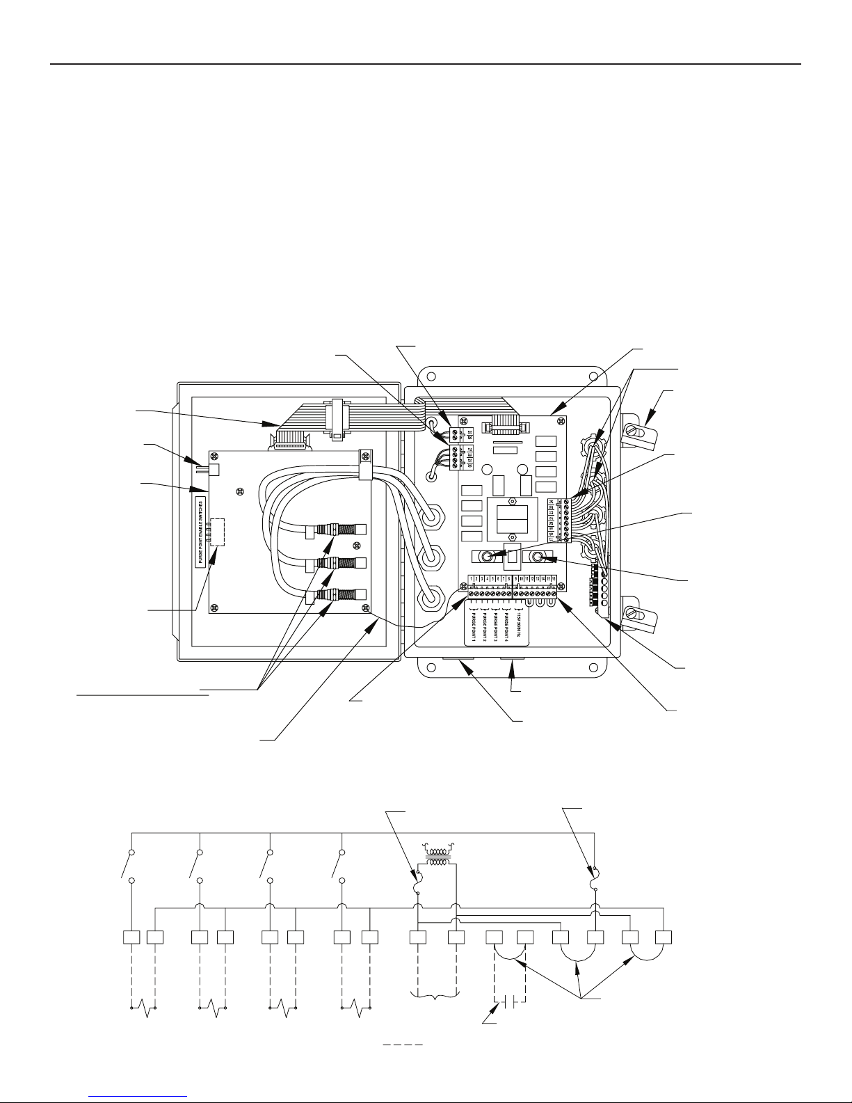
Check: With the temperature sensor plug-in connector
disconnected from power board (see Figure 4), check
the electrical resistance of the sensor across the wire
leads.
Action: If the resistance is not between 30 K ohms and 486
K ohms, replace the temperature sensor (p/n 20-2303).
See also Caution section on page 14.
DIGITAL READOUT FLASHING 4444
PURGED OVER 60 MINUTE TIME LIMIT. If noncondensibles
are released from the purger for 60 minutes continuously, a
time delay will close the purge gas solenoid valve (C). This
limits the possibility of a substantial amount of refrigerant
inadvertently being released into the water bubbler in the
unlikely event of purger malfunction.
REASON 1: A large volume of noncondensibles is
continuously being removed from system.
Action: Reset the time delay by momentarily turning the
APM to Purger Switched Off and back to the desired
operation mode. Delay is now reset for up to another
hour of continuous purging. Otherwise, put the purger
in New System Start-up mode for continuous purging
without the 60 minute time limit.
REASON 2: Purge gas solenoid valve (C) is not opening
or the removable seat/orifice is blocked.
Check: Make sure purge gas solenoid valve (C) is energized.
If not, check for voltage at solenoid coil.
Action: Replace the coil if it is burned-out, otherwise clean
or replace the removable seat/orifice inside the solenoid
valve body. See also the Caution section on page 13.
REASON 3: The shut-off valve located before the purge
gas solenoid valve (C) is closed.
Check: Verify that purge gas is not being sent to the
bubbler.
Action: Open the valve.
SECTION 4 TROUBLE SHOOTING PURGER OPERATION

11 APM-001e
AUG 2015
DIGITAL READOUT FLASHING 5555
PURGER SHUT-OFF REMOTELY. This code indicates
that the optional interlock remote relay contacts are open.
These contacts are connected to the purger via the power/
interlock plug-in connector terminals 11 and 12.
REASON 1: The purger is temporarily shut-off due to the
interlocked compressor (or other device) being shut down
by temperature controls or safety devices.
Check: Wait until the interlocked compressor (or other
device) begins to operate. If digital readout does not stop
flashing diagnostic code 5555, then check the interlock
relay for proper operation.
DIGITAL READOUT FLASHING 6666
LEVEL CONTROL OUT OF RANGE. This Flashing 6666
code will alternate with either a 6661, 6662, or 6663 code.
The second code indicates which level sensor is out of the
normal sensing range. This may indicate a mechanical or
electrical problem with the drainer level sensor (6661), the
low side level sensor (6662), or the high side level sensor
(6663).
REASON 1: One or more level sensors are out of calibration.
Action: Recalibrate the level sensors as follows:
A) First, all refrigerant and oil must be removed from
the APM and the pressure must be zero (atmospheric
pressure)
B) Remove power to purger.
C) install the supplied “jumper” (small white chip) to
the Reset Pins located on the side of the Control
Board, wait 5 minutes. See figure 4. Note: A small
alligator clip can be substituted for “jumper”.
D) Apply power to the APM. The display on the front
of the APM should read “CAL”. With power still
applied, remove “jumper” from the Reset Pins.
E) Recalibration is complete.
REASON 2: Discontinuity in the coaxial wire from the
probe to the control board.
Check: Verify that the level sensor coaxial connectors at
the control board are tight.
Action: If the connections appear proper, replace the
suspected level sensor, with the purger isolated from
the system and pressure at zero. See also the Caution
section on page 14.
DIGITAL READOUT FLASHING 7777
LOSS OF HIGH PRESSURE LIQUID. If the liquid line
solenoid valve remains energized for more than 30 minutes, it
indicates there is insufficient high-pressure liquid available
to maintain an adequate level in the flooded evaporator
of the purger. The purger will not purge air until this is
corrected.
REASON 1: Liquid line solenoid valve (B) is not opening
or the removable seat/orifice is blocked.
Check: Make sure the liquid line solenoid valve (B) is
energized. If not, check for voltage at the solenoid
coil.
Action: Replace the coil if it is burned-out, otherwise clean
or replace the removable seat/orifice inside the solenoid
valve body. See also the Caution section on page 14.
REASON 2: Liquid line restricted.
Check: Look for closed shut-off valves in the liquid line,
plugged strainers, or the plastic shipping cap still in the
liquid line flange.
Action: Inspect piping for a closed shut-off valve. Open
the shut-off valves, clean the strainer, or remove the
shipping cap. See also the Caution section on page 14.
REASON 3: Flooded evaporator is full of oil.
Check: Look for oil at the drain valves.
Action: Drain the oil according to safe refrigeration
practices.
PURGER NOT OPERATING AND THE DIGITAL
READOUT BLANK
REASON 1: One or both of the replaceable 3 amp fuses is
blown. (APM’s shipped before January 1997 have circuit
breakers instead of fuses.)
Check: Check for a blown fuse.
Action: Replace the blown fuse.
REASON 2: Condensation inside the flexible electric
conduit is causing a short in the DIN plug connector.
Note: This only applies to APM purgers shipped before
December 9, 1996.
Check: Remove the DIN plug connector from the solenoid
valve and inspect for moisture or condensation.
Action: Replace the solenoid, flexible conduit, and (if
necessary) the power board. Contact the factory for
an upgrade kit including the solenoid and flexible
conduit. The power board must be ordered separately.
Refer to drawing 2001-80 for power board replacement
procedures.
REASON 3: A short or open on the low voltage side of
the power board.
Check: With power to the APM use a voltmeter to check
for approximately 10V DC across terminals 27 and 30.
Action: If there is no voltage across the terminals, replace
the power board. Refer to drawing 2001-80 for power
board replacement procedures.
REASON 4: One or both solid state fuses (F6A and F6B)
are blown.
Action: Disconnect power and verify continuity across the
fuses. Replace board if no continuity.
SECTION 4 TROUBLE SHOOTING PURGER OPERATION

12
APM-001e
AUG 2015
NONCONDENSIBLES ARE NOT BEING
RELEASED.
(See also page 10; Digital Readout Flashing 3333)
REASON 1: Noncondensibles not present in system.
Check: Compare the refrigerant liquid temperature from
condenser exit with the condensing pressure. The
pressure/temperature relationship should be within 2
or 3 psig (0.14 to 0.21 bar).
Action: None at this time.
REASON 2: Strainer/orifice plugged.
Symptom: The purger appears to be operating properly,
however, the liquid feed line is not frosted.
Check: Look for a restriction in the strainer/orifice.
REASON 3: foul gas line is flooded with liquid.
Symptom: The line from the bottom of the liquid drainer
solenoid valve (A) to the inlet of the purger evaporator
often remains frosted.
Check: Inspect condenser and foul gas piping. In many
cases, the problem is liquid refrigerant being drawn
from the purge point. To prevent this from happening,
select purge point locations above liquid surfaces and
make sure purge point lines are installed so that only
vapor, and not liquid, can be drawn in. Refer to Piping
Instructions in Section I of this bulletin.
Action: Correct condenser and foul gas piping.
REASON 4: High side level sensor not detecting drop in
liquid level due to oil.
Action: Run recalibration procedure per recalibration
instruction on page 11.
AMMONIA INSTEAD OF NONCONDENSIBLES
RELEASED FROM PURGER.
(See also page 10; Digital Readout Flashing 3333)
REASON 1: Purge gas solenoid valve (C) leaking at seat.
Symptom: A slow leak of noncondensibles to the bubbler
when the Purging status light is off.
Check: Look for dirt or a worn seat in the purge gas
solenoid valve (C).
Action: Remove, clean, or replace the seat/orifice and
solenoid tube plunger. See also the Caution section
on page 14.
REASON 2: Oil in purger.
Symptom: No frost around the low side oil drain valve.
Action: Remove oil through both the low side and high
side drain valves (See Figure 1) per safe refrigeration
procedures and suggested oil removal instructions
describe in the Oil Drains section, page 4.
WATER BUBBLER DEVELOPS EXCESSIVE
MINERAL COATING.
REASON 1: Hard water.
Action: Add vinegar to the bubbler water. Then, clean with
the supplied brush. Use a water conditioning housing
and cartridge in the water supply line to the purger.
SECTION 4 TROUBLE SHOOTING PURGER OPERATION

13 APM-001e
AUG 2015
FOUL GAS LINELIQUID LINESUCTION LINE
1/4" NPT
1/4" NPT
¾" SOCKET WELD
½" SOCKET WELD
½" SOCKET WELD (VIEW ROTATED
PIPE THREAD
PIPE THREAD
GAUGE VALVE
GAUGE VALVE
PURGER FRAME
SHUT-OFF VALVE
VPM
FOR CLARITY)
OPTIONAL VALVE PACKAGE FOR AMMONIA SYSTEMS (VPM)
Figure 13

14
APM-001e
AUG 2015
INTRODUCTION
Model APMF AUTO-PURGERs are for use in halocarbon
refrigeration systems. The installation and operation of
these AUTO-PURGERs are similar to that of an ammonia
AUTO-PURGER M.
PIPING HALOCARBON AUTO-PURGERS
The halocarbon liquid line and foul gas line piping and sizing
details are the same as for an ammonia AUTO-PURGER
M. However, the suction line size for halocarbon purgers
should be ¾”(20mm) for suction temperatures down to -20ºF
(-29ºC) to -60ºF (-51ºC) suction temperatures. Condenser
drain lines on halocarbon evaporative condensers must
be trapped and drop vertically 8’ - 12’ (2.5m - 3.7m), or
per manufacturer recommendations. This is to prevent
possible backflow of liquid into one or more condenser
circuits resulting in a flooded purge point.
Purge points are at the same locations as for an ammonia
purger. For evaporative condensers, the purge points are
on the top of the outlet drain line. Although noncondensible
gases are lighter than halocarbon gas, they still collect at,
or near, the outlet.
OPTIONAL VALVE PACKAGE, VPMF
The special construction for APMF AUTO-PURGERs includes
a filter-dryer conditioning system for the foul gas and liquid
line. Water vapor, as well as noncondensible gas, may
be present at each purge point. The filter-dryers remove
this moisture before it can enter the purger. Both dryers
are used to protect the purger internally from freezing
water, but they also supplement water removal of the
primary refrigeration system liquid line dryers. Moisture
indicating sight glasses located downstream of the filter-
dryers indicate when the filter-dryer cores are saturated
with water and must be replaced. Isolation shut-off valves
are included for change out of the filter-dryer cores, and
access valves allow evacuation of the refrigerant from the
filter-dryer shell.
AIR INDICATING COLUMN
While the air indicating column (water bubbler flush system)
is included, the water line and drain line are not required.
Fill the clear tube to the marked line with a lightweight,
clear refrigeration oil. Noncondensibles released from the
purger bubble up through the column, indicating proper
operation.
SECTION 5 APMF AUTO-PURGER M FOR HALOCARBON SYSTEMS
OPTIONAL VALVE PACKAGE FOR HALOCARBON SYSTEMS (VPMF)
Figure 14

15 APM-001e
AUG 2015
PARTS LIST FOR APM (AMMONIA)
ELECTRICAL
Control Board 20-1836
Shield for above 20-2271
Ground Wire for above 20-2270
Power Board 20-1845
3A (amp) fuse (5mm x 20mm) Type F
for Power Board 20-1698
Cable, Control Board 20-1837
Pressure Transducer 20-1857
Temperature Sensor 20-2303
High Side Level Sensor 77-0796
Drainer & Low Side Level Sensor 77-0535
Solenoid Coil Kit, 230V for DIN plug 70-1093
Solenoid Coil Kit, 115V for DIN plug 70-1092
MECHANICAL
Solenoid Tube/Plunger Kit 70-1059
Water Solenoid Valve (D), Less Coil HS2B/1
APM Bubbler 20-1959
Strainer/Orifice Screen Assembly Kit
includes Strainer/Orifice Screen
Assembly and necessary O-Rings
20 -2177
Water Flow Controller 20-1985
Removable Seat/Orifice Kits
For Solenoid Valve (B) or (C) 70-1068
For Solenoid Valve (A) 70-1069
80 psid Check Valve 20-2379
Foul Gas/Liquid Line Strainer Kits
include Strainer Basket and O-Ring 78-1010
PARTS LIST FOR APMF (HALOCARBON)
ELECTRICAL
Control board 20-1836
Shield for above 20-2271
Ground Wire for above 20-2270
Power board 20-1845
3 amp fuse (5mm x 20mm)
Fast-Acting for Power board 20-1698
Cable, control board 20-1837
Pressure transducer 20-1857
Temperature sensor 20-2303
High side level sensor 77-0796
Drainer and low side level sensor 77-0794
Solenoid coil kit, 230V with DIN plug 70-1093
Solenoid coil kit, 115V with DIN plug 70-1092
MECHANICAL
Solenoid tube/plunger kit 70-1059
APMF bubbler 20-2282
Strainer/orifice screen assembly kit
includes strainer/orifice screen assembly
and necessary o-rings
20-2285
Removable seat/orifice kits
For solenoid valve (C) 70-1068
For solenoid valve (A) or (B 70-1069
80 psid check valve 20-1949
Foul gas/liquid line strainer kit
Includes strainer basket and o-ring 78-1010
ORDERING INFORMATION, PURGER
Cat. No. Description
APM Auto-Purger M, 4 points,
for ammonia systems
APMF Auto-Purger M, 4 points,
for halocarbon systems
To Order: Specify catalog number, refrigerant and voltage.
Standard voltage is 115V 50/60Hz;230V 50/60Hz, is available.
CSA and CE mark available.
ORDERING INFORMATION, OPTIONAL VALVE
PACKAGE
Cat. No. Description
VPM Valve Package for ammonia systems
VPMF Valve Package for halocarbon systems
To Order: Specify catalog number and refrigerant. The VPM
optional isolation valve package consists of three flanged
welded assemblies which include the necessary shut-off
valves and gauge valves for the foul gas line, suction line,
and liquid line. The VPMF for halocarbons also includes
filter dryers and moisture indication sight glasses.

16
APM-001e
AUG 2015
400 Quadrangle Dr. Suite F
Bolingbrook, Illinois 60440 USA
Tel: 630.325.1565 Fax: 630.325.1572 Toll: 800.426.7368
USA ∙ Asia ∙ Europe ∙ India ∙ LatinAmerica ∙ MiddleEast
© 2015 Hansen Technologies Corporation
CAUTION
Hansen purgers are for refrigeration systems only. These
instructions and related safety precautions must be read
completely and understood before selecting, using, or
servicing these purgers. Only knowledgeable, trained
refrigeration technicians should install, operate, or
service these purgers. Stated temperature and pressure
limits should not be exceeded. Purger components
should not be removed from the purger unless the system
has been evacuated to zero pressure. See also the Safety
Precautions in the current List Price schedule and the
Safety Precautions Sheet supplied with this product.
Escaping refrigerant can cause injury, especially to
the eyes and lungs.
WARRANTY
Electrical and electronic components are guaranteed
against defective materials and workmanship for 90 days
F.O.B. our plant. All other components are guaranteed
against defective materials or workmanship for one year
F.O.B. our plant. No consequential damages or field
labor is included.
AUTO-PURGER APP
AUTO-PURGER PLUS is a totally automatic, electronically
controlled non-condensible gas (air) and water purger for
reducing the energy costs
of operating an ammonia
refrigeration system.
Shipped preassembled,
prewired, insulated, and
includes an automatic
water bubbler, a relief
valve, and an isolation
service valve package.
One AUTO-PURGER PLUS
is typically sufficient for a
1500 ton (5275 kW) system
(or a 750 ton (2638 kW)
systemoperating below 0
psig (0bar g). All models
suitable for ammonia only.
SELECTING AN AUTO-PURGER®
In addition to the AUTO-PURGER®AP, Hansen
Technologies offers three other versions—the
compact AUTO-PURGER®APM, the gas (air) and
water AUTO-PURGER®APP, and the Nonelectrical
AUTO-PURGER®(NEAP). Use the following
descriptions to help select the best AUTO-PURGER
for your needs. For additional assistance, contact the
factory.
AUTO-PURGER AP
This is the original AUTO-PURGER. It has solid-state
control and is ideal for larger systems, up to 1500 tons
(5300 kW) ammonia. This is two to three times the
air removal capacity of
the Armstrong purger.
With models available to
purge up to 24 points, the
AP features automatic
start-up with electronic
control. The purge cycles
can be individually
adjusted to meet system
requirements. The AP
includes an automatic
water bubbler. An
optional NEMA 4 rated
enclosure is available.
AUTO-PURGER APM
A more compact version of the original AP, the
AUTO-PURGER APM is ideal for medium-size systems,
up to 200 tons (700 kW). Like
the AP, the APM features
automatic start-up with
electronic control. Designed
for up to four purge points, an
electronic “brain” searches
for noncondensible gases
in the system and purges
at those points when air is
present. The APM includes an
automatic water bubbler and
comes standard with a NEMA
12,13 control cabinet. For use
with ammonia refrigeration
systems. Assembled, tested,
and ready to run.
Nonelectrical AUTO-PURGER (NEAP)
The nonelectronical AUTO-
PURGER (NEAP) is ideal for small
systems, up to 100 tons (350
kW). The nonelectronical design
also makes the NEAP ideal for
explosion proof applications.
The simple design of the NEAP
features easy start-up and
is generally used to purge
a single point. For use with
ammonia refrigeration systems.
Assembled, tested, and ready to
run.
Hansen Auto-Purger Specifications
Model
AP
APP
APM
NEAP
Pressure Rating
400 psig
400 psig
400 psig
400 psig
Test Pressure
450 psig
450 psig
450 psig
450 psig
Min. Operating Temp.
-60°F
-60°F
-60°F
-60°F
Max Operating Temp.
240°F
240°F
240°F
240°F
Ammonia Charge
11 lb
14 lb
7 lb
7lb
Cubic Volume
0.5 ft
3
0.7 ft
3
0.3 ft
3
0.2 ft
3
Refr. Capacity (tons)
1 TR
1 TR
0.5 TR
0.5 TR
Certification Type (std)
CRN, CSA
CRN, CSA
CRN, CSA
CRN
HEX Length x Width
(to calculate relief size)
48” x 5”
48” x 5”
18” x 5”
14” x 5”
Bulletin number
AP003
APP001
APM001
NEAP001
This manual suits for next models
2
Table of contents
Other Hansen Auto-purger manuals