manuals.online logo
Brands
  1. Home
  2. •
  3. Brands
  4. •
  5. aci
  6. •
  7. Accessories
  8. •
  9. aci SST2630 Installation instructions

aci SST2630 Installation instructions

Automation Components, Inc.
2305 Pleasant View Road | Middleton, WI 53562
Phone: 1-888-967-5224 | Website: workaci.com
Page 1
Version: 5.0
I0000684
The Probe sensor may be mounted using a 1/4”
mounting clip (ACI Item #108169) on walls or with
cable ties along pipes.
PIPE MOUNTING
For best accuracy and increased thermal conduction
between the pipe and the sensor, ACI recommends to
clean the pipe with an emery cloth or le, before
applying thermal grease. Be sure to insulate the probe
(from the eects of the ambient air) after tightly
fastening to the pipe.
PROBE ASSEMBLY ON PIPE
To x the sensor along a pipe, use cable ties to mount
the sensor probe and wires on the pipe - see Figure 1.
The sensor probe should be mounted under any insulation in direct contact with the pipe using metal pipe
straps. For proper measurement of temperature, thermal conductive compound should be used in
between the sensor probe and the pipe. The installation should be wrapped with insulation to reduce the
eect of ambient air. The plastic housing of the sensor can either be mounted on the pipe with metal pipe
strap or wall mounted.
Locate and record the sensor ID numbers located on a label inside the unit prior to mounting.
The sensor has a Low Battery LED that will start to blink continuously when the battery voltage is low. A low
battery signal is also sent to the receiver for remote indication that the battery should be replaced. If the
battery is not replaced in approximately 2 months, the battery voltage will become so low that the Low
Battery and Data-Link LEDs will not blink. Replace the battery and the Data-Link LED will start blinking
while the sensor is re-establishing communications with the receiver.
Then attach the cover of the sensor by installing the four screws.
REMOTE/STRAP-ON
TEMPERATRE SENSOR SERIES
Installation & Operation Instructions
SST2630
Phone: 1-888-967-5224
Website: workaci.com
GENERAL INFORMATION
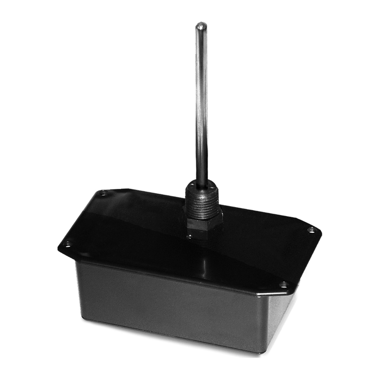
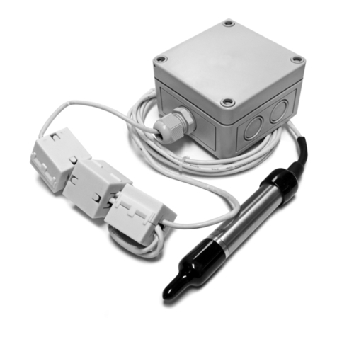
The SST2630 is a battery operated wireless temperature sensor that can be used as a remote probe for monitoring
refrigeration or strap-on for pipes using the reliable 900MHz spread spectrum technology for communication. The
sensing element is in a 2”, 0.25” O.D. stainless steel probe with a 20’ cable length that will be able to cover most duct
applications. The SST2630 is available with a standard or NEMA 4X enclosure. The SST2630 will send the temperature
wirelessly to the RM2432D receiver, which converts the wireless signal to voltage for use with a DDC controller, or to
a transceiver that will send the data to a BAS using BACnet, Modbus, or Lonworks protocol. Transmission distance in
a typical building is 200-300 feet horizontal depending on the layout and construction of the building, and one oor
above and one oor below the transceiver. Sensor distance and reliability can be increased with the addition of a
RR2552B(s) repeater.
Wireless remote/strap-on sensors should be installed within 200 to 300 feet of the receiver. RR2552 signal
repeaters can be installed as needed to increase transmission distance between sensors and receivers.
For optimal temperature measurement, follow these tips:
•Do not install on external walls.
•Avoid air registers, diusers, vents, and windows.
•Eliminate and seal all wall and conduit penetrations. Air migration from wall cavities may alter temperature
readings.
•Do not install near heat sources. eg: lamps, radiators, direct sunlight, copiers, chimney walls, walls
concealing hot-water pipes.
MOUNTING INSTRUCTIONS
PRECAUTIONS
SENSORS, REPEATERS AND RECEIVERS SHOULD NOT BE INSTALLED IN THE FOLLOWING AREAS:
• INSIDE METAL ENCLOSURE / PANEL
• INSIDE OR IMMEDIATELY NEXT TO ELEVATOR SHAFT / ELEVATOR BANKS
• IN FRONT OF OR IMMEDIATELY NEXT TO LARGE TREES OR LARGE BODY OF WATER
TRANSMISSION DISTANCE AND PERFORMANCE WILL BE DRASTICALLY REDUCED.
To select the proper sensor location, rst install and power the receiver. To activate the sensor insert the
battery observing the polarity.
While the sensor is attempting to connect to the receiver the Data-Link LED will blink rapidly 8–10 times
every 10 seconds. Once a connection has been established, the Data-Link LED will blink once to indicate
the data transmission has been received successfully. The Data-Link LED will continue to blink once for
every data transmission. The data transmission rate is programmed into the sensor (normally 1 minute
intervals). To manually initiate a data transmission press the push button switch located by the negative
terminal of the battery.
The Probe sensor may be mounted using a 1/4”
mounting clip (ACI Item #108169) on walls or with
cable ties along pipes.
PIPE MOUNTING
For best accuracy and increased thermal conduction
between the pipe and the sensor, ACI recommends to
clean the pipe with an emery cloth or le, before
applying thermal grease. Be sure to insulate the probe
(from the eects of the ambient air) after tightly
fastening to the pipe.
PROBE ASSEMBLY ON PIPE
To x the sensor along a pipe, use cable ties to mount
the sensor probe and wires on the pipe - see Figure 1.
The sensor probe should be mounted under any insulation in direct contact with the pipe using metal pipe
straps. For proper measurement of temperature, thermal conductive compound should be used in
between the sensor probe and the pipe. The installation should be wrapped with insulation to reduce the
eect of ambient air. The plastic housing of the sensor can either be mounted on the pipe with metal pipe
strap or wall mounted.
Locate and record the sensor ID numbers located on a label inside the unit prior to mounting.
The sensor has a Low Battery LED that will start to blink continuously when the battery voltage is low. A low
battery signal is also sent to the receiver for remote indication that the battery should be replaced. If the
battery is not replaced in approximately 2 months, the battery voltage will become so low that the Low
Battery and Data-Link LEDs will not blink. Replace the battery and the Data-Link LED will start blinking
while the sensor is re-establishing communications with the receiver.
Then attach the cover of the sensor by installing the four screws.
Automation Components, Inc.
2305 Pleasant View Road | Middleton, WI 53562
Phone: 1-888-967-5224 | Website: workaci.com
Page 2
Version: 5.0
I0000684
GENERAL INFORMATION
The SST2630 is a battery operated wireless temperature sensor that can be used as a remote probe for monitoring
refrigeration or strap-on for pipes using the reliable 900MHz spread spectrum technology for communication. The
sensing element is in a 2”, 0.25” O.D. stainless steel probe with a 20’ cable length that will be able to cover most duct
applications. The SST2630 is available with a standard or NEMA 4X enclosure. The SST2630 will send the temperature
wirelessly to the RM2432D receiver, which converts the wireless signal to voltage for use with a DDC controller, or to
a transceiver that will send the data to a BAS using BACnet, Modbus, or Lonworks protocol. Transmission distance in
a typical building is 200-300 feet horizontal depending on the layout and construction of the building, and one oor
above and one oor below the transceiver. Sensor distance and reliability can be increased with the addition of a
RR2552B(s) repeater.
Wireless remote/strap-on sensors should be installed within 200 to 300 feet of the receiver. RR2552 signal
repeaters can be installed as needed to increase transmission distance between sensors and receivers.
For optimal temperature measurement, follow these tips:
•Do not install on external walls.
•Avoid air registers, diusers, vents, and windows.
•Eliminate and seal all wall and conduit penetrations. Air migration from wall cavities may alter temperature
readings.
•Do not install near heat sources. eg: lamps, radiators, direct sunlight, copiers, chimney walls, walls
concealing hot-water pipes.
MOUNTING INSTRUCTIONS
PRECAUTIONS
SENSORS, REPEATERS AND RECEIVERS SHOULD NOT BE INSTALLED IN THE FOLLOWING AREAS:
• INSIDE METAL ENCLOSURE / PANEL
• INSIDE OR IMMEDIATELY NEXT TO ELEVATOR SHAFT / ELEVATOR BANKS
• IN FRONT OF OR IMMEDIATELY NEXT TO LARGE TREES OR LARGE BODY OF WATER
TRANSMISSION DISTANCE AND PERFORMANCE WILL BE DRASTICALLY REDUCED.
To select the proper sensor location, rst install and power the receiver. To activate the sensor insert the
battery observing the polarity.
While the sensor is attempting to connect to the receiver the Data-Link LED will blink rapidly 8–10 times
every 10 seconds. Once a connection has been established, the Data-Link LED will blink once to indicate
the data transmission has been received successfully. The Data-Link LED will continue to blink once for
every data transmission. The data transmission rate is programmed into the sensor (normally 1 minute
intervals). To manually initiate a data transmission press the push button switch located by the negative
terminal of the battery.
FIGURE 1: BULLET PROBE (-BP)
ASSEMBLY
CABLE TIE CABLE TIE PIPE
PIPE
BULLET PROBE
BULLET PROBE
INSULATION ADDEDBARE ASSEMBLY
INSULATION ADDED
TO COVER BULLET PROBE
FIGURE 2: DIMENSIONS
STANDARD
NEMA 4X
1.88"
(47.75 mm)
2.25"
(57.15 mm)
3.20"
(81.28 mm)
5.25" (133.35mm)
5.78" (146.81mm)
Ø 0.19" (4X)
Battery Positive Terminal
Internal Link Button
SST2630A
Heyco Water Tight Fitting
Standard Enclosure
20' CL2P Cable
2.00" x 0.25" Probe
2.56"
(65.024 mm)
4.53"
(115.062 mm)
2.23"
(56.64 mm)
Battery Positive Terminal
Internal Link Button
SST2630AE
Altech Water Tight Fitting
NEMA 4X Enclosure
20' CL2P Cable
2.00" x 0.25" Probe
Automation Components, Inc.
2305 Pleasant View Road | Middleton, WI 53562
Phone: 1-888-967-5224 | Website: workaci.com
Page 3
Version: 5.0
I0000684
WARRANTY
The SST2630 Series are covered by ACI’s Two (2) Year Limited Warranty, which is located in the front of ACI’S
SENSORS & TRANSMITTERS CATALOG or can be found on ACI’s website: www.workaci.com.
W.E.E.E. DIRECTIVE
At the end of their useful life the packaging and product should be disposed of via a suitable recycling
centre. Do not dispose of with household waste. Do not burn.
PRODUCT SPECIFICATIONS
Battery; 1 (Duracell DL123A), Lithium 3V 1400 mAh 45 mA maximum
2-3 years typical
14 to 140ºF (-10 to 60ºC)
5 to 65%, Non-condensing
0 to 176ºF (-17 to 80ºC), 5 to 65% RH, Non-condensing
-40 to 200ºF (-40 to 93ºC)
+/- 1ºF (+/- 0.555ºC) 12 bit resolution
Length: 2” (50.8 mm) | Diameter: 0.25”(6.35mm) | Material: 304 stainless steel
20’ (6.09m) | CL2P plenum rated
Nylon 6/6, Flammability rating UL94V-2
IEEE 802.15.4-2003/2006
900 MHz, Operating Frequency 10 channels between 902 – 928 MHz
Transmitter Power: 11 dBm | Receiver Sensitivity: -11 dBm
75 seconds (default) | 300 seconds (optional)
200 – 300 ft horizontally depending on building type and construction and typically
one oor above and below the transceiver vertically
Standard: ABS Plastic | UL 94 | NEMA 4X: Polycarbonate Plastic | UL94-HB
Input Voltage:
Battery Life:
Operating Temperature Range:
Operating Humidity Range:
Storage Temperature Range:
Sensor Range:
Accuracy:
Probe Dimensions:
Cable Length | Cable Type:
Fitting:
Data Protocol:
RF Characteristics:
Sensor Data Transmission Time:
Transmission Distance:
Enclosure Material | Flammability Rating:
Automation Components, Inc.
2305 Pleasant View Road | Middleton, WI 53562
Phone: 1-888-967-5224 | Website: workaci.com
Page 4
Version: 5.0
I0000684

Other aci Accessories manuals

aci aSENSE RL User manual

aci

aci aSENSE RL User manual

aci A/ASCS User manual

aci

aci A/ASCS User manual

aci TUCH2 User manual

aci

aci TUCH2 User manual

aci A/CTE2 Series Configuration guide

aci

aci A/CTE2 Series Configuration guide

aci OA2630A Service manual

aci

aci OA2630A Service manual

aci HAZARDOUS ROOM Series Installation instructions

aci

aci HAZARDOUS ROOM Series Installation instructions

aci A/CTA2 Series Installation instructions

aci

aci A/CTA2 Series Installation instructions

aci A/CTA2-5 User manual

aci

aci A/CTA2-5 User manual

aci Room Series Installation instructions

aci

aci Room Series Installation instructions

aci A/CTE-50 User manual

aci

aci A/CTE-50 User manual

aci DUCT TEMPERATURE Series Installation instructions

aci

aci DUCT TEMPERATURE Series Installation instructions

aci IMMERSION SERIES Installation instructions

aci

aci IMMERSION SERIES Installation instructions

aci ACCESS series Installation instructions

aci

aci ACCESS series Installation instructions

aci VOC-ROOM Owner's manual

aci

aci VOC-ROOM Owner's manual

aci DUCT Series User manual

aci

aci DUCT Series User manual

aci WPR2-300 Series User manual

aci

aci WPR2-300 Series User manual

aci DT2650 Installation instructions

aci

aci DT2650 Installation instructions

aci TUCH2 User manual

aci

aci TUCH2 User manual

aci ROOM Series Installation instructions

aci

aci ROOM Series Installation instructions

aci BACnet Outside Series Installation instructions

aci

aci BACnet Outside Series Installation instructions

aci HAZARDOUS ROOM Series Installation instructions

aci

aci HAZARDOUS ROOM Series Installation instructions

aci RT2630 Series Installation instructions

aci

aci RT2630 Series Installation instructions

aci A/SCTE-50 User manual

aci

aci A/SCTE-50 User manual

aci A/TT Remote Probe Series Installation instructions

aci

aci A/TT Remote Probe Series Installation instructions

Popular Accessories manuals by other brands

Xiaomi Aqara QBCZ11LM User manual and warranty card

Xiaomi

Xiaomi Aqara QBCZ11LM User manual and warranty card

Chauvet MOT-2 user guide

Chauvet

Chauvet MOT-2 user guide

Philips EasyAir SNS410 MC Design-in guide

Philips

Philips EasyAir SNS410 MC Design-in guide

Siemens milltronics MFA 4P operating instructions

Siemens

Siemens milltronics MFA 4P operating instructions

PCB Piezotronics 352A71 Installation and operating manual

PCB Piezotronics

PCB Piezotronics 352A71 Installation and operating manual

NuTone BK240LWH instructions

NuTone

NuTone BK240LWH instructions

LMI Technologies Dynavision SPR-04 user manual

LMI Technologies

LMI Technologies Dynavision SPR-04 user manual

CS Instruments Vortex VX 570 instruction manual

CS Instruments

CS Instruments Vortex VX 570 instruction manual

PlaneWave Instruments Ascend manual

PlaneWave Instruments

PlaneWave Instruments Ascend manual

Steren TIM-270 instruction manual

Steren

Steren TIM-270 instruction manual

Precision GNAT MX2 quick start guide

Precision

Precision GNAT MX2 quick start guide

Hach ORBISPHERE 31x9 Series Basic user manual

Hach

Hach ORBISPHERE 31x9 Series Basic user manual

Hukseflux FHF04 user manual

Hukseflux

Hukseflux FHF04 user manual

ekwb EK-FC780 GTX Ti INSTALLATION AND MOUNTING MANUAL

ekwb

ekwb EK-FC780 GTX Ti INSTALLATION AND MOUNTING MANUAL

STODDART Woodson Starline Snack Master 10 Series Specification, installation and operation manual

STODDART

STODDART Woodson Starline Snack Master 10 Series Specification, installation and operation manual

nvent Raychem MONI-PT100-4/20MA manual

nvent

nvent Raychem MONI-PT100-4/20MA manual

Behringer U-CONTROL UCA222 user manual

Behringer

Behringer U-CONTROL UCA222 user manual

KSB KSB Leakage Sensor Installation & operating manual

KSB

KSB KSB Leakage Sensor Installation & operating manual

manuals.online logo
manuals.online logoBrands
  • About & Mission
  • Contact us
  • Privacy Policy
  • Terms and Conditions

Copyright 2025 Manuals.Online. All Rights Reserved.