BRACKENHEATH BR1191 User manual
BR1191
Remote 3 Hour Emergency Pack
Remote 3 Hour Emergency Pack
Features
•Plug and play conversion kit for 3 hour maintained emergency
back-up for square and circular LED panels
•Integrated colour changing LED to indicate charging status
•Built in overcharge, over-discharge, and short circuit protection
•Preprogramed for monthly and annual self-testing
•Test button for manual testing
•High temperature Nickel Cadmium batteries
Safety Instructions
1. These instructions should be read carefully and retained after installation for future reference and maintenance.
2. Ensure that the mains power is switched off before carrying out installation or maintenance.
3. It is recommended that installation is carried out by a qualified electrician ensuring the installation complies with the current edition
of IET wiring regulations - BS 7671.
Environmental Instructions
This product may contain substances that can be hazardous to the environment if not disposed of properly. Electrical and electronic
equipment should never be disposed of with general household waste but must be separated for its correct treatment and recovery. Where
possible recycle your packaging.
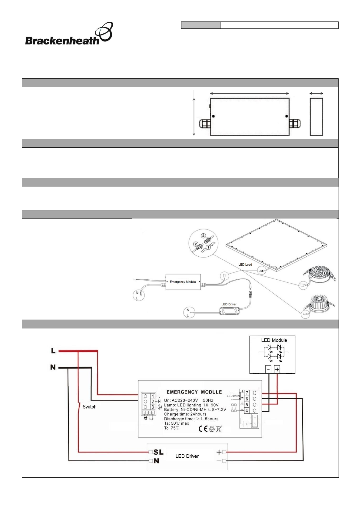
Installation Instructions
•Ensure the mains power is isolated
•Connect LED load and LED driver to the
emergency pack, see diagram on right.
For further wiring details, see typical
conversion wiring diagram section
•Switch on the unswitched supply and
check the charge indicator is on
•Switch on the switched supply and
check the LED Load is illuminating
•Switch off unswitched supply and check
the LED load has switched to emergency
mode with reduced light output
•Switch on the unswitched Supply to
restore LED load to full brightness
Typical Maintained Emergency Wiring Diagram
200mm 33mm
100mm

INS0103 V1.2 11/20 NPD 0653
Deta Electrical Company Limited
UK: Panattoni Park Luton Road Chalton Bedsfordshire LU4 9TT UK
EU: Unit 16 Ashbourne Ind. Est. Ashbourne Co. Meath A84 W972 Ireland
deta.co.uk Technical Helpline: +44(0)1582 544 548
Self-Testing
The emergency pack is preprogramed for periodic monthly and annual self-testing. Once installed, the emergency pack will automatically
run the respective monthly and annual self-test programs.
Self-Test Mode
Emergency Routine
Monthly
During the periodic monthly self-test, the LED load will operate in emergency mode at a reduced light output for
the duration of 2 minutes. After 2 minutes, the LED load will return to normal operation at full brightness.
Annual
During the periodic annual self-test, the LED load will operate in emergency mode at a reduced light output for
the duration of 3 hours. After 3 hours, the LED Load will return to normal operation at full brightness.
Note: If the LED indicator colour turns YELLOW during the annual emergency test, it is possible that:
•Either the battery is not fully charged, or its capacity has depreciated.
•The LED load is not connected
To troubleshoot, check connections between the emergency pack and the LED load.
Manual Testing
During the installation and commissioning of the remote emergency pack, the integrated test button can be used to simulate the periodic
monthly and manual self-testing programs. The emergency pack enters different test modes depending on the duration the test button is
pressed for. Manual testing does not impact or change the auto-testing modes.
Manual Test Mode
Testing Procedure
Monthly
Press and hold the test button for 4-5 seconds and release the test button when the LED indicator colour turns
RED . The emergency pack will now simulate the monthly self-test and the LED Load will operate at reduced
brightness for 2 minutes. To abort the simulation test, press and release the test button and the LED load will
return to normal operation.
Annual
Press and hold the test button for 7-10 seconds and release the test button when the LED indicator colour turns
GREEN. The emergency pack will now simulate the annual self-test and the LED load will operate at reduced
brightness for 3 hours. To abort the simulation test, press and release the test button and the LED load will
return to normal operation.
Note: Manual testing can also be carried out by switching off the unswitched supply with a key-switch.
Routine Test Record
Year 1
Year 2
Year 3
Monthly Test
Date
Sign:
Date
Sign:
Date
Sign:
Functional test
Functional test
Functional test
Functional test
Functional test
Functional test
Functional test
Functional test
Functional test
Functional test
Functional test
Functional test
Three hour test
Specification
Input Voltage:
220-240V 50Hz
Test Switch:
Yes
Output power:
3W
LED Indicators:
Green –Battery fully charged
Emergency Duration:
3 Hours
Red –Battery charging
Battery Charging Time:
24 Hours
Yellow –Battery fault
Emergency Output
Voltage:
12-60V DC
Housing Material:
Steel
Battery Type:
6V 2.5Ah Ni-Cd
Dimensions (LxWxH):
200x100x33mm
Table of contents
Popular Power Pack manuals by other brands


Sealey
Sealey PWRSTART 6000 instruction manual

LEGRAND
LEGRAND Wattstopper BZ-2 Series installation instructions

Philips
Philips SCE4430/05 user manual

APA
APA 16524 manual

Chicago Pneumatic
Chicago Pneumatic PAC E 6 Safety and operating instructions

e-bike vision
e-bike vision PowerPack Series Manual/Safety Notes