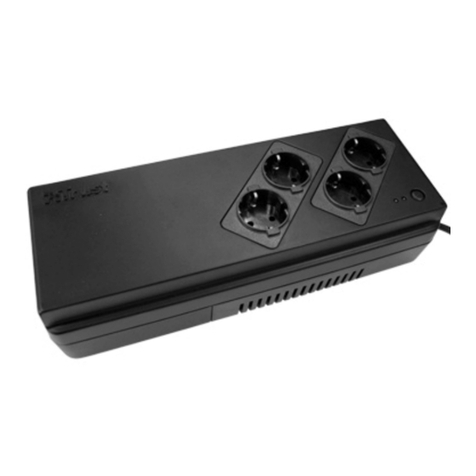
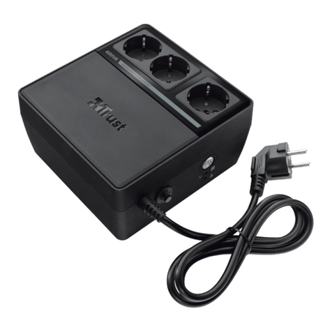
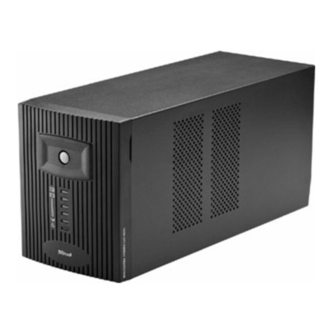
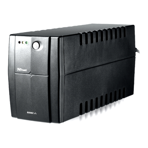
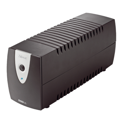
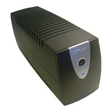
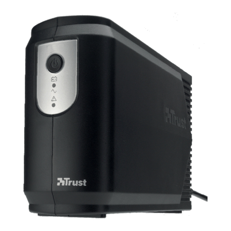
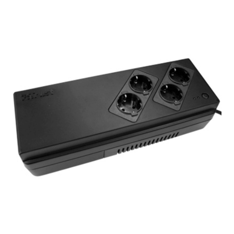
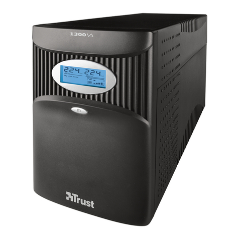
Trust Energy Protector 325 User manual

Trust Energy Protector 325/525
User's Manual

Copyright Statement
No part of this manual may be reproduced or transmitted, in
any form or by any means, electronic or mechanical, including
photocopying, recording, or information storage and retrieval
systems, for any purpose other than the purchaser's personal
use, without the prior written permission of the manufacturer.
Disclaimer Statement
The manufacturer specifically disclaims all warranties, either
express or implied, including but not limited to implied
warranties of merchantability and fitness for a particular
purpose, with respect to the software, the product manual(s)
and written materials, and any other accompanying hardware.
The manufacturer reserves the right to revise or make
improvements to its product at any time and without obligation
to notify any person of such revisions or improvements.
In no event shall the manufacturer be liable for any
consequential or incidental damages, including any loss of
business profits or any other commercial damages, arising out
of the use of its product.
* All company or product names are trademarks or registered
trademarks or service marks of their respective owners.
08640EN.DOC
i
Table of Contents
Introduction-----------------------------------------------------------------ii
Chapter 1: Important Safety Instructions-------------------------1
Chapter 2: System Description--------------------------------------3
Chapter 3: Setup----------------------------------------------------------7
Chapter 4: Operation & Maintenance ------------------------------9
4.1 How to operate the UPS -----------------------------------------9
4.2 How to maintain the UPS --------------------------------------10
Chapter 5: Software (525)-------------------------------------------- 11
Chapter 6: Troubleshooting----------------------------------------- 13
Appendix A: Specifications------------------------------------------ 14
Appendix B: Computer Interface Port --------------------------- 16

ii
Introduction
This manual is a guide to the installation and use of the Trust
Energy Protector 325/525 (UPS).
The Trust Energy Protector provides you with a perfect
protection of your critical devices and makes your PC operate
in an intelligent way. It has been developed with the newest
technology and disposes of a powerful Automatic Voltage
Regulation (AVR) function which allows an input voltage range
from 75% to 125%, including an on-line voltage boost-up and
buck-down.
The Trust Energy Protector is based on microprocessor
controls. This means that it operates as soon as the utility
power is connected, so there is no need to switch it on. In
backup mode, the Energy Protector can be set to turn off
automatically if none of the connected devices is operating in
order to save battery energy.
The Trust Energy Protector is furthermore equipped with
several LEDs to indicate for example when the battery needs to
be replaced and a cyclic self-testing function to verify both the
operation of the UPS and the condition of the battery.

1
Chapter 1:
Important Safety Instructions
Please follow the safety instructions below during the
installation and maintenance of the Trust Energy Protector:
•Unplug the unit and make sure all switches are off before
cleaning.
•Do not attempt to service this product yourself. When the
unit is not functioning, return it to your dealer. Opening or
removing covers may expose you to dangerous voltage.
•The outputs may have high voltage, even if the unit is not
powered on.
•When the fuse has blown, replace it only with a fuse of the
same type to reduce the risk of fire.
•The battery should only be serviced by experienced
personnel. Keep unauthorised personnel away from the
battery.
•Replace the battery only with the same type.
•Do not expose the battery to fire, it may explode.
•Do not open or mutilate the battery. The released electrolyte
is toxic and is harmful to the skin and eyes.
•A battery contains a high short circuit current. Remove
watches, rings or other metal objects and use tools with
insulated handles when servicing the battery.

2

3
Chapter 2:
System Description
Figure 1 Front panel
1. Replace Battery indicator (red LED)
The LED illuminates when the UPS's battery needs to be
replaced.
Note
When replacing the battery, disconnect the power cord before opening
the cover. Be aware of the battery's polarity while installing a new battery
to avoid a short circuit.

4
2. Backup indicator (yellow LED)
The LED illuminates when the UPS is supplying battery
power to the connected devices.
3. Energy Normal indicator (green LED)
The LED illuminates when the input voltage is normal. In
case of power failure or automatic shut down to save
energy, this LED will flash every 2 seconds.
4. On/Off/Test/Silence button
Press the button and hold it longer than 1 second to switch
the UPS on and off. Press the button less than 1 second to
activate the self test or silence the backup alarm.
5. Backup mode (slow alarm)
In this mode, the yellow LED illuminates and the UPS
sounds an audible alarm. The alarm stops when the UPS
returns to its normal operation.
6. Low Battery (rapid alarm)
This mode means that the battery energy runs low. The
UPS is beeping rapidly. The alarm stops when the UPS
shuts itself down or returns to its normal operation.
7. Overload (continuous alarm)
The UPS is overloaded when the connected devices exceed
the maximum capacity and will then emit a continuous
alarm. Remove non-critical devices from the UPS to stop
the overload.
8. Name plate

5
Figure 2 Rear panel
1. Computer Interface (525)
The interface provides a RS-232 serial connection and a
relay signal to support Novell, Unix, Windows, DOS and
other operation systems.
2. Power output
3. Power input

6

7
Chapter 3:
Setup
Figure 3 Connections
# 1 connects the UPS to the mains.
# 2 connects the UPS to your PC for power supply.
# 3 connects the UPS to the serial input of your PC to allow
you to view the status of the UPS with special software (525).
1. Placement
Install the UPS in a protected area with adequate air flow
and free of excessive dust. Do not put the UPS in an area
with extreme temperatures or humidity.
2. Connecting Computer Interface (Optional)
UPSMON or other power management software and
interface kits can be used with this UPS. Use only kits
supplied or approved by the manufacturer.
Connect the interface cable to the 9 pin interface port on the
rear panel of the UPS, if you want to use this option (see
figure 3: # 3).

8
Note
The computer interface connection is optional. The UPS also functions
without an interface connection.
3. Connecting to mains
Use the supplied AC power cord to connect the UPS to the
mains to power up the UPS (see figure 3: # 1).
4. Charging the battery
The UPS charges its battery whenever it is connected to the
mains. For best results, charge the battery for 4 hours when
you use the UPS for the first time.
5. Connecting devices
Use the supplied IEC cord to connect devices with the UPS
(see figure 3: # 2).
Plug the devices into the output connectors on the rear
panel of the UPS. If you want to use the UPS as a master
on/off switch, make sure that all the connected devices are
switched on.

9
Chapter 4:
Operation & Maintenance
4.1 How to operate the UPS
1. Switch on
Press and hold the on/off/test/silence button for more than 1
second until the Energy Normal LED is lit. The UPS will
perform a self-test each time it is switched on.
2. Switch off
Press and hold the on/off/test/silence button for more than 1
second until the Energy Normal or Backup LED goes out.
3. Self-Test
Use the self-test function to verify both the operation of the
UPS and the condition of the battery. When the UPS is
switched on, press the on/off/test/silence button for less
than 1 second. The UPS will immediately start the self-test.
During the self-test, the UPS operates in the Backup mode
and will go back to the Energy Normal mode as soon as the
self-test is finished.
4. Silence
Use this function to silence the alarm. When the UPS is in
the Backup mode, press the on/off/test/silence button for
less than 1 second.
Note
This function does not work when the UPS has a Low Battery or Overload
status.
If you are using the UPSMON software, you can set the UPS to turn off
automatically during the Backup mode, if none of the connected devices
is operating.

10
4.2 How to maintain the UPS
The unit is designed for years of trouble-free operation, so only
a little maintenance is required. Please pay attention to a few
helpful instructions:
•Make sure the UPS is off before you attempt to clean it.
•Do not use liquid or aerosol cleaners, use only a water
dampened cloth to wipe the exterior occasionally.
•Periodically vacuum dust from ventilation openings.

11
Chapter 5:
Software (525)
If you have connected the UPS to a remote port (COM 1 or
COM 2) of your PC, you can use the supplied program
UPSMON. Please refer to the READ.ME file for installation
instructions and available features.
UPSMON displays all the diagnostic symptoms on your
monitor, such as voltage, frequency, battery level etc. It is also
possible to shut down a connected device in the event of power
failure.
The software is available for DOS and Windows 3.1x or
Windows 95.
Figure 4 UPSMON for DOS

12
Figure 5 UPSMON for Windows

13
Chapter 6:
Troubleshooting
If the UPS does not function properly, please check the
troubleshooting chart below. When the unit has to be returned
to the dealer for service, write down the information below:
- Model number and serial number
- Date of purchase
- Full description of the problem
Finally, pack the UPS in the original carton.
Troubleshooting Chart
Problem Possible Cause Action
UPS is not switched
on
LED is not lit
1 on/off/test/silence
button not pressed or
pressed too short
2 battery voltage less
than 10V
3 PCB failure
4 load less than 15W
in battery mode
1 press the on/off/
test/silence button for
more than 1 sec.
2 recharge the UPS
for at least 4 hours
3 PCB needs to be
replaced, call for
service
4 normal condition
UPS is always in
battery mode 1 power cord is loose
2 AC fuse has burned
out
3 line voltage is too
high, too low or has
blacked out
4 PCB failure
1 reconnect it
2 replace the AC fuse
3 normal condition
4 PCB needs to be
replaced, call for
service
Back-up time is too
short 1 battery is not fully
charged
2 PCB failure
1 recharge the UPS
for at least 4 hours
2 PCB needs to be
replaced, call for
service
Buzzer is
continuously beeping 1 overload 1 remove the non
critical devices
Red LED is lit battery failure recharge the UPS for
at least 4 hours, if the
problem is not solved,
replace the battery,
call for service

14
Appendix A:
Specifications
Model 325
(UPS+AVR) 525
(UPS+AVR)
Power rating (UPS output) 325 VA 525 VA
Input voltage
frequency
75% to 125% of 100V, 110V,
120V, 220V, 230V, 240V
50Hz or 60Hz
Output
(inverter) voltage
voltage regulation
frequency stability
wave form
115V, 230V
± 3%
1000 PPM
PWM step wave
Back-up time 10 to 30 min. (depending on
computer load)
Transfer line to inverter
inverter to line
transfer time
over-voltage transfer at 125%
nominal
under-voltage transfer at 75%
nominal
over-voltage re-transfer at 121%
nominal
under-voltage re-transfer at 79%
nominal
0.3 ms inverter to line; 2 ms line
to inverter
AVR
(on-line mode) on-line boost-up
on-line buck-down
AVR automatically increases
output voltage 15% above input
voltage if -9% to -25% of nominal
AVR automatically decreases
output voltage -15% below input
voltage if +9% to +25% of
nominal
Protection unit input
UPS output
overload
UPS output short
circuit
fuse for overload protection
electronic type protection
complete UPS shutdown
immediately if overload exceeds
130%
UPS output cut off immediately
Indicator on-line, battery backup, replace
battery

15
Alarm battery backup
battery low
overload
slow beeping sound (about 0.47
Hz)
rapid beeping sound (about
1.825 Hz)
continuous beeping sound
Filter EMI/RFI filter 10 dB at 0.15 Mhz,
50 dB at 30 MHz
Spike
protection 110/120V model
220/240V model
max. energy: 320 Joules/2 ms;
clamping voltage: 360/50A
max. energy: 320 Joules/2 ms;
clamping voltage: 765/50A
Interface D type 9 pin
connector provides both RS-232 and
contact signal and many
functions such as power failure,
battery low, UPS shutdown,
power failure history record,
schedule on/off, countdown time
setting, UPS power status
display, back-up time prediction
(not available for 325).
Physical dimension in mm
(W x D x H)
net weight
gross weight
97x260x135
4.7 kgs
5.0 kgs
97x320x135
6.2 kgs
6.5 kgs
Note
Characteristics are subject to change without prior notice.

16
Appendix B:
Computer Interface Port (525)
D type 9 pin connector
Provides both RS-232 and relay signal. UPS can send power
failure and battery low signals to the PC and receive shutdown
signal and scheduled on/off time table from the PC.
Figure 6 D type 9 pin connector
1. contacts normally open
2. signal high minimal 1 second
3. low battery
4. mains failure
5. ground
6. UPS shutdown or RS-232 TD pin 3
7. RS-232 RD pin 2
8. RS-232 RTS pin 7
9. RS-232 DTR pin 4
10. no connection
11. pin number
This manual suits for next models
1
Table of contents
Other Trust UPS manuals

Trust
Trust 14948 User manual

Trust
Trust 17238 User manual

Trust
Trust 14948 User manual

Trust
Trust Wireless Tablet Series User manual

Trust
Trust PW-5060S 600VA UPS User manual

Trust
Trust PW-4130M 1300VA MNGT UPS User manual

Trust
Trust UPS 1000 VA User manual

Trust
Trust PW-4055T User manual

Trust
Trust 400 User manual

Trust
Trust 17938 User manual
Popular UPS manuals by other brands

Mitsubishi Electric
Mitsubishi Electric Netcom 2 user manual

Atlantis Land
Atlantis Land OnePower A03-S801 Technical features

Eaton
Eaton Powerware 9140 user guide

Eaton
Eaton Powerware 9910-E64 Handbook

MGE UPS Systems
MGE UPS Systems Pulsar ellipse 1200 Installation and user manual

Eaton
Eaton 3S700D Installation and user manual