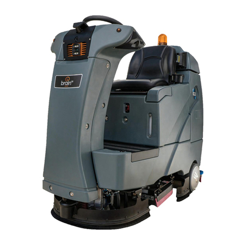
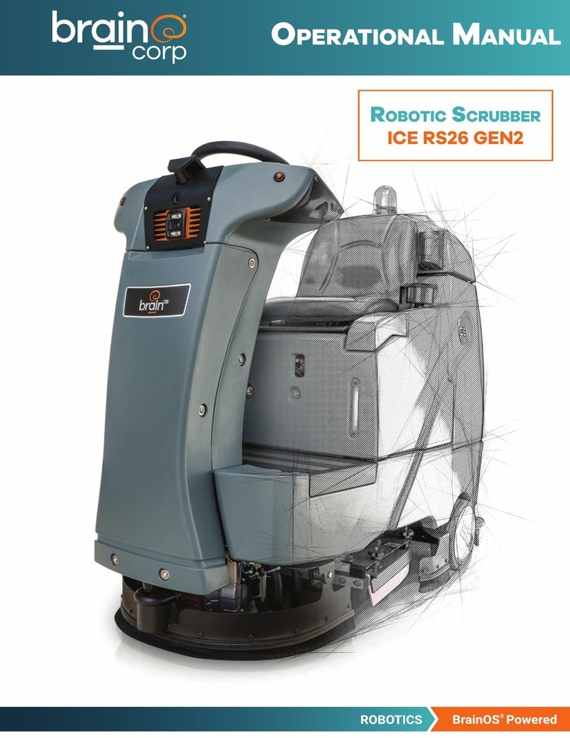
Brain Corp Minuteman User manual

Steering Troubleshooting Guide
Date Published: 4/9/21
©2020 Brain Corporation. All rights reserved.
Steering
Troubleshooting
Guide for OEM

Steering Troubleshooting Guide
Date Published: 4/9/21
Brain Corporation Proprietary and Confidential Page 2of 64
This document contains information confidential and proprietary to Brain Corporation. It may not be
transmitted, modified, duplicated, disclosed, or distributed without prior written permission of Brain
Corporation. This document may only be viewed by third parties under an active non-disclosure
agreement (NDA) with Brain Corporation covering the scope of the information herein. If you received
or obtained this document outside of these requirements, please destroy all copies and report this error
to legal@braincorp.com.
©2020 Brain Corporation. All rights reserved.
Brain Corporation
Corporate Headquarters Contact Information
10182 Telesis Court Suite +1-619-738-4675, 5 am –5pm PST

Steering Troubleshooting Guide
Date Published: 4/9/21
Brain Corporation Proprietary and Confidential Page 3of 64
Table of Contents
Revision History 5
Definitions, Acronyms, and Abbreviations 5
Overview 6
When To Use It 6
For more information on the error codes please refer to the OEM Error Code Reference Document
Brain Internal Assist Codes
https://braincorporation.atlassian.net/wiki/spaces/TS/pages/298582085/Error+Codes+and+Error+Inv
entory OEM Assist Code Doc The latest OEM error code document is located in the Zendesk
Guide webpage 6
How To Use It 6
Required Tool List 7
OEM Diagnostics 8
Assists 8
U-Joint 8
Traction Encoder failed or failing 9
Wheel Slip 10
Loose Steering Encoder 11
Steering Encoder Malfunction 11
Example of an assist with customer driving 12
Tech Diagnostics 13
Hardware Inspection 13
U-Joint Check 13
Steering Motor Check 14
Steering Encoder Check15
Steering Amplifier Check17
Traction Encoder Check 18
Voltage / Continuity Testing/Swap 20
UI based diagnostics (OS version 3.1.x +) 23
Sensor History 25
Steering Service Tests 26
Calibration 26
Appendix A - Tech Steering Checklist 29

Steering Troubleshooting Guide
Date Published: 4/9/21
Brain Corporation Proprietary and Confidential Page 4of 64
Appendix B - Tech Solution Codes 30
CALIBRATION-01 31
UJOINT-01 31
STENCODER-01 32
STENCODER-02 32
MOTOR-01 33
AMP-01 33
AMP-02 34
DOWNTRUNK-01 34
ANGLE-01 35
BCM-01 35
TRACTION-01 36
Appendix C - How to replace the Traction Encoder 36
Appendix D - How to Replace the Steering Motor 38
Appendix E –U-Joint Replacement 45
Appendix F –Steering Amplifier (MAM) replacement 51
Appendix G –Steering Encoder replacement 52
Appendix H –Down Trunk Cable replacement 60

Steering Troubleshooting Guide
Date Published: 4/9/21
Brain Corporation Proprietary and Confidential Page 5of 64
Revision History
Revision
Date
Description
Draft
4/9/2021
Submitted for Peer Review
01
Initial Release
Definitions, Acronyms, and Abbreviations
Term
Definition
BCM
Brain Control Module
DMM
Digital Multimeter
MAM
Motor Amplification Module
Down Trunk
Cable harness that goes from the down port on the BCM
OEM
Original Equipment Manufacturer
Examples of commands
Caution, this might cause serious system problems. Stop and ensure
you understand what is being asked.

Steering Troubleshooting Guide
Date Published: 4/9/21
Brain Corporation Proprietary and Confidential Page 6of 64
Overview
This guide provides information on how to troubleshoot steering related issues for any
autonomous floor scrubbers powered by BrainOS. In order to effectively troubleshoot any
issue, please review this troubleshooting guide in the order given to determine the proper
resolution.
When To Use It
Please proceed with this document if you encounter any of the codes below:
Assist
100, 101, 102, 218, 224, 40002, 40004, 40006, 60400, 60461
Errors
501,502, 504, 20003, 20009, 40007
Startup
5010
For more information on the error codes please refer to the OEM Error Code
Reference Document
Brain Internal Assist Codes
https://braincorporation.atlassian.net/wiki/spaces/TS/pages/298582085/Error+Codes+and+Err
or+Inventory
OEM Assist Code Doc
The latest OEM error code document is located in the Zendesk Guide webpage
How To Use It
The Steering Troubleshooting Guide walks you through several important steps in
troubleshooting an Autonomous Scrubber:
1. Part 1: Check Emerging Issues
2. Part 2: ROC Portal
3. Part 3: Connectivity Testing
4. Part 4: Onsite Tech troubleshooting
Complete the steps in the order they are listed!

Steering Troubleshooting Guide
Date Published: 4/9/21
Brain Corporation Proprietary and Confidential Page 7of 64
The following steps are intended to be performed in the exact order listed in this
document. It is essential to collect pictures and take notes throughout the process.
Required Tool List
The following is the list of tools needed to service the Steering? related issues for any
autonomous floor scrubbers powered by BrainOS.
Item
Image Details
Hex Drivers
●2 mm
●2.5 mm
●3 mm
7 mm socket wrench
Digital Multimeter (DMM,
Fluke 101 Model or
equivalent)
Fine Test Leads (Model MICTL-
013 or equivalent) or back
probes.
Cable Tie Cutter
Probing Adaptors (Optional)
https://www.amazon.com/E
DGELEC-Breadboard-
Optional-Assorted-
Multicolored/dp/B07GD2BW
PY

Steering Troubleshooting Guide
Date Published: 4/9/21
Brain Corporation Proprietary and Confidential Page 8of 64
OEM Diagnostics
When replacing any steering component, tech must perform a steering calibration.
****Print and update the checklist!****
To assist with troubleshooting, there is a troubleshooting checklist in Appendix A. This
checklist needs to be printed, filled out, and submitted along with the pictures and
notes.
Assists
Below are some example assists that you might run into when having Steering issues. Go
to the ROC Portal and review the assists for that specific machine. When reviewing each
assist it is really important to look at the images and assist replay to see what triggered
this assist to happen. By reviewing assists it allows us to get a better understanding of
what type of issues the machine could be having. For the latest list of assist codes please
reference the most updated error code document. Make sure to watch the playback as
it gives a better understanding of what you are looking at in the static maps.
U-Joint
These assists do not necessarily show that a U-joint if broken. It could be as simple as
the set screws or bad calibration.
●The below assist when played shows that the scrubber is always to the right of the
trained path. The Scrubber constantly tries to turn left slightly to come back on path.

Steering Troubleshooting Guide
Date Published: 4/9/21
Brain Corporation Proprietary and Confidential Page 9of 64
Tennant Link: None
Traction Encoder failed or failing
When viewing these assists you will notice that the scrubber sits still while the
environment is moving. This will indicate that the traction encoder or cable has
failed.
●Failing Traction encoder
This shows the traction encoder working then at the end of the video the
traction encoder stops working. This indicates that the Traction Encoder or cable
has failed.

Steering Troubleshooting Guide
Date Published: 4/9/21
Brain Corporation Proprietary and Confidential Page 10 of
64
●Tennant Link:
https://tennant.prod.roc.braincorp.com/assists/3S5ERDYHVSHP7
H6C3WD48TPVVT
●Failed Traction Encoder
This shows the machine from the start of the assist sitting still and the objects
are moving in relation to the Robot. This indicates that the Traction Encoder or
cable has failed.
●Tennant Link:
https://tennant.prod.roc.braincorp.com/assists/2VPKCPXWRBMB
FCK11KNKMJ9SXC
https://tennant.prod.roc.braincorp.com/assists/4WAKMQ30AMXX02WB
C9QY2J4M9F
Wheel Slip
In the below assists we have an example of Wheel Slip. You can see places
where the Robot thinks it has moved but the shelving moves and stays ahead of
the scrubber. We have seen worn pads and broken scrub deck springs cause this
issue. This does cause de-localization
●Tennant Link:
https://tennant.prod.roc.braincorp.com/assists/2E4E9XT7WPSPNTXE8TP
2WR3BYG
https://tennant.prod.roc.braincorp.com/assists/08B8R52AW0M1FWWY5TDAM9
AFA6

Steering Troubleshooting Guide
Date Published: 4/9/21
Brain Corporation Proprietary and Confidential Page 11 of
64
Loose Steering Encoder
Steering encoder is mounted incorrectly or has set screws loose. Costmap shows
an adjusted corrective route compared to straight planned route after turns are
not registered entirely or properly
●Tennant Link: None
Steering Encoder Malfunction
The adjusted route (blue line) shows no suggestions (remains straight) while the
planned route(green line) becomes more mismatched in relation to the body of
the scrubber. Encoder is not registering turns.

Steering Troubleshooting Guide
Date Published: 4/9/21
Brain Corporation Proprietary and Confidential Page 12 of
64
●Tennant Link:
https://tennant.prod.roc.braincorp.com/assists/1F9GQZ7QYP1K4
VYF71MZDQ86JB
Example of an assist with customer driving
This example shows the customer driving the scrubber. You can tell this because
there are not any red arrows nor pathing lines.
Tennant Link: None

Steering Troubleshooting Guide
Date Published: 4/9/21
Brain Corporation Proprietary and Confidential Page 13 of
64
Tech Diagnostics
Please use the Tech Steering checklist in Appendix A. Submitting this checklist is required.
Hardware Inspection
U-Joint Check
1. Remove the access panel to access the steering column.
Figure 0: Access Panel
NOTE: When inspecting the U-joint, ensure that the pin is not missing
Take multiple pictures of the steering U-joint that shows the pins on all sides.
2. Inspect the U-joint for damage, set screws being loose or lost, and other damage.
See the pictures below for a reference.
Example of a U-joint in good condition

Steering Troubleshooting Guide
Date Published: 4/9/21
Brain Corporation Proprietary and Confidential Page 14 of
64
Example of a broken U-joint
3. Look for slop in the U-joint itself. It may look good, but may be really loose or otherwise
worn.
4. Verify that ALL of the set screws are present - there are a total of four on ICE and two on
Minuteman. The keys within the U-joint also have to be present and in the proper
location.
5. If U-joint is broken, worn out or missing a pin, refer to UJoint-01
Steering Motor Check
1. Remove both the front and back access panels.
Removing both access
panels
2. Ensure that the steering motor cable and power connector are not loose or damaged.
3. Ensure the presence of the ferrite and it is snapped closed and that it is not broken.
4. Ensure that the steering motor is not leaking oil.

Steering Troubleshooting Guide
Date Published: 4/9/21
Brain Corporation Proprietary and Confidential Page 15 of
64
5. Take pictures of the steering motor from both front and back, along with the steering
connection to the motor amp and power.
6. See the pictures below for a reference.
Steering motor –back and front view
7. Steering motor common issues:
a. If the steering motor is leaking oil, refer to solution code MOTOR-01
b. If the steering motor cable is damaged, refer to solution code MOTOR-01.
Steering Encoder Check
1. Inspect the steering encoder and the associated wiring for physical issues.
2. Turn the steering wheel left and right to inspect that all set screws are installed and
properly tightened.
3. Unscrew the cable for the steering encoder connected to the right cylinder, inspect the
pins, and then screw it tightly back in place.

Steering Troubleshooting Guide
Date Published: 4/9/21
Brain Corporation Proprietary and Confidential Page 16 of
64
4. Inspect the steering encoder and ensure that it is properly mounted.
Steering encoder in good condition/properly mounted
NOTE: Ensure that the steering encoder cable is not loose, and the steering encoder is
mounted like the picture above.
NOTE: The steering encoder pictured above is rotated. Encoder may or may not be broken.
5. Take pictures of the steering encoder that show the overall condition, condition of
the wires, and the set screws.
6. Steering Encoder common issues
a. If the steering encoder is missing set screws, not mounted properly, or is
damaged, refer to solution code STENCODER-01.

Steering Troubleshooting Guide
Date Published: 4/9/21
Brain Corporation Proprietary and Confidential Page 17 of
64
b. If the wiring to the steering encoder is damaged, refer to solution code
Downtrunk-01
Steering Amplifier Check
1. Remove the front cover from the machine to check the steering motor amplifier module
(MAM).
2. Inspect the steering amplifier and wires for damage.
3. Unplug the connectors, inspect the pins for damage, and plug them back in. Ensure the
connectors lock into place.
4. Take pictures of the steering amplifier and condition of the cables and pins.
5. Examples
a. Example of a Good steering amplifier
b. Example of a Bad Steering amp (Damaged wiring)
6. Steering Amplifier common issue

Steering Troubleshooting Guide
Date Published: 4/9/21
Brain Corporation Proprietary and Confidential Page 18 of
64
a. If the wheel is hard to turn, unplug the steering amplifier connection. If the
steering is easier, then it is usually a bad steering amplifier. Refer to solution
code AMP-01.
b. If there is a damaged left male connector that has missing pins, a broken
connector housing or a broken retention clip, refer to solution code AMP-01.
c. If there is a damaged left female connector that has any damaged wires, a
broken connector housing a broken retention clip or something stuck in the
connector, refer to solution code AMP-02.
d. If there is a damaged right male connector that has missing pins, refer to solution
code AMP-01.
e. If there is a damaged left female connector that has any damaged wires or
something stuck in the connector, refer to solution code Downtrunk-01.
Traction Encoder Check
The Traction Encoder is responsible for tracking the movement (distance) traveled by the
scrubber. As the traction wheel spins, the encoder counts ticks and relays that information to
the BCM, thereby quantifying and monitoring how much distance the scrubber has moved. The
purpose of this check is to ensure the traction encoder is not damaged.
1. Ensure that the hex screw (indicated with the red arrow in the Figure below) is tight. It
should enable the encoder to be clamped to the axel. As the unit is driven, the axel
(indicated with the yellow arrow in the Figure below) should spin.

Steering Troubleshooting Guide
Date Published: 4/9/21
Brain Corporation Proprietary and Confidential Page 19 of
64
2. Inspect the traction encoder cabling for damage (cut or torn).
3. Take pictures of the traction encoder and condition of the cables
4. Traction Encoder Common Issues
a. If the traction cabling is damaged, the traction encoder will need to be replaced.
Refer to solution code TRACTION-01
b. If the traction encoder itself is physically damaged then the traction encoder will
need to be replaced. Refer to solution code TRACTION-01

Steering Troubleshooting Guide
Date Published: 4/9/21
Brain Corporation Proprietary and Confidential Page 20 of
64
Voltage / Continuity Testing/Swap
●If you suspect wiring use the Chart below to check voltage and continuity
If continuity testing fails please Use Solution Code Downtrunk-01
Down Trunk BCM connector - Notice Pin Numbering
Traction Encoder connector- Notice Pin Numbering
Table of contents
Other Brain Corp Scrubber manuals
Popular Scrubber manuals by other brands
Stratasys
Stratasys ProAero+ Installation and user manual

IPC
IPC CT70 Series quick guide
Tacony
Tacony Powr-Flite BLACK MAX PFX1350 Series Operators manual and parts lists
Lamona
Lamona LAM2601 Instructions and installation
Fimap
Fimap MINNY 20 Use and maintenance
Hover Scrubber
Hover Scrubber +PLUS instructions
