BrandMotion ADAS-1000 User manual


Verified ADAS Functions Which Were Adopted By Auto Makers As OEM
Intelligent Lane Departure Warning Via Vehicle’s Turn Signal Connection!
Front Collision Warning Even At Low Speed !
Easy But Professional Installation Mode !
Full HD Crystal Clear Image Quality !
Overheating Prevention Power System !
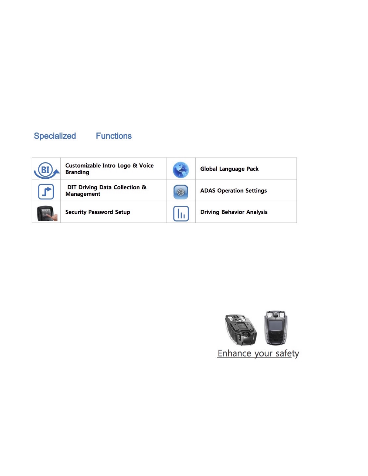
Specialized B2B Fleet Management Tools !
Main Features of ADAS CAM

[Main Body & Functions]
Front
Camera
(Full HD)
Internal GPS
Security
LED
Volume
Adjustment
Button
Menu
Button
Touch
LCD
Manaul
Recording
Button (REC)
Camera
Angle
Adjuster
MIC
DC power port
(3.5 pi)
Micro SD card
socket
Power Supply
Connection
Extra Secondary Camera
Connection

1 Clean installation
surface of windscreen
(windshield)
6 If powered on , follow
the installation guide to
start setup.
2 Remove tape off
bracket and install in
suitable place
horizontally
7 When setup gets
completed , Live-view
screen will appear .
3 After attaching mini
HUB , connect and
arrange the main body-
to-mini HUB cable .
* Installation Notice2.
! Turn off vehicle power completely before
①connecting product to mini HUB
②and connect optional devices( display & vibrator )
to mini HUB
③ at the finish , connect the vehicle cable
! If the product and optional devices are connected
when turned-on vehicle power is applied to mini HUB ,
it may cause internal product damages.
! It is recommended to change settings when vehicle
power is switched to IG status. If Camera Reset is
done in the unstable shaking condition , ADAS
functions may not perform well enough.
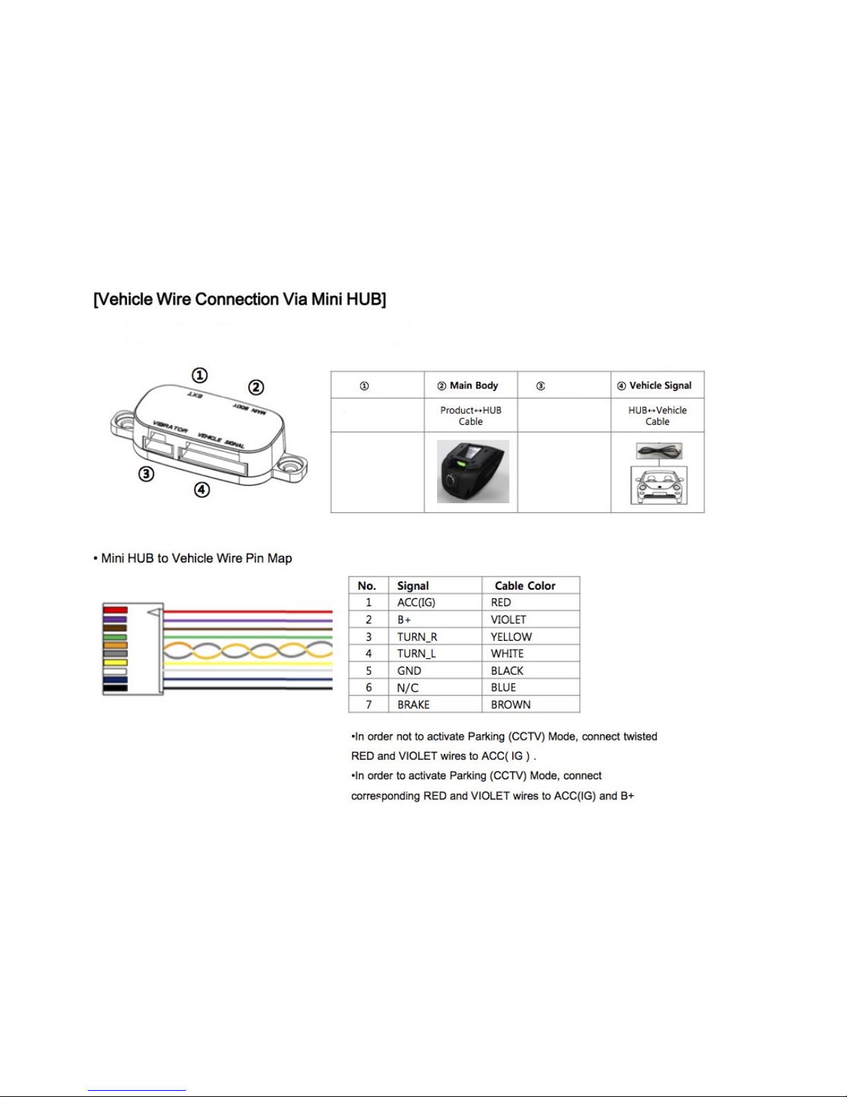
4 Connect power cable to
arranged vehicle wires
(refer to mini Hub Pin
Map)
5 Connect optional
devices firstly to mini
hub, afterwards ,
connect the vehicle
cable
[ Basic Installation Guide ]
This instruction shows how to install the main body and basic components .Please read carefully before
installation.
[Installation Mode]
* Install Mode is to support easy setup for proper ADAS performance .
* Install Mode appears when booting up for the first time. After Installation gets finished , it will not appear again.
* If setup values are inputted differently via menu screen or manager program , the latest input values will be applied .
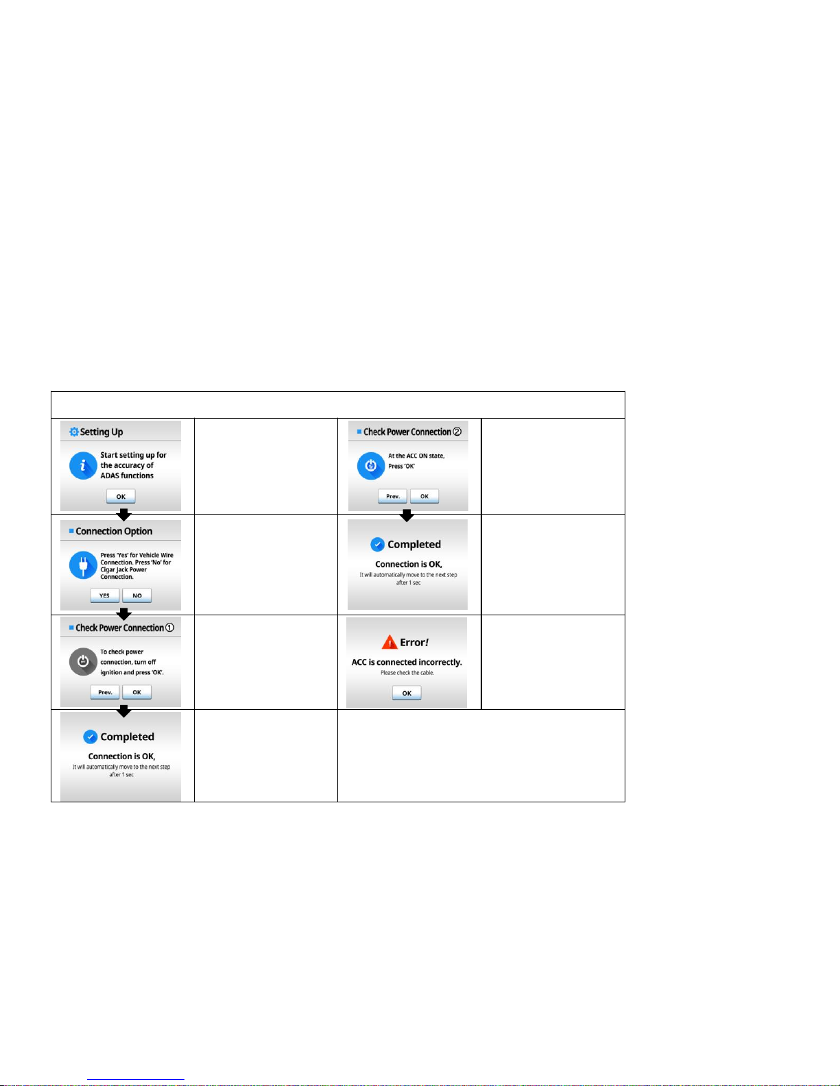
* Check Power Connection
It is the starting screen
of Install Mode .
Press the OK button
②Check whether power
is connected properly
Switch to ACC On
status , and press OK
Choose the desired
connection method,
Vehicle Power & wire
Connection- Press OK
Simple Cigar Jack
Connection – Press No
This notice screen will
appear if the connection
is correct.
①Check whether power
is properly connected ,
Turn off engine
completely and press
OK
Error message will
appear if connection is
incorrect.
Start installation from
the beginning after the
product turns off
This notice screen will
appear if the connection
is correct.
* ‘Press Prev. button to return to previous screen .

* Check Indicator Lights
Check turn signal wire
connection,
Turn off indicating lights
and press OK
<NO>
If both Left & Right
arrows are turned on ,
Press YES.
If only 1 arrow is
turned on , Press NO.
If both lights are off
– Press Yes
If one light or both lights
are on
– Press No
<YES>
Turn on Left indicator
light , and check if the
left arrow in the display
is On .
Press YES if the left
arrow light turns on
<YES>
The vehicle signal is
incompatible with
product signal.
Change the signal by
changing High/Low,
LOW→HIGH // HIGH→LOW
<NO>
* If only 1 arrow is on,
check the cable
connection again .
* If both arrows are off ,
return to the turn signal
check screen②.
<YES>
Turn on Right indicator
light , and check if the
right arrow in the display
is On.
Press YES if the right
arrow light turns on
<NO>
Turn signal connection
is incorrect, check the
cable connection again.
Restart the procedure
after product turns off
<YES>
This Notice screen will
appear if the connection
is correct.
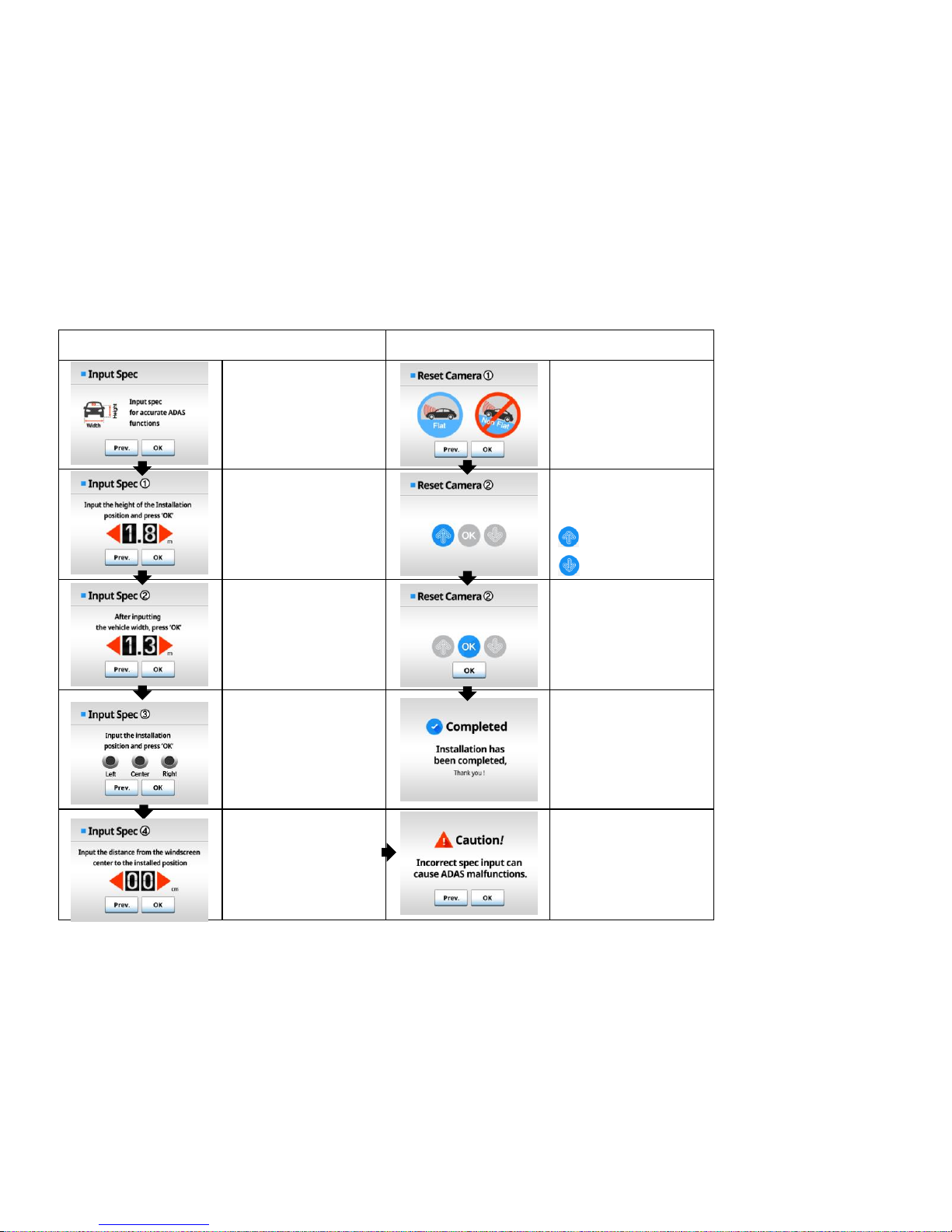
* Input Spec * Camera setting
To perform ADAS
properly , input your
vehicle specifications,
Press OK to continue
To calibrate camera
angle correctly, make
sure the vehicle is
parked on the flat
ground ,
Press OK to continue
Input the installed height
from the ground by
pressing the arrow
button .
Press OK after inputting
the value
Adjust the camera lens
angle by following the
arrow guide
: turn upward .
: turn downward
Input the exterior width
of vehicle by pressing
the arrow button .
Press OK after inputting
the value
OK button will be ON
with the acoustic alarm
when calibration is done
correctly.
Press OK to continue
From the driver’s point
of view, select the
installation position,
Press OK to continue
Setup has been
completed
Input the distance from
the center of windshield
to the installed position
by pressing the arrow
button.
Press OK to continue
If spec input is not
properly done, it may
affect ADAS
performance.
If inputted correctly,
press OK to continue .
[Camera Settings]

∙REC shows the video is being recorded
Center
Number
If a front vehicle is detected , HMW time will be indicated in Green .
When warning signal is generated, TTC will turn Red. ( 0.7 as shown
in the image )
A Red vehicle icon will appear when generating FCW signal
Left
Number Shows the vehicle speed (’80’ as shown in the image)
The horizon guide line
shows the lane lines are being detected. When it generates LDW
signal, the lane lines will turn red.
Home Button: Switches to the main menu
Camera Button: will change between Front and Rear camera views
FCW Button : turns ON/OFF FCW function.
LDW Button : turns ON/OFF LDW function.
FCDA Function : turns ON/OFF FCDA function.
[Screen Types & Explanation]
Front Monitoring Live-view Mode
* In the front monitoring mode, touch the LCD screen to switch to
ADAS display mode

•In the front monitoring live view mode, touch the LCD
screen to switch to ADAS Display Mode
•Indications
- LDW : When lane lines are detected , the lines in the display
turn Green , the violated line will turn Red .
- FCW : When a front vehicle is detected , the vehicle icon will
appear. The vehicle will turn Red when generating a warning
signal .
- Collision Warning : The red vehicle icon will blink twice .
- FCDA : The Green Vehicle icon will blink twice
- HMW Time to collision : indicted at the center of screen
- Vehicle Speed: indicated on the left side of screen as a number
•Press ADAS display screen a second time to go into
power-saving mode and press again to switch to the
Front Monitoring mode.
•The video recording function works properly even in
ADAS Display Mode and Power-saving Mode.
ADAS Display Mode
Menu Guide
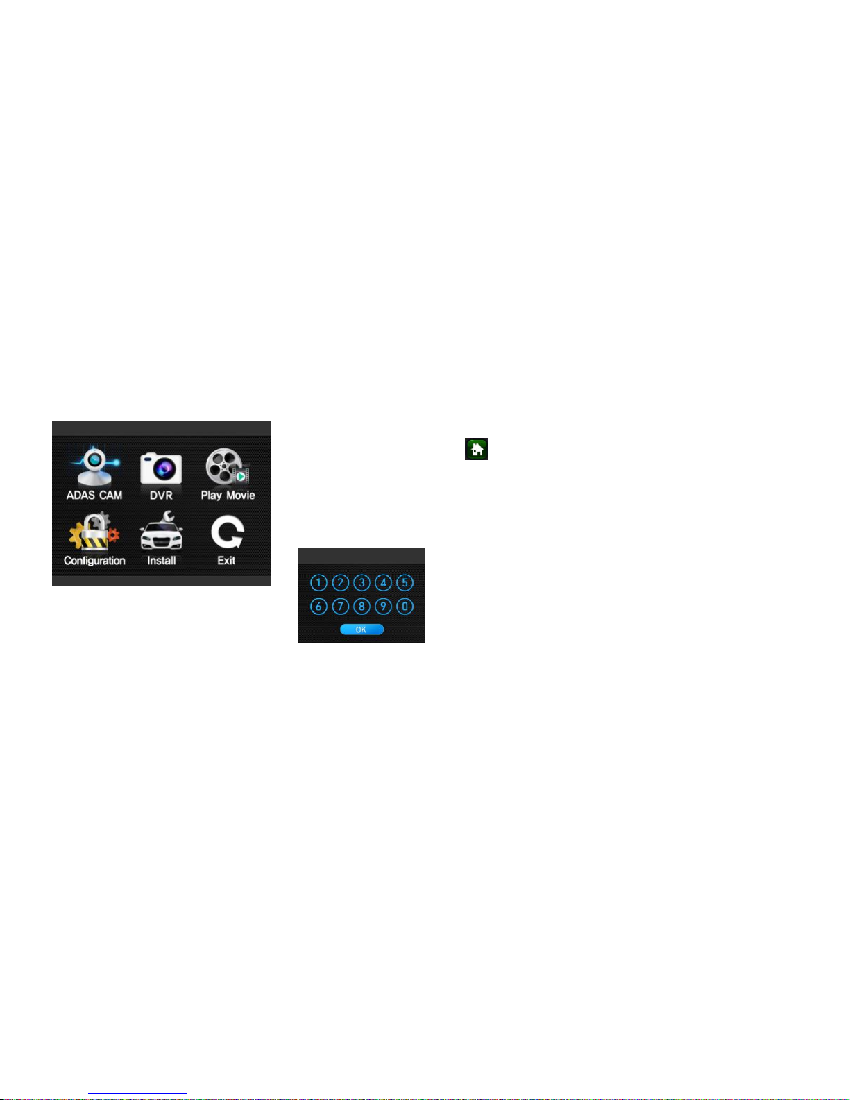
[Basic Menu]
•The Basic Menu screen will appear when pressing the
side M button or bottom home button of LCD.
•Press each icon to enter into corresponding setting
menu .
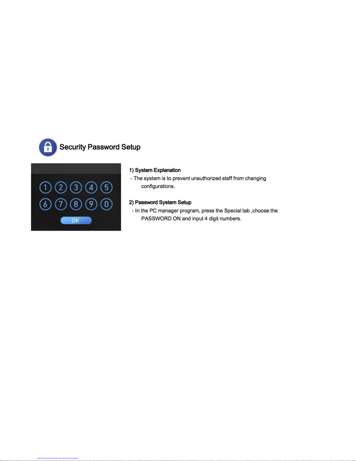
* If Password system is activated , password input screen will appear .
* The Recording function does not work in the menu mode .
1) ADAS CAM : Turn ADAS functions ON/OFF and configure operations.
2) DVR : Change settings relevant to recording , monitoring and resolution
3) Playback : Play recorded videos
4) Configurations : Change settings of system volume , voice alarm ,operation environment and
SD card data format
5) Vehicle Type Setting : Choose the vehicle type and change the installation position
6) Exit : Return to the front monitoring mode and start recording function
User can enter into each functional setting in the basic menu screen.
[Password Input Screen]
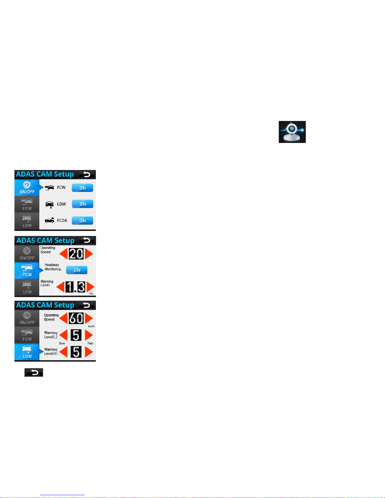
[ADAS CAM]
In ADAS Setup menu, it is possible to change settings of FCW and LDW.
1) Operating Settings
•Each function can be turned ON/OFF
•Touch the button to switch between ON and OFF
2) FCW
•Operating Speed : press the Left / Right arrow to change
-Default value 20km/h, adjustable from 10 ~ 80(km/h)
•HMW : The warning function is to keep a safe distance between vehicles .
•Warning Sensitivity: If the value of Warning Level gets bigger , the warning will
respond faster.
3) LDW
•Operating Speed : press the Left / Right arrow to change
- Default value 60km/h, adjustable from 40 ~ 80(km/h)
•Warning Sensitivity: can be adjustable from 1~9, If the value of Warning Level
gets bigger, the warning will respond faster.
.
* : return to the previous menu
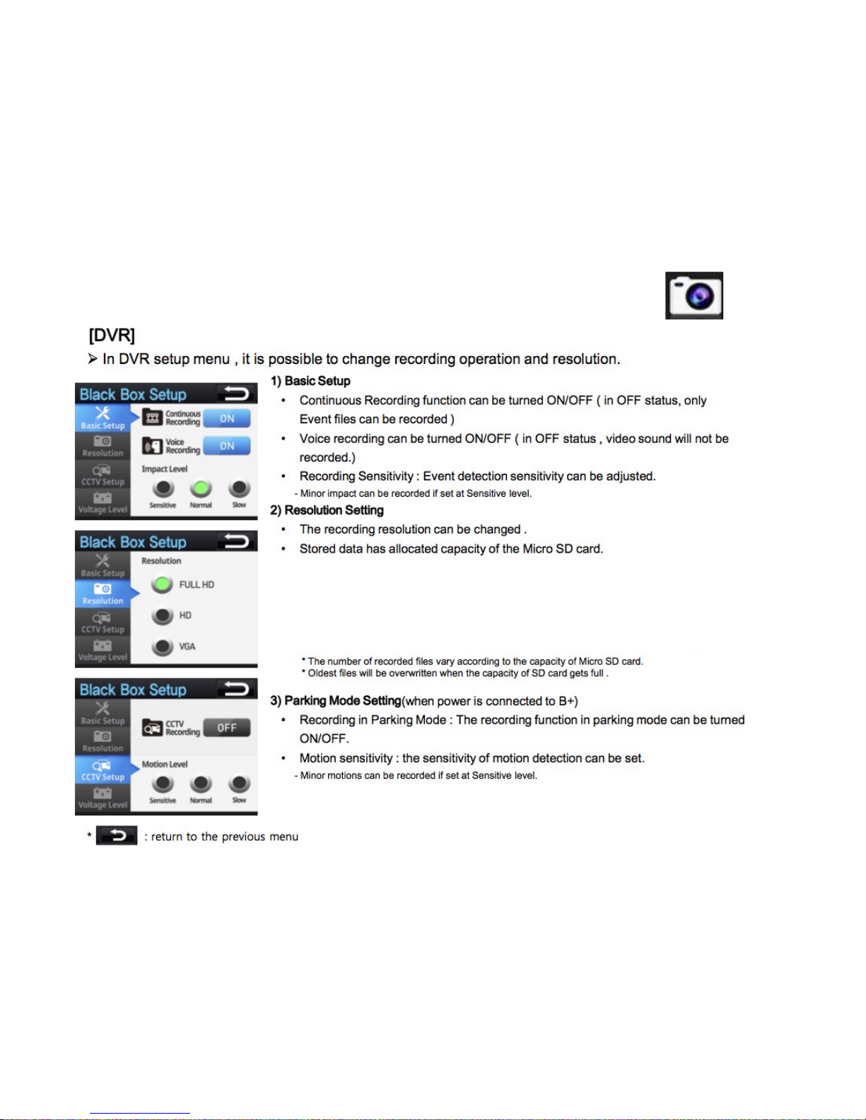
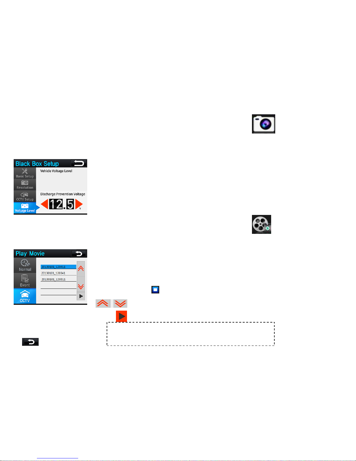
[DVR]
In DVR setup menu , it is possible to change recording operation and resolution.
4) Voltage Setup
•It is recommended to measure the voltage level at the ACC On, and then input
the prevention voltage value.
* If prevention voltage value is below 12V, the vehicle battery could be discharged.
*: return to the previous menu
[Play Movie]
The recorded Video files in modes of Continuous/ Event / Parking can be checked instantly.
1) Continuous / Event/ Parking
•Continuous : Select and check continuously recorded files
•Event : Select and check the event files recorded during driving and parking
•Parking: Select and check recorded files in parking mode
•Select the file and press the play button to check
•When pressing stop button, it will return to the file list page .
: scroll upward & downward to change pages.
: play the selected video file
* User can check recorded video files with ease via PC Data Manager program; It is
possible to check acceleration data , vehicle coordinate and other relevant information via
PC Data Manager program. *

[Configuration]
In Configuration menu , the operation settings can be configured .
1) Volume Control
•Speaker Volume Adjustment : the speaker volume can be adjusted. (0~15)
•MIC Volume Adjustment : the MIC input volume can be adjusted . (0~15)
2) Voice Alarm
•Event Recording : the voice message < start event recording >will be generated
•HMW : HMW signal will be generated with the voice message < watch out > .
•LDW : The voice message < be careful of Left/Right lane > will be generated.
•FCDA: The voice message <Check ahead > will be generated.
* Even when voices are turned off , warning alarms still be generated.
* FCW only generates the alarming sound without the voice guide .
3) SD Card Format
•Delete all the data stored in Micro SD to maintain the file system.
* Critical event files should be stored separately prior to SD card data format .
*SD card data format should be done in Configuration menu or via manager program . Notice that
general format method via PC can cause data format incompatibility.
*: return to the previous menu

4) System Setup
•LCD setting : sets LCD screen display and Screen OFF mode.
•LCD display : turns ON/OFF speed, speed unit, smart UI, and horizontal line
on the display.
•Language : language can be changed through Language Pack Update of
the PC Manager.
•System info : to check system information and initialize the system
4-1) LCD setting
•Select View : It sets up the LCD screen display mode.
- Front: It displays only the image of the front camera of the main body.
- Rear: It displays only the image of the rear camera of the main body.
- PIP: It displays front and rear images simultaneously.
*Rear/ PIP screens are supported only when the secondary camera is connected.
•Screen Save
- sets up LCD display status.
- Even in Always On state, different modes can be switchable in-between Front monitoring →
ADAS display → Screen OFF by touching the LCD.
4-2) LCD Display
•Speed: When ON is selected, it displays the speed values on LCD.
•Unit: It selects the speed unit
•Smart Car: When ON is selected, ADAS UI appears in Image Monitoring
mode.
•Horizontal line: When ON is selected, horizontal line guide line appears in
Image Monitoring mode.
*: return to the previous menu
[Configuration]

4-3) Language
•The default language is English, other language can be applied through the
PC Manager.
4-4) System Info
•User can check Version information of firmware and hardware
•When Reset Setup button is pressed, the values stored in the system
will be initialized, and the system will enter into Install Mode.
* : return to the previous menu
[Configuration]
Table of contents
Other BrandMotion Automobile Electronic manuals

BrandMotion
BrandMotion FLTW-7617 User manual

BrandMotion
BrandMotion AHDS-7810v2 User manual

BrandMotion
BrandMotion AVMS-3700v3 User manual

BrandMotion
BrandMotion Curb Alert Park View Pro 5000-CA6 User manual

BrandMotion
BrandMotion AVMS-3604 User manual

BrandMotion
BrandMotion 9002-2738 User manual

BrandMotion
BrandMotion 5000-CA14 User manual
Popular Automobile Electronic manuals by other brands


GU Electronic
GU Electronic MR-PAS-T-160129 manual

Strongman Tools
Strongman Tools Telford Installation manual & operation instructions

Nav TV
Nav TV MOST-HUR MB user guide

Bully Dog
Bully Dog Power Pup installation manual

VDO
VDO TEMPERATURE GAUGE installation instructions

Murphy
Murphy PowerView PV1000 Hardware installation manual