OWL VS-400-H User manual

2
INTRODUCTION
TABLE OF CONTENTS
CONTACT INFORMATION
Address: Phone: Internet:
Optical Wavelength Laboratories, Inc. 262-473-0643 OWL-INC.COM
N9623 US Hwy 12
Whitewater, WI 53190
SECTION 1: INTRODUCTION
Before You Begin . . . . . . . . . . . . . . . . . . . . . . . . . . . . . 3
About This Manual . . . . . . . . . . . . . . . . . . . . . . . . . . . . 3
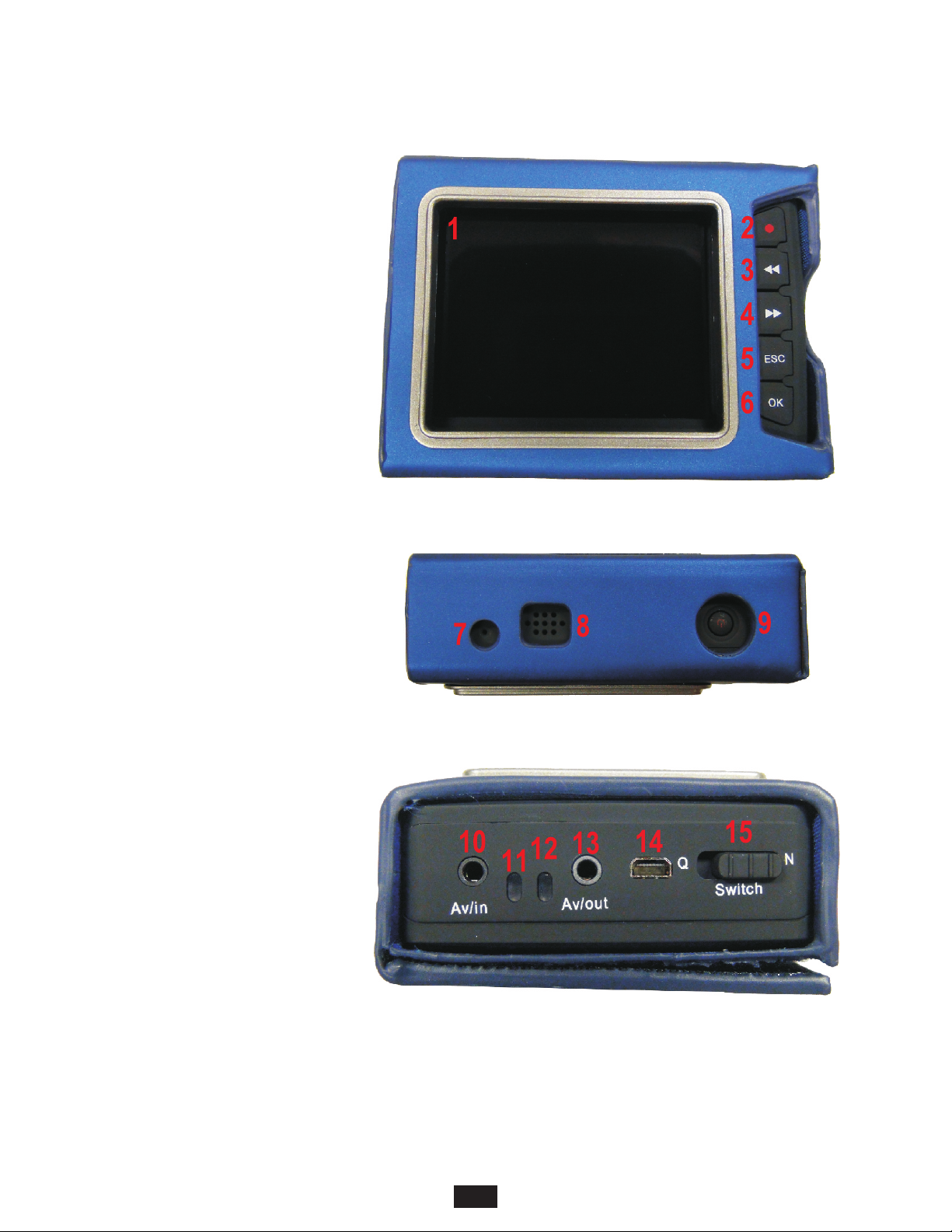
Description . . . . . . . . . . . . . . . . . . . . . . . . . . . . . . . . 4
Viewer. . . . . . . . . . . . . . . . . . . . . . . . . . . . . . . . . . . 5
SECTION 2: OPERATION
Power ON/OFF . . . . . . . . . . . . . . . . . . . . . . . . . . . . . . 6
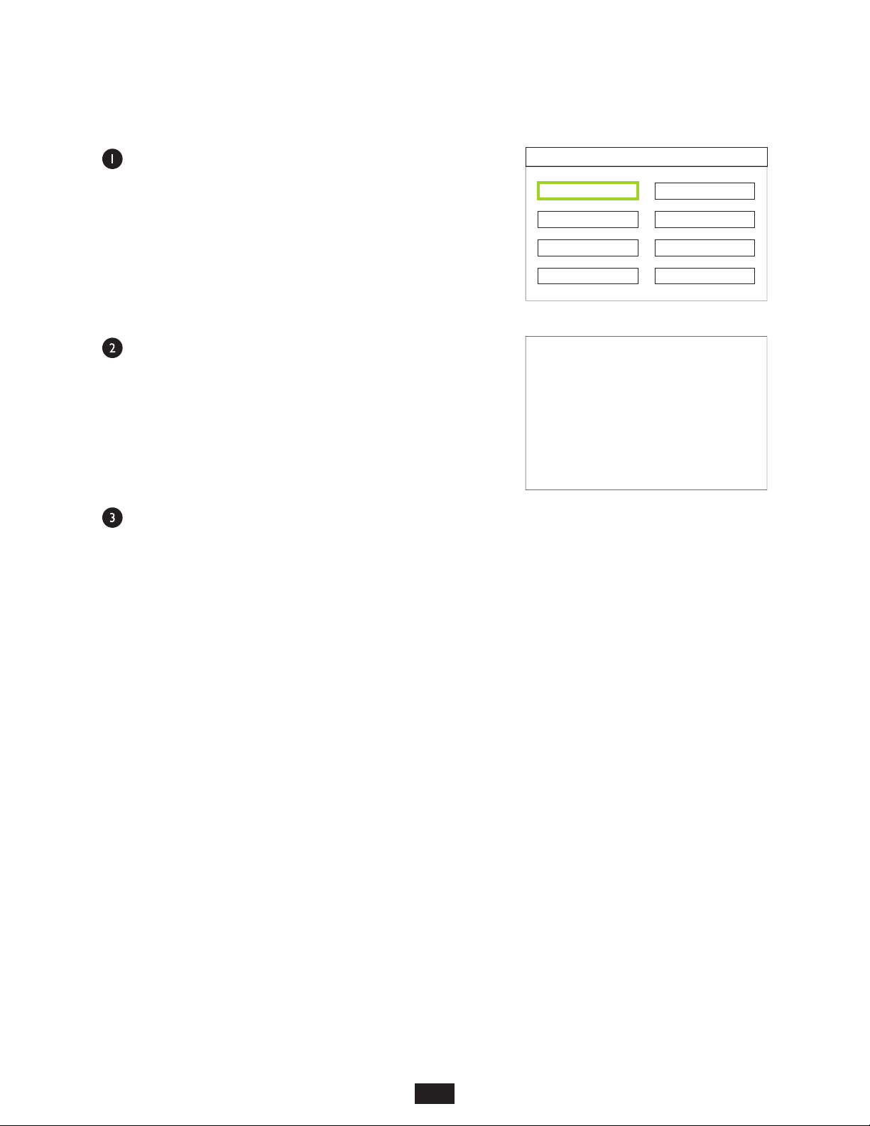
Initial System Setup . . . . . . . . . . . . . . . . . . . . . . . . . . . . 6
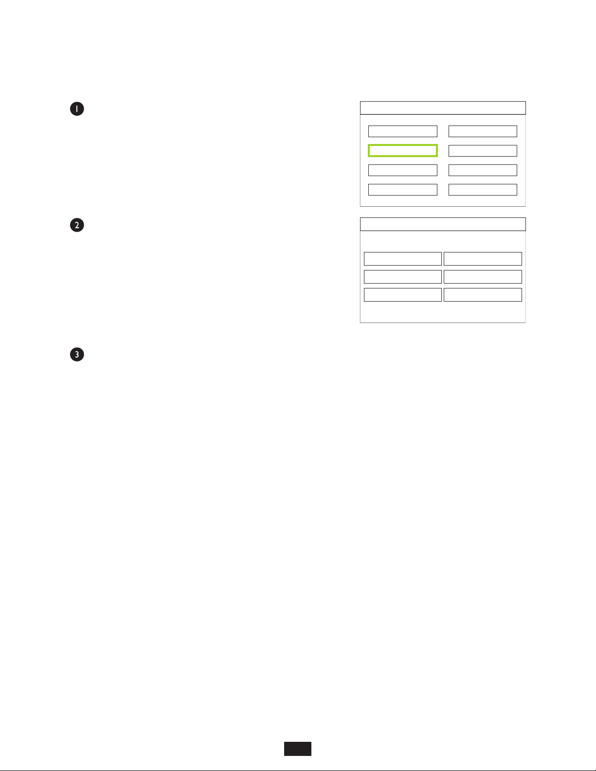
Storage Select . . . . . . . . . . . . . . . . . . . . . . . . . . . . . 7
Storage Info. . . . . . . . . . . . . . . . . . . . . . . . . . . . . . . 8
Format . . . . . . . . . . . . . . . . . . . . . . . . . . . . . . . . . 9
System Time Setting. . . . . . . . . . . . . . . . . . . . . . . . . . . 10
Display Output Setting . . . . . . . . . . . . . . . . . . . . . . . . . . 11
Brightness . . . . . . . . . . . . . . . . . . . . . . . . . . . . . . . 12
Language. . . . . . . . . . . . . . . . . . . . . . . . . . . . . . . . 13
Default . . . . . . . . . . . . . . . . . . . . . . . . . . . . . . . . . 14
Viewing Fiber Endfaces . . . . . . . . . . . . . . . . . . . . . . . . . . 15
Saving Endface Images . . . . . . . . . . . . . . . . . . . . . . . . . . 16
Retrieving Endface Images . . . . . . . . . . . . . . . . . . . . . . . . 17
Deleting Endface Images . . . . . . . . . . . . . . . . . . . . . . . . . 17
Charging the Battery. . . . . . . . . . . . . . . . . . . . . . . . . . . . 18
SECTION 3: CONNECTING THE VIDEOSCOPE TO PC/LAPTOP
Downloading Images to PC/laptop . . . . . . . . . . . . . . . . . . . . . 19

3
INTRODUCTION
BEFORE YOU BEGIN
All personnel testing optical fibers should be adequately trained in the field of fiber optics before using any fiber
optic test equipment.
If the user is not completely familiar with testing fiber optics, they should seek competent training. Such training
can be acquired from a variety of sources, such as local hands-on training classes.
Valuable information about fiber optic testing can also be gathered from reading printed literature carefully or by
thoroughly reading supplied operations manuals.
Fiber optic testers vary from other types of test equipment due to issues such as:
1) standards-based testing
2) proper fiber optic test procedures (FOTPs)
3) "zeroing" or referencing of power levels
4) determining the correct link budget to pass or fail by
Complete understanding of each of these issues is critical for performing proper fiber optic tests.
Throughout this manual you will find various symbols that assist with understanding the procedures outlined in
this manual. Below is a list of these symbols and a short description of their purpose:
Shows a helpful tip that will make a procedure go more smoothly
Tells the user some useful information about the successful completion of a procedure
Warns the operator of a potentially dangerous condition
ABOUT THIS MANUAL

4
INTRODUCTION
DESCRIPTION
The VS-400-H is a hand-held video microscope with 400x magnification, allowing for inspection of both
multimode and singlemode fiber connector endfaces and optical ports for cleanliness and quality.
REQUIREMENTS
A PC or laptop equipped with a USB port is required for downloading captured endface and port images from
the VS-400-H.
ADVANTAGES
Video microscopes offer three distinct advantages over traditional direct-view microscopes:
Eye safety. Even with IR filters and other eye safety precautions, viewing endfaces and ports
through a direct-view scope can be harmful to the eyes, due to high-intensity optical radiation
directly entering the eye. Video microscopes completely isolate the eye from potentially dangerous
incoming light, which instead falls upon a small video camera.
Large viewing area. Images on a video screen are much larger than when viewed through a direct-view
scope, and thus easier to see.
Larger viewing area also reduces eye strain caused by squinting through a viewfinder.
Image capture. Digital images of fiber endfaces/ports are stored in internal memory. Stored traces can be
downloaded to hard disk for later retrieval.

VIEWER
5
INTRODUCTION
1 LCD Display
2 Video record button
3 Left arrow button
4 Right arrow button
5 Back/return button
6 Confirm button
7 Microphone
8 Speaker
9 Power / image capture button
10 AV / Probe input
11 Charging indicator LED
12 Power indicator LED
13 AV / Probe output
14 USB connector
15 Lock

6
OPERATION
POWER ON/OFF
Press and hold the POWER button to power ON and OFF. The unit will vibrate
when powering on and off.
When powering ON, the unit will vibrate continuously if the probe is not
properly connected.
While the unit is powered on, the blue power indicator LED will be lit.
Upon initial startup, a video test screen will briefly appear, then the display
will show the image coming from the probe.
INITIAL SYSTEM SETUP
Before using the videoscope for the first time, it is recommended to configure the user preferences found in the
System Settings menu.
1) Press ESC.
2) Use arrow keys to highlight the “gear” icon.
3) Press OK.
From the System Setting menu, use the arrow keys to navigate through the menu options.
Storage Select This unit is only equipped with an internally installed SD card.
Storage Info Views the statistics for internal SD card.
Format Allows the user to format the internal SD card.
System Time Setting Sets the time/date stamp in the device. The time/date stamp appears on the LCD
display when inspecting fiber endfaces.
Display Setting Sets the output mode of the videoscope.
Brightness Sets the brightness level of the LCD display.
Language Sets the language option.
Default Resets the videoscope to factory default settings.
System Setting
Storage Select
Storage Info
Format
System Time Setting Default
Language
Brightness
Display Setting

7
OPERATION
STORAGE SELECT
Use the arrow keys to highlight the Storage Select menu
option, then press OK.
Because the unit only includes an internally installed SC
card, only “SD card” will appear in the center of the display.
Press ESC to return to the System Setting menu.
System Setting
Storage Select
Storage Info
Format
System Time Setting Default
Language
Brightness
Display Setting
SD card

8
OPERATION
STORAGE INFO
Use the arrow keys to highlight the Storage Info menu
option, then press OK.
The statistics of the internal SD card will be shown, including
total memory, memory in use, and memory remaining.
Press ESC to return to the System Setting menu.
System Setting
Storage Select
Storage Info
Format
System Time Setting Default
Language
Brightness
Display Setting
SD Card Info
Total Space:
In Use:
Space Free:
1899 M
0 M
1899 M

9
OPERATION
FORMAT
Use the arrow keys to highlight the Format menu option,
then press OK.
To exit without formatting the SD card, highlight No and
press ESC or OK. This will return the user to the System
Setting menu.
To proceed with formatting the SD card, highlight Yes and
press OK. Once formatting is complete, the user will be
returned to the System Setting selection screen.
CAUTION!
Formatting will erase all of the data stored on the SD card.
Press ESC to return to the System Setting menu without selecting an option.
System Setting
Storage Select
Storage Info
Format
System Time Setting Default
Language
Brightness
Display Setting
Format SD Card
Yes
No
Erase all the data ?

10
SYSTEM TIME SETTING
Use the arrow keys to highlight the System Time Setting
menu option, then press OK.
This time and date will appear on the LCD display while
inspecting fiber endfaces.
Press OK to advance to the next value.
Use the arrow keys to change the highlighted value.
NOTE: the time is displayed as a 24-hour clock.
The user will return to the System Setting menu after
pressing OK on the last value.
System Setting
Storage Select
Storage Info
Format
System Time Setting Default
Language
Brightness
Display Setting
System Time Setting
2016 / 07 / 07
16:51
OPERATION

11
DISPLAY OUTPUT SETTING
Use the arrow keys to highlight the Display Setting menu
option, then press OK.
For normal hand-held operations, always use the LCD
Output option.
If you wish to send the output to an external monitor, select
the appropriate TV Output option.
Use the supplied composite video cable to connect the
videoscope to the external monitor.
Press OK to accept the Display Output Setting value and return to the System Setting menu.
System Setting
Storage Select
Storage Info
Format
System Time Setting Default
Language
Brightness
Display Setting
Display Output Setting
LCD Output
OPERATION
TV_NTSC Output
TV_PAL Output
Default option.

12
BRIGHTNESS
Use the arrow keys to highlight the Brightness menu
option, then press OK.
Use the arrow keys to increase or decrease the LCD
brightness.
When finished setting the Brightness, press OK to save the brightness level and return to the System
Setting menu.
System Setting
Storage Select
Storage Info
Format
System Time Setting Default
Language
Brightness
Display Setting
Brightness
OPERATION

13
LANGUAGE
Use the arrow keys to highlight the Language menu option,
then press OK.
It is highly recommended to leave this option set to English.
When finished setting the Language Setting, press OK to save and return to the System Setting
menu.
System Setting
Storage Select
Storage Info
Format
System Time Setting Default
Language
Brightness
Display Setting
Language Setting
OPERATION
English Default option.

4
OPERATION
DEFAULT
Use the arrow keys to highlight the Default menu option,
then press OK.
This menu option allows the user to set the user preferences
to factory defaults.
To exit without re-setting factory defaults, press ESC, or
select No and press OK.
To re-set the videoscope to factory settings, highlight Yes
and press OK.
The user will be returned to the System Setting menu.
System Setting
Storage Select
Storage Info
Format
System Time Setting Default
Language
Brightness
Display Setting
Factory Default Set
Yes
No Default option.
14

OPERATION
VIEWING FIBER ENDFACES
With the unit powered OFF, connect the probe to the side of the
unit.
The probe pins are labeled OUT and IN to correspond with the
OUT and IN jacks on the side of the unit.
Attach the appropriate probe tip according to the connector port
or ferrule size that will be inspected. Several probe tip options are included with the VS-400-H.
Power ON the VS-400-H. The LCD display will initially show a test pattern.
A blank screen will appear that includes the current time and
date in the upper right-hand corner, battery status in the
lower left-hand corner, and video recording time and
memory status in the lower right-hand corner.
Connect the probe to the connector or port to be inspected.
Initially the image may be out of focus.
Using the focus adjustment wheel on the probe, focus the
image on the LCD display.
If any obstructions are found on the image, especially on the
core / cladding area, remove the probe from the connector/port to clean the endface. Then re-connect
the probe to re-inspect.
415
2016/07/07 08:48:23
00:00:00
7380 M
2 08:48:30016/07/07
00:00:00
7380 M
2 08:48:35016/07/07
00:00:00
7380 M

OPERATION
SAVING ENDFACE IMAGES
Once the endface image is sufficiently focused, the user can either capture the image to a video file, or a still
image file.
SAVING VIDEO FILES
Press the Video Record button to begin recording the video.
While recording, the RECORD icon will appear. While the current
video record time counts up, the memory status will decrease
according to the size of the video record file.
Press ESC button to end the video recording.
SAVING STILL IMAGE FILES
Press the power button briefly to save a still image of the endface.
A camera icon will briefly appear in the center of the LCD display,
confirming the image has been saved to memory.
4
16
2 08:48:35016/07/07
00:00:05
7374 M
2 08:48:35016/07/07
00:00:00
7374 M

OPERATION
RETRIEVING ENDFACE IMAGES
From the endface viewer screen, press ESC to enter the main menu screen.
By default, the Check Up option will be selected.
Press the arrow keys to highlight the Playback option, then press OK.
Select VIDEO or PHOTO.
417
Playback
VIDEO PHOTO
Video Playback
• MPEG0001.AVI
A
B
C
D
E
Play OK Select Exit ESC
Photo
• PICT0001.JPG
• PICT0002.JPG
• PICT0003.JPG
C
D
E
Play OK Select Exit ESC
With the arrow keys, select the file to preview.
Press OK to view the file, then press ESC when finished viewing the file.
To delete a file, press the Video Record button, then selectYES to delete.
Press ESC twice to return to the main menu screen.

OPERATION
CHARGING THE BATTERY
4
18
Two re-chargeable battery packs and a battery charger are included
with the VS-400-H.
RE-CHARGING BATTERY PACKS
To re-charge the battery packs, insert the battery pack into the charger
contacts first, then press the other side down until the battery pack is
fully seated.
The battery charger plugs directly into a wall outlet.
REMOVING THE BATTERY PACK FROM THE SCOPE
Power off the main scope unit, then disconnect the probe.
Slide the main unit out from the protective sleeve.
Slide off the battery cover from the back of the unit. Insert the battery pack contacts first then press the other
side down until the battery pack is fully seated.
Replace the battery cover and slide the unit back into the protective sleeve.
Battery charger and battery pack

19
CONNECTING THE VIDEOSCOPE TO PC/LAPTOP
DOWNLOADING IMAGES TO PC/LAPTOP
Connect the VS-400-H to a working USB port on a PC or laptop using the supplied USB cable.
The VS-400-H will connect as USB storage device (similar to a USB flash drive) and will be assigned a drive
letter.
Browse to this drive letter to view the files stored on the VS-400-H.
Three sub-directories will appear, one each for stored audio, image, and video files.
These files may be copied from the VS-400-H to the PC/laptop by using the Copy/Paste function.
Table of contents
Other OWL Laboratory Equipment manuals