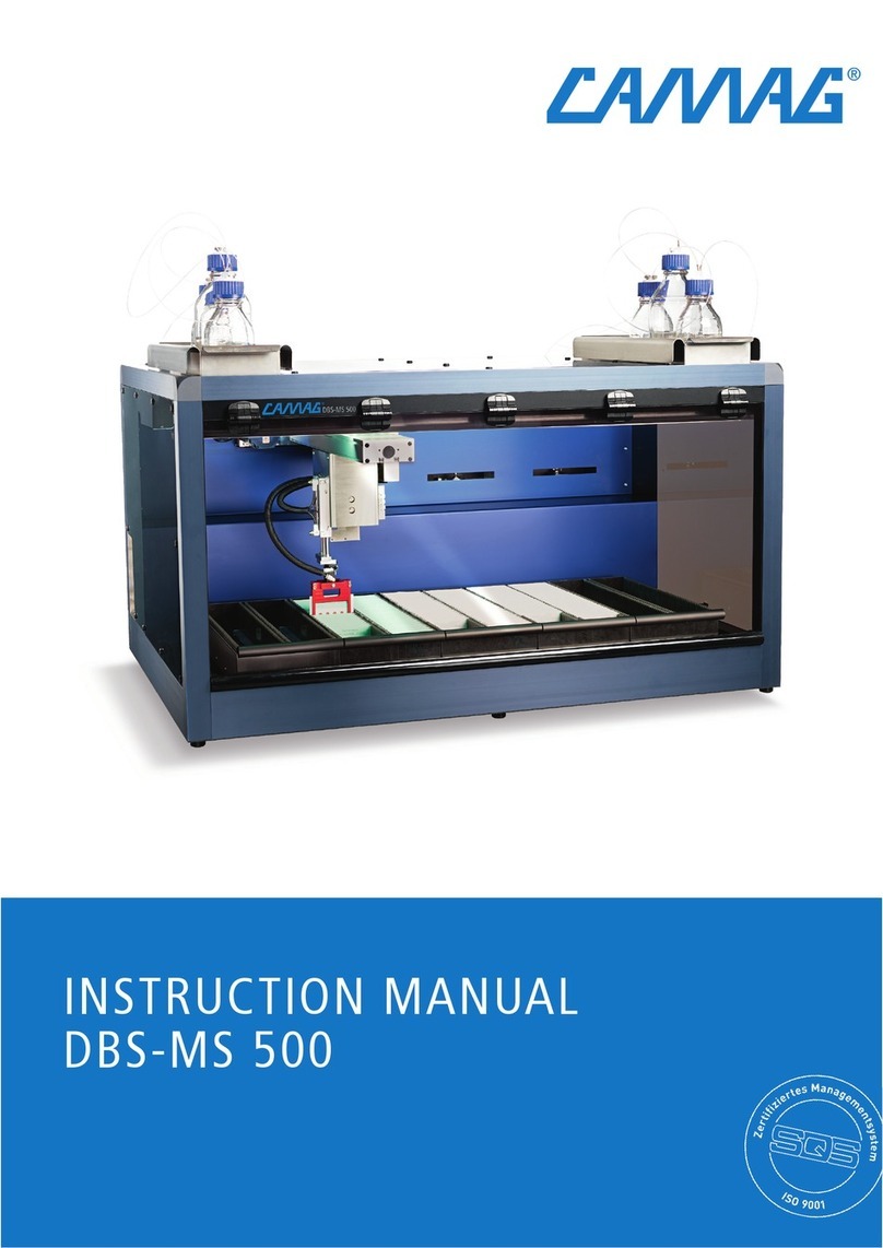
CAMAG DBS-MS 500 User manual

INSTALLATION GUIDE
DBS-MS 500

Content
1Introduction.................................................................................................................................... 3
1.1 Precaution................................................................................................................................ 3
1.2 Parts supplied.......................................................................................................................... 4
2Unpacking/Installation .................................................................................................................. 4
2.1 Removal of shipping protection............................................................................................... 4
2.2 Installation of the instrument.................................................................................................... 6
Fluidics............................................................................................................................................. 6
Electrics........................................................................................................................................... 8
Software........................................................................................................................................... 8
Priming............................................................................................................................................. 9
3Hardware Connections ............................................................................................................... 10
3.1 CAMAG DBS-MS500 contact closure................................................................................... 10
3.2 Connectors on measurement systems.................................................................................. 11
Agilent APG remote interface........................................................................................................ 11
AB Sciex AUX/ I/O interface.......................................................................................................... 12
Shimadzu event interface.............................................................................................................. 12
Waters Xevo TQD with AQUITY UPLC system ............................................................................ 13
Thermo system under Xcalibur...................................................................................................... 14
3.3 Connection examples............................................................................................................ 16
LC/MS system of Agilent and Sciex .............................................................................................. 16
LC/MS system of Waters and Sciex.............................................................................................. 18
Thermo system under Xcalibur...................................................................................................... 19
3.4 Coupling a PAL fraction collector .......................................................................................... 19
4Software coupling ....................................................................................................................... 22
4.1 Preparation of the network configuration............................................................................... 22
4.2 Masslynx coupling................................................................................................................. 23
4.3 Analyst coupling .................................................................................................................... 24
4.4 Xcalibur coupling ................................................................................................................... 26
Introduction
Installation guide, Nov-18 3
1 Introduction
The main function of the DBS-MS 500 is the fully automated solvent extraction of dried
blood spot samples for detection by a mass spectrometer. The samples are delivered
on cards, with up to four spots per card. To ensure reliable automated sample
extraction and handling, these cards are stored in removable racks which hold them in
exactly defined positions inside the instrument. The instruments handling module picks
cards out of the rack and carries them to an image processing system and then to an
optional station for the application of the internal standard before delivering the card to
the extraction unit. Finally, the sampled cards are stored back in the rack position they
were picked from. With the image processing system, multiple quality factors and
identification features of each card will be measured and checked to ensure the correct
spot is sampled and that this spot has not been incorrectly spotted, or previously
sampled. The exact positioning of the card in the extraction unit will be made according
to these values. The optional IS working solution will be applied at the internal standard
station to only the sample to be extracted. At the extraction unit the analyte will be
eluted out of the card using the preferred solvents (specific extraction solvent mixture).
This extract will then be delivered to the HPLC-MS system for further separation and
detection as required. Handling and extraction processes are to be designed for
maximum robustness and minimum carryover.
1.1 Precaution
Before installing/using the instrument, check the section “Precaution” in the instruction
manual
When working with analytical instrumentation, you must know the potential hazards of
using chemical solvents. Many organic solvents, mobile phases and samples are
harmful to health. Be sure that you know the toxic and infectious properties of all
substances you are using.
This sign draws attention to the fact that failure to take note of the accompanying
information (on instrument, in this manual and the respective instruction manual) may
result in damage of the instrument
This sign draws attention to the potential risks due to pathogenic or genetically
modified organisms and serves to reduce the dispersal and uncontrolled multiplication

Unpacking/Installation
Installation guide, Nov-18 4
of organisms and to protect people from unintentional infection. If handling with such
substances be aware of the applicable guidelines.
Be aware of the special risks when opening the instrument
Use only original CAMAG spare parts
Switch off the instrument before you open the instrument
1.2 Parts supplied
Check with reference to the parts supplied section in the instruction manual for
complete shipment of instrument and accessories.
2 Unpacking/Installation
•Check the installation environment according the Environment Specification (CAMAG
SOP 402)
•Lift the instrument with the necessary care (4 persons) out of its packaging.
•Place it according the Environment Specification
2.1 Removal of shipping protection
1. Loosen the cable tie
2. Remove the spring of the gripper arm
3. Remove the 2 knurled screws and the gripper arm holder
4. Remove the 3 knurled nuts and move the plate of the shipping protection to the left

Unpacking/Installation
Installation guide, Nov-18 5
5. Move the plate of the shipping protection to the front and
6. Mont the spring of the gripper arm

Unpacking/Installation
Installation guide, Nov-18 6
2.2 Installation of the instrument
•Mount the 5 racks (insert the backside of the racks first)
Fluidics
During usage, empty the waste canister on a regular base. If you refill the
extraction/rinsing bottles check the solvent level of the waste canister.
Make sure all bottles are clearly and correctly labelled with their content.
CAMAG strongly recommends using degassed solvents only to reduce micro-bubbles
in the system.
•Connect the waste canister according below figure
Fig. 1: Waste canister connection
•Fill and connect the solvent bottle 1 (500ml, tube “Elution 1” and “E1/R3”) with your
appropriate elution solvent
•Fill and connect the solvent bottle 2 (500ml, tube “Elution 2” and “E1/R3”) with your
appropriate elution solvent
•Fill and connect the rinsing liquid bottle 1 (1000ml, tube “Rinsing R1”) with your
appropriate rinsing solvent
•Fill and connect the rinsing liquid bottle 2 (1000ml, tube “Rinsing R2”) with your
appropriate rinsing solvent
•If applicable, fill and connect the internal standards (IS) bottles (25ml, IS1, 2, 3, 4)
with your appropriate standard solution
•Fill and connect the IS rinsing bottle (250ml) with your appropriate solution
•Connect the external system pump with 10-32 fittings to Valve3, port 4; according the
below shown figures
•Connect the MS with 10-32 fittings to Valve 2, port 7; according the below shown
figures
CAMAG strongly recommends keeping the connection as short as possible (no
longer then 2m) to maintain measurement accuracy and quality.

Unpacking/Installation
Installation guide, Nov-18 7
Fig. 2: Valves:Fluid Selection F-V1 /Loop F-V2/ CDM (Controlled Delivery Module) F-
V3
Port 4: From LC Pump
Port 7: To LC/MS system
Fig. 3: Loop valve F-V2 connection scheme

Unpacking/Installation
Installation guide, Nov-18 8
Electrics
Fig 4. Electric connection panel
•Connect the HMI with the instrument (red)
•Connect the air or Nitrogen pressure (>5.5 bar up to 8 bar) with a 6mm outer
diameter hose (purple). Make sure you keep the length of the hose as short and the
diameter as big as possible
•Connect the required contact closure according table 1 (green, additional information
about the contact closure you can find in chapter 3 Hardware Connections of this
document) to your measurement system control
•Connect the power cord (use only the original delivered CAMAG power cord)
•Connect the LAN cable to the computer (for use of CHRONOS software)
•Switch on the unit
Software
Check the user manual of Chronos (by Axel Semrau GmbH& CO KG) for CAMAG for
computer requirements and installation of the software.

Unpacking/Installation
Installation guide, Nov-18 9
Priming
Prior to first use or after a longer period of non-using the instrument, the fluidic has to
be filled with the respective solvents (Priming).
Priming of extraction circuit
•Choose “Manual”
•Choose “Extractor”
•For the extraction pump (Prime EX):
If the system was completely empty, priming can take up to 50 cycles
•For the rinsing pump (Prime Ri): Activate the pump for about 60 sec.
Priming is finished when the pressure of extraction and rinsing pump is stable
(extraction pump only during dosing). If the system was completely empty, priming can
take up to 5 min.
Priming of IS circuit
•Choose “manual”
•Choose “Internal Standard”
•Choose the appropriate IS Bottle
•Set the no of Prime Cycles to 5
•Set the destination parameter to “to waste”
•Activate the priming
•Set the destination parameter to “to Needle”
•Activate the priming
•Repeat the steps above until no more air bubbles are visible in the IS syringe
Priming of IS cleaning circuit
•Choose “manual”
•Choose “Internal Standard”
•Set the time parameter to “5’000” (ms)
•Activate the priming by clicking the “cleaning” button
•Repeat the steps above until a nice and constant jet of IS cleaning solvent is visible
from the IS needle
At the priming stage, watch out for any signs of leakage at the fluidic part of the
instrument.
Your system is now ready to use!

Hardware Connections
Installation guide, Nov-18 10
3 Hardware Connections
Remote control allows easy connection between single instruments or systems to
ensure coordinated analysis with simple coupling requirements.
CAMAG DBS-MS500 is simply to include into an LC/MS System similar to an
Autosampler and uses a contact closure connector to communicate with other parts of
the system. In this Attachment, you find some examples with the most common brands.
3.1 CAMAG DBS-MS500 contact closure
Pin Signal Description
1 NC Relay 1; Loop Inline
(Start signal to LC/MS)
2 NO
3 COM
4 NC Relay 2; DBS Ready
(DBS-MS500 is ready)
5 NO
6 COM
7 IN+ Opto 1; LCMS Ready
(LC/MS is ready)
8 IN-
(GND)
9 IN+ Opto 2; Start NxtExtr
(DBS-MS500 can start next
extraction)
10 IN-
(GND)
11 +24V Power
12 GND Power
Contact closure connector
Legend: NC = normally closed
NO = normally open
IN+ = optical input positive (24V)
IN- = optical input ground (GND)
The loose end cable delivered with the instrument has following connection scheme:

Hardware Connections
Installation guide, Nov-18 11
3.2 Connectors on measurement systems
Agilent APG remote interface
Agilent uses the APG Remote Interface; see following drawings and definitions:

Hardware Connections
Installation guide, Nov-18 12
AB Sciex AUX/ I/O interface
AB Sciex uses the AUX I/O Interface (8); see following drawings and definitions:
Shimadzu event interface
You have to connect a cable between the MAN. INJ. terminal and Dbs500 out signal
“Loop is Inline”; see following pictures:
Back side of Shimadzu Controller CBM-20A/20Alite:

Hardware Connections
Installation guide, Nov-18 13
Waters Xevo TQD with AQUITY UPLC system
For remote control you have to use Connectors I/II of respectively used device (Solvent
Manager or Xevo TQD Mass spectrometer), see following pictures:

Hardware Connections
Installation guide, Nov-18 14
Output signal “Stop Flow” could be used as an “Error” signal to stop DBS-MS 500.
Switch 2-4 are software configurable signals and could be used to send a “Start Next
Sample” signal to the DBS-MS 500. Connect in minimum the DBS-MS 500 signal
“Loop is Inline” to Waters connector II at Pin 1-2.
Thermo system under Xcalibur
Remote connection between DBS-MS 500 and Thermo (use port 1 at the LC)

Hardware Connections
Installation guide, Nov-18 15
Thermo connector to the LC pump
Remote control from LC (output 2) to MS (start in)

Hardware Connections
Installation guide, Nov-18 16
3.3 Connection examples
If you want to use input signals on DBS-MS500 you have to configure this in the
service dialog of the DBS-MS500.
LC/MS system of Agilent and Sciex
Near the main power socket the 12 Pin Contact/Closure Interface Connector of
CAMAG DBS-MS500 can be found. For a minimum wiring you have to connect pin 2/3
of CAMAG connector to pin 1/3 of APG Remote Interface or to pin 21/22 (bridge
between pin 9/10) of Sciex AUX I/O connector. Do not connect APG Remote Interface
and Sciex AUX I/O in parallel. See following drawing:

Hardware Connections
Installation guide, Nov-18 17

Hardware Connections
Installation guide, Nov-18 18
LC/MS system of Waters and Sciex
Near the main power socket, the 12 Pin Contact/Closure Interface Connector of
CAMAG DbsMs500 can be found. For a minimum wiring you only have to connect
wires on Pin 2/3. Do not connect Waters Interface and Sciex AUX I/O in parallel.

Hardware Connections
Installation guide, Nov-18 19
Thermo system under Xcalibur
Note that DBS-MS 500 port 3, 6 and 12 are connected internally within the plug.
3.4 Coupling a PAL fraction collector
Installation of a PAL fraction collector on the DBS-MS500
•Unpacking and installing the hardware
•Unpack the PAL and place it as close as possible to the DBS-MS 500
•Mount the tools on the PAL and connect them accordingly.
oEthernet connection directly into the SWITCH box of the DBS-MS500
oPower and connection cables according to the “PAL RSI User Manual”

Hardware Connections
Installation guide, Nov-18 20
oFluidic capillaries (setup can be changed by adapting the PAL method in the
script editor, not recommended):
16
5
2
3 4
•Insert a 100 µl syringe into the dilutor and prime it
•Connect the interface cable (remote cable) with the DBS-MS500
Pin PAL
Description
Wire color
Pin DBS-
MS500
Description
7
TTL-In 1 Start
Yellow
1
Loop inline (NC)
8
Gnd
Green
3
Loop inline (NC)
3
SW-Out1(NC)
White
9
+24V
4
SW-Out2 (NC)
Broun
11
Next Sample
•Configure the PAL according the “PAL RSI User Manual”
oIP = 172.20.62.35
1. Teach all modules
Menu I/O
SWOut 1
Signal On □
Low Active □
TTL In 1
Signal On □
Debug Time 20 ms
Low Active □
Menu, Input Signal 1
Signal On x
Time 0 ms
TTL In 1
Menu, Output Signal 1
Signal On □
SW Out 1
Dest Aux None
Pulse Duration 2000 ms
Other manuals for DBS-MS 500
1
Table of contents
Other CAMAG Laboratory Equipment manuals

CAMAG
CAMAG AMD 2 User manual

CAMAG
CAMAG ATS 4 User manual

CAMAG
CAMAG ADC 2 User manual

CAMAG
CAMAG ADC 2 User manual

CAMAG
CAMAG DBS-MS 500 User manual

CAMAG
CAMAG UV LAMP 4 User manual

CAMAG
CAMAG LINOMAT 5 User manual

CAMAG
CAMAG TLC-MS INTERFACE 2 User manual

CAMAG
CAMAG NANOMAT 4 User manual

CAMAG
CAMAG Derivatizer User manual