Braun Aesculap GA320 Manual

Aesculap®Acculan 4
Aesculap Power Systems
Instructions for use/Technical description
Acculan 4 Charger GA320
Gebrauchsanweisung/Technische Beschreibung
Acculan 4 Ladegerät GA320
Mode d’emploi/Description technique
Chargeur Acculan 4 GA320
Instrucciones de manejo/Descripción técnica
Cargador Acculan 4 GA320
Istruzioni per l’uso/Descrizione tecnica
Caricabatterie Acculan 4 GA320
Instruções de utilização/Descrição técnica
Carregador Acculan 4 GA320
Gebruiksaanwijzing/Technische beschrijving
Acculan 4 laadapparaat GA320
Bruksanvisning/Teknisk beskrivning
Acculan 4-laddare GA320
Инструкция по примению/Техническое описание
Зарядное устройство Acculan 4 GA320
Návod k použití/Technický popis
Nabíječka Acculan 4 GA320
Instrukcja użytkowania/Opis techniczny
Ładowarka Acculan 4 GA320
Návod na použitie/Technický opis
Nabíjačka Acculan 4 GA320
Kullanım Kılavuzu/Teknik açiklama
Acculan 4 şarj cihazı GA320
사용 설명서 /기술 설명
Acculan 4 충전기 GA320


9
567423
1
8

2
Aesculap®Acculan 4
Acculan 4 Charger GA320
Aesculap®Acculan 4Acculan 4 Charger GA320
Legend
1Charging bays
2Indicator fields for charging bays
3“Power On” indicator (lit up green)
4Product name Acculan 4
5Cover/interlock connections for service. Use is reserved solely for the
manufacturer or authorized service.
6Fuse holder
7Device socket
8Ventilation slots
9Type plate
Symbols on product and packages
Caution
Refers to the necessity for the user to review the
instructions for use for important safety-related infor-
mation, such as warning notices and precautionary
measures, which cannot be attached to the medical
product itself for a variety of reasons.
Follow the instructions for use
“Power On” indicator (lit up green)
Indicator/symbol of the charging bays
Charging progress indicator (illuminated in green)
Indicator/symbol of charging bays "Action request"
symbol (illuminated in orange)
Indicator/symbol of charging bays "Battery change
recommended" symbol (illuminated in orange)
Fuse
Alternating current
Manufacturer’s serial number
Manufacturer and date of manufacture (year)
SN
Labeling of electric and electronic devices according to
Directive 2012/19/EU (WEEE), see chapter on disposal
Date of manufacture
Manufacturer’s batch designation
Manufacturer’s article number
Temperature limit
The temperature limit values to which the medical
product can be safely subjected are designated.
Humidity, limit
Designates the humidity range to which the medical
product can be safely subjected
Air pressure, limit
Designates the atmospheric pressure to which the
medical product can be safely subjected
LOT
REF

3
Contents
1. Applicable to . . . . . . . . . . . . . . . . . . . . . . . . . . . . . . . . . . . . . . . . . 3
2. Intended use . . . . . . . . . . . . . . . . . . . . . . . . . . . . . . . . . . . . . . . . . 3
2.1 Task/Function . . . . . . . . . . . . . . . . . . . . . . . . . . . . . . . . . . . . . . . . 3
2.2 Application Environment . . . . . . . . . . . . . . . . . . . . . . . . . . . . . . . 3
2.3 Set-up location . . . . . . . . . . . . . . . . . . . . . . . . . . . . . . . . . . . . . . . 3
3. Safe handling . . . . . . . . . . . . . . . . . . . . . . . . . . . . . . . . . . . . . . . . 3
4. Product description. . . . . . . . . . . . . . . . . . . . . . . . . . . . . . . . . . . . 4
4.1 Scope of supply . . . . . . . . . . . . . . . . . . . . . . . . . . . . . . . . . . . . . . . 4
4.2 Components required for operation . . . . . . . . . . . . . . . . . . . . . . 4
4.3 Operating principle . . . . . . . . . . . . . . . . . . . . . . . . . . . . . . . . . . . . 4
5. Preparation . . . . . . . . . . . . . . . . . . . . . . . . . . . . . . . . . . . . . . . . . . 5
6. Working with the device . . . . . . . . . . . . . . . . . . . . . . . . . . . . . . . 6
6.1 System set-up . . . . . . . . . . . . . . . . . . . . . . . . . . . . . . . . . . . . . . . . 6
6.2 Safe operation. . . . . . . . . . . . . . . . . . . . . . . . . . . . . . . . . . . . . . . . 6
7. Validated reprocessing procedure . . . . . . . . . . . . . . . . . . . . . . . . 7
7.1 General safety notes . . . . . . . . . . . . . . . . . . . . . . . . . . . . . . . . . . . 7
7.2 General information . . . . . . . . . . . . . . . . . . . . . . . . . . . . . . . . . . . 7
7.3 Preparation before cleaning. . . . . . . . . . . . . . . . . . . . . . . . . . . . . 7
7.4 Cleaning/disinfection . . . . . . . . . . . . . . . . . . . . . . . . . . . . . . . . . . 8
7.5 Wipe disinfection for electrical devices without sterilization. . 8
7.6 Inspection, maintenance and checks. . . . . . . . . . . . . . . . . . . . . . 9
8. Maintenance . . . . . . . . . . . . . . . . . . . . . . . . . . . . . . . . . . . . . . . . . 9
9. Troubleshooting list . . . . . . . . . . . . . . . . . . . . . . . . . . . . . . . . . . . 9
10. Replacing fuses . . . . . . . . . . . . . . . . . . . . . . . . . . . . . . . . . . . . . . . 10
11. Technical Service. . . . . . . . . . . . . . . . . . . . . . . . . . . . . . . . . . . . . . 10
12. Accessories/Spare parts . . . . . . . . . . . . . . . . . . . . . . . . . . . . . . . . 10
13. Technical data . . . . . . . . . . . . . . . . . . . . . . . . . . . . . . . . . . . . . . . . 10
13.1 Performance data, information about standards . . . . . . . . . . . . 10
13.2 Ambient conditions. . . . . . . . . . . . . . . . . . . . . . . . . . . . . . . . . . . . 11
14. Disposal . . . . . . . . . . . . . . . . . . . . . . . . . . . . . . . . . . . . . . . . . . . . . 11
15. Distributor in the US/Contact in Canada for product
information and complaints. . . . . . . . . . . . . . . . . . . . . . . . . . . . . 11
1. Applicable to
►For item-specific instructions for use and information on material
compatibility, see also the Aesculap Extranet at
https://extranet.bbraun.com
2. Intended use
2.1 Task/Function
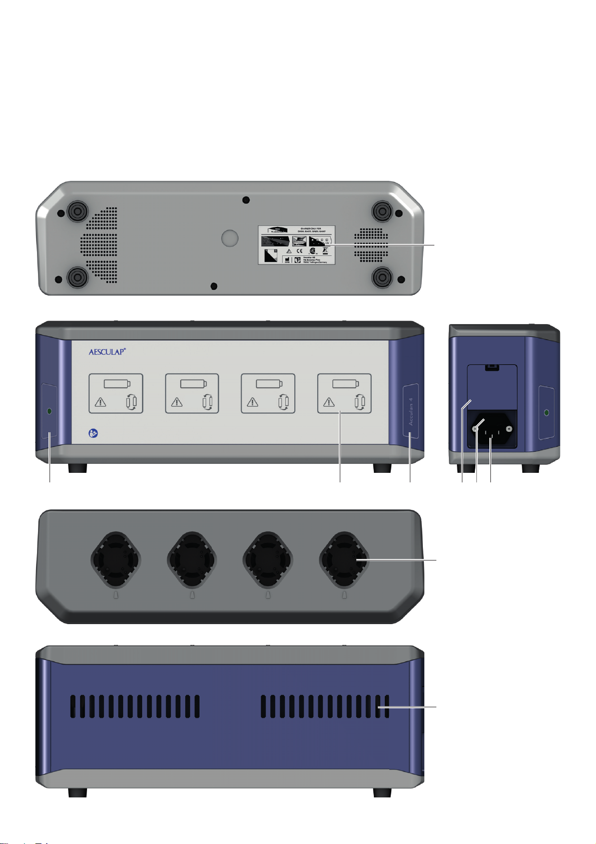
The charger is used to charge and monitor the Aesculap Acculan 4 Li-
Ionen battery GA346. The Aesculap Acculan 3Ti NiMH battery GA676 and
GA666 can also be charged and monitored with this charger.
2.2 Application Environment
The charger is approved for operation in confined speces, outside of the
patient environment, in the non-sterile zone and outside of the explosion
risk zone (such as areas with pure oxygen or anesthesia gases).
2.3 Set-up location
The charger must be placed on a table or shelf that ensures stability.
The charger may not be subjected to direct sunlight or moisture.
3. Safe handling
CAUTION
Federal law restricts this device to sale by, or on order of a physician!
►Inspect the new product after removing its transport packaging and
prior to first use to ensure it is in good working order.
►See “Information on electromagnetic compatibility (EMC) for
Acculan 4 charger" TA022461; see Aesculap Extranet at
https://extranet.bbraun.com
DANGER
Risk of death by electric shock!
►Do not open the product.
►Connect the product only to a grounded power
supply.
WARNING
Risk of injury and damage to property due to
improper handling of the product!
►Observe the instructions for use of the
Acculan 4 battery and of the Acculan3 Ti
rechargeable battery.
►Follow the instructions for use of all products
used.
WARNING
Risk of injury and material damage if this product
is not used as intended!
►Use the product only in accordance with the
intended purpose.

4
Aesculap®Acculan 4
Acculan 4 Charger GA320
Note
The Acculan 4 Charger GA320 fulfills the requirements of CISPR 11, Class A.
►To prevent damage caused by improper setup or operation, and to not
compromise the manufacturer warranty and liability:
– Use the product only according to these instructions for use.
– Follow the safety and maintenance instructions.
– Only combine Aesculap products with each other.
– Follow the application advisories acc. to standard, see Extracts from
relevant standards.
►Ensure that the product and its accessories are operated and used only
by persons with the requisite training, knowledge, or experience.
►Keep the instructions for use accessible for the user.
►Always adhere to applicable standards.
►Ensure that the electrical installation of the room is consistent with
the requirements of IEC/DIN EN.
►Do not pull any of the cables by the actual cable but only by the con-
nector when disconnecting the device from power.
►Do not operate the product in explosion-hazard areas.
►Use the product in non-sterile zones only.
►Do not use the product if it is damaged or defective.
►Set aside the product if it is damaged.
►Follow the instructions for use of the corresponding Acculan battery.
4. Product description
4.1 Scope of supply
4.2 Components required for operation
■Acculan 4 Charger
■Power cable, see accessories
4.3 Operating principle
The Acculan 4 Charger is designed for a mains voltage range of 100 V~ to
120 V~ (0.8 A to 0.7 A) or 220 V~ to 240 V~ (0.5 A to 0.4 A). The mains
voltage is converted into a protective extra-low voltage. To make the
charger ready for operation, connect it to mains power using the mains
power cord. No other action is required to activate or deactivate the con-
sole. The charger performs a self-test, which takes approx. 3 seconds. Dur-
ing this test, all indicator elements at the front panel of the charger are
illuminated.
Charging bays
The Acculan 4 Charger has four separate, independent slots that are com-
patible with the Acculan 4 battery GA346, and with the Acculan battery
GA676 and GA666. Each charging bay has an indicator field on the char-
ger front panel assigned to it.
Automatic start of charging process
Charging starts automatically as soon as a battery is inserted in a charging
bay. The charging time in all four charging bays depends on the charge
state and capacity of the batteries.
Li-Ion battery GA346
Charging principle
The batteries are charged very gently. The charge state of the battery is
continuously monitored throughout charging. Monitoring of the charging
curve ensures that the battery is fully charged without overcharging.
Additionally, the battery temperature and charging time are monitored as
well.
The Li-Ionen batteries GA346 undergo an automatic battery check. This
check assesses the battery condition.
If the "Battery change recommended" symbol lights up, replacement of
the battery is recommended. This battery can still be used. However, it
must be taken into account that an intraoperative battery change may be
necessary due to the reduced performance, or a safety function may acti-
vate.
Art. no. Designation
GA320 Acculan 4 Charger
TA014535 Instructions for use, Acculan 4 Charger GA320
C63401 Instructions for use, Validated Reprocessing Procedure,
German
C63402 Instructions for use, Validated Reprocessing Procedure,
English

5
Battery temperature
Each charging bay is equipped with a fan, which works independently of
the battery temperature. The charging of the battery is aborted at a bat-
tery temperature of >45 °C. Excessive battery temperature is indicated by
the “Action request” symbol illuminated in indicator field. When the bat-
tery temperature drops, the "Action request" symbol in indicator field 2
still remains illuminated. The battery must be removed from the respective
charging bay and plugged in again. to restart charging.
Charging time
Charging is stopped as soon as the maximum charging time is reached. The
permanent monitoring of the battery also allows detecting faults in the
battery block. When a battery fault or a charging fault is detected, this is
indicated by the “Action request” symbol illuminated in indicator field 2
and charging is aborted.
NiMH battery GA676 and GA666
Charging principle
The batteries are charged very gently with constant current pulses. The
charge state of the battery is continuously monitored throughout charg-
ing. Monitoring of the charging curve ensures that the battery is fully
charged without overcharging. Additionally, the battery temperature and
charging time are monitored as well.
The NiMH GA676 and GA666 batteries undergo an automatic battery
check. This check assesses the battery condition.
If the "Battery change recommended" symbol lights up, replacement of
the battery is recommended. This battery can still be used. However, it
must be taken into account that an intraoperative battery change may be
necessary due to the reduced performance, or a safety function may acti-
vate.
Battery temperature
Each charging bay is equipped with a fan, which works independently of
the battery temperature. The charging of the battery is aborted at a bat-
tery temperature of >47 °C. Excessive battery temperature is indicated by
the “Action request” symbol illuminated in indicator field 2. When the
battery temperature drops, the "Action request" symbol in
indicator field 2still remains illuminated. The battery must be removed
from the respective charging bay and plugged in again. to restart charg-
ing.
Charging time
Charging is stopped as soon as the maximum charging time is reached. The
permanent monitoring of the battery also allows detecting faults in the
battery block. When a battery fault or a charging fault is detected, this is
indicated by the “Action request” symbol illuminated in indicator field 2
and charging is aborted. After a successfully completed charging process,
the charger switches to trickle charging.
Note
The Acculan 4 Charger has a function for maintaining the maximum charge
when a battery is left in the charger after complete recharging.
5. Preparation
Non-compliance with the following instructions will preclude all respon-
sibility and liability in this respect on the part of Aesculap.
►When setting up and operating the product, adhere to:
– The national regulations for installation and operation
– Instructions for use according to IEC/DIN EN regulations.
– national regulations on fire and explosion protection.
Note
The Acculan 4 Charger GA320 may not be subjected to direct sunlight or
moisture.
Note
After being installed and put into operation, the Acculan 4 Charger GA320
must not be transported or moved to a different set-up location.
►Make certain that the ventilation slots in the bottom of the housing
and in the rear panel of the charger are not covered.
►Make certain the device is set up on a sufficiently stable support (table,
shelf).
►Make sure that the device socket is accessible to the user.
►Make sure that the charging bays are accessible to the user.

6
Aesculap®Acculan 4
Acculan 4 Charger GA320
6. Working with the device
6.1 System set-up
Connecting to the power supply
►Carry out a visual inspection before connecting the product to the
mains power:
– Check the mains power cord for any damage.
– Check the charger for any damage (e.g. bent, short-circuited con-
tacts of the charging bays).
►Do not use the product if it is damaged, defective or dirty.
►Set aside the product if it is damaged.
►Clean product if dirty, see Validated reprocessing procedure.
►Plug the mains power cord into the device connector 7.
►Plug in the mains plug at the mains power socket.
After being connected to the mains power, the charger performs a self-
test. During this time the "Power On” 3indicator and the
indicator fields for charging bays 2must be illuminated on the front
panel of the device.
►Carry out a visual inspection of the "Power On" indicator 3and the
indicator fields for charging bays 1.
The indicator fields for the charging bays 2go out and only
the "Power On" 3indicator remains lit.
The charger is ready.
Note
In case of any deviation from the sequence described above, see Trouble-
shooting list
Putting out of operation
Note
The Acculan 4 Charger GA320 does not have a power ON/OFF switch. The
all-pole disconnection of the product from the main power supply is only
guaranteed when the power cord/mains connection line is unplugged.
►Unplug the power cord from the mains power socket.
►Unplug power cord from the device connector 7.
6.2 Safe operation
►As excessive battery temperatures will prolong the charging time,
allow batteries to cool down prior to charging.
►To remove the battery, if necessary use a cloth as the batteries become
heated during the charging process.
DANGER
Risk of death by electric shock!
►Connect the product only to a grounded power
supply.
WARNING
Risk of injury and material damage due to inappro-
priate use of batteries!
►Only insert batteries that are indicated in the
Intended Use.
►Insert batteries in their correct position.
WARNING
Risk of injury and material damage due to damaged
batteries!
►Check batteries for any damage before charg-
ing.
►Do not use or recharge damaged batteries.
CAUTION
Total battery failure can occur by leaving the bat-
teries in the charger while disconnected from the
power supply!
►Always leave charger connected to the power
supply. Indicator lamp for readiness must illumi-
nate.
►Always remove batteries from the charger when
it is disconnected from the power supply.
CAUTION
Loss of capacity/performance due to prolonged
storage of discharged batteries!
►After a successfully completed charging process,
leave the battery in the operational charger
(trickle charging).

7
Charge battery GA346, GA666 and GA676
►Insert the battery into the charging bay with the contacts pointing
downwards, so that the marking on the battery Acorresponds with the
marking on the charging bay B, see Fig.1.
The "Charging progress" indicator is illuminated in green.
The charging process starts automatically.
Fig.1 Insert battery into charging bay
Indicator fields for charging bays
7. Validated reprocessing procedure
7.1 General safety notes
Note
Adhere to national statutory regulations, national and international stan-
dards and directives, and local, clinical hygiene instructions for reprocess-
ing.
Note
For patients with Creutzfeldt-Jakob disease (CJD), suspected CJD, or possi-
ble variants of CJD, observe the relevant national regulations concerning
the reprocessing of products.
Note
It should be noted that successful reprocessing of this medical device can
only be guaranteed following prior validation of the reprocessing method.
The operator/reprocessing technician is responsible for this.
The recommended chemistry was used for validation.
7.2 General information
Only process chemicals that have been tested and approved (e.g. VAH or
FDA approval or CE mark) and which are compatible with the product’s
materials according to the chemical manufacturers’ recommendations
may be used for processing the product. All the chemical manufacturer's
application specifications must be strictly observed. Failure to do so can
result in the following problems:
■Visual material changes
■Material damage (such as corrosion, cracks, breaks, premature aging or
swelling).
7.3 Preparation before cleaning
►The battery must be removed from the respective charging bay.
►Unplug the power cord from the mains power socket.
►Unplug power cord from the device connector 7.
"Charging progress” indicator
The "Charging progress" indicator is illuminated in
green as soon as a battery is inserted into the corre-
sponding charging bay. It indicates the charging status
of the battery. At full illumination, the charging process
is complete and the battery can be removed from the
charging bay.
”Action request” indicator
The "Action request” indicator is illuminated in orange
when a charging process cannot be properly carried out.
The "Charging progress” indicator goes out simultane-
ously.
Possible causes: bad contacts or excessive battery tem-
perature during charging. see Troubleshooting list
"Battery change recommended" indicator
The "Battery change recommended" indicator is illumi-
nated in orange in addition to the "Charging progress”
indicator when the charging process is complete. The
corresponding battery has failed the automatic battery
check. This battery can nevertheless still be used. How-
ever, it must be taken into account that an intraopera-
tive battery change may be necessary due to the
reduced performance.
A
B

8
Aesculap®Acculan 4
Acculan 4 Charger GA320
7.4 Cleaning/disinfection
Product-specific safety instructions for the reprocessing procedure
7.5 Wipe disinfection for electrical devices without sterilization
RT: Room temperature
Phase I
►Remove any visible residues with a disposable disinfectant wipe.
►Wipe all surfaces of the optically clean product with a fresh, disposable
disinfectant wipe.
►Observe the specified application time (1 min minimum).
►Clean the contacts in the charging bay with isopropanol or ethyl alco-
hol and a cotton swab. Do not use corrosive chemicals.
DANGER
Risk of electric shock and fire hazard!
►Unplug the power cord before cleaning.
►Do not use flammable or explosive cleaning or
disinfecting solutions.
►Ensure that no fluids will penetrate the product.
CAUTION
Damage to, or destruction of the product caused by
mechanical cleaning/disinfection!
►Only clean and disinfect the product manually.
►Do not sterilize the product under any circum-
stances.
CAUTION
Risk of damage to the product due to inappropriate
cleaning/disinfecting agents!
►Only use cleaning/disinfecting agents approved
for surface cleaning. Follow the manufacturer’s
instructions for the respective cleaning/disin-
fecting agent.
►Do not introduce any fluid into the charging
bays.
Phase Step T
[°C/°F] t
[min] Conc.
[%] Water quality Chemicals
IWipedisinfectionRT ≥1 - - Meliseptol Wipes sensitive

9
7.6 Inspection, maintenance and checks
►Inspect the product after each cleaning and disinfecting cycle to be
sure it is clean, functional and undamaged.
►Set aside the product if it is damaged.
8. Maintenance
For technical service, please contact your national B. Braun/Aesculap
agency, see Technical Service.
9. Troubleshooting list
►Have defective products repaired by Aesculap Technical Service, see Technical Service.
Issue Detection Cause Remedy
Charger not working “Power On” indicator not illumi-
nated
Mains power cord not plugged in Plug mains power cord into the
device connector 7on the charger
and into the socket of the mains
power supply.
Power cord faulty Replace power cord.
Fuses blown Replace fuses, see Replacing fuses.
Charger defect Replace product.
Defective indicator During the switch-on check, not all
indicator elements are illuminated
("Power On" indicator and indicator
fields for charging bays )
Charger defect Replace product.
Battery does not charge Battery inserted, charging progress
indicator not illuminated
Charger contacts dirty Clean the contacts, see Validated
reprocessing procedure.
Battery defective Repeat the charging process in
another charging bay. If the prob-
lem occurs again, replace product.
Charger defect The charging process does not start
up either with a different battery.
Replace product.
Battery inserted, “Action request”
indicator illuminated
Excessive battery temperature
detected during charging
Remove the battery from the
charging bay, let it cool down and
restart charging. If the problem
occurs again, replace battery.
Battery defective Repeat the charging process in
another charging bay. If the prob-
lem occurs again, replace battery.
Charger defect The charging process does not start
up either with a different battery.
Replace product.

10
Aesculap®Acculan 4
Acculan 4 Charger GA320
10. Replacing fuses
Mandatory fuse set: 2x – T 1.25 AH, 250 V
►Use a small screwdriver to release the clip on the fuse holder.
►Pull out the fuse holder.
►Replace both fuse sets.
►Reinstall the fuse holder so that it audibly clicks into place.
Note
If the fuses burn out frequently, the device is faulty and should be repaired,
see Technical Service.
11. Technical Service
Modifications carried out on medical technical equipment may result in
loss of guarantee/warranty rights and forfeiture of applicable licenses.
►For service and repairs, please contact your national
B. Braun/Aesculapagency.
Service addresses
Aesculap Technischer Service
Am Aesculap-Platz
78532 Tuttlingen / Germany
Phone: +49 (7461) 95 -1601
Fax: +49 (7461) 14 -939
E-Mail: ats@aesculap.de
Or in the US:
Aesculap Inc.
Attn. Aesculap Technical Services
615 Lambert Pointe Drive
Hazelwood
MO, 63042 USA
Aesculap Repair Hotline
Phone: +1 (800) 214 -3392
Fax: +1 (314) 895 -4420
Other service addresses can be obtained from the address indicated above.
12. Accessories/Spare parts
13. Technical data
13.1 Performance data, information about standards
Acculan 4 Charger GA320
DANGER
Risk of death by electric shock!
►Pull the mains plug before replacing the fuse
sets.
DANGER
Danger to life of patients and users if the product
malfunctions and/or protective measures fail or are
not used!
►Do not modify the product.
Art. no. Approvals Color Length
[m]
TE780 Europe Black 1.5
TE730 Europe Black 5.0
TE734 Great Britain Black 5.0
TE735 USA, Canada, Japan Gray 3.5
Art. no. Designation
TA020112 Fuse link T 1.25 AH, 250 V
TA014534 Instructions for use of Acculan 4 Charger GA320
(A4 for ring binder)
Classification according to
Directive 93/42/EWG
I
Protection class according to
IEC/DINEN60601-1
I
Housing protection rating
according to
IEC/DINEN60529
IP21
For charging Aesculap bat-
tery types
GA346 and GA666, GA676
Mains voltage ranges
(Current intake)
100 V~ to 120 V~ (0.8 A to 0.7 A) /
220 V~ to 240 V~ (0.5 A to 0.4 A)
Frequency 50 Hz to 60 Hz
Charging voltage/Output
voltage
max. 15 V
Charging current/Output
current
max. 1.2 A ± 0.3 A
Operational mode Continuous operation
Device protection T 1.25 AH, 250 V
Form factor: 5 mm x 20 mm
Weight without battery approx. 2.3 kg

11
13.2 Ambient conditions
Note
The atmospheric pressure of 700 hPa corresponds to a maximum operating
altitude of 3 000 m.
14. Disposal
Note
The user institution is obliged to process the product before its disposal, see
Validated reprocessing procedure.
►Detailed information concerning the disposal of the product is avail-
able through your national B. Braun/Aesculap agency, see Technical
Service.
15. Distributor in the US/Contact in Can-
ada for product information and com-
plaints
Aesculap Inc.
3773 Corporate Parkway
Center Valley, PA, 18034,
USA
Dimensions (L x W x H) with-
out battery
410 mm x 120 mm x 160 mm ±5 mm
Dimensions (L x W x H) with
battery
410 mm x 252 mm x 160 mm ±5 mm
Conforming to standard IEC/DIN EN 60601-1
EMC IEC/DIN EN 60601-1-2
CISPR11 Class A
Operation Storage and transport
Temperature
Relative
humidity
Atmospheric
pressure
Adhere to national regulations when disposing of or recy-
cling the product, its components and its packaging!
The recycling pass can be downloaded from the Extranet
as a PDF document under the respective article number.
(The recycling pass includes disassembling instructions for
the product, as well as information for proper disposal of
components harmful to the environment.)
Products carrying this symbol are subject to separate col-
lection of electrical and electronic devices. Within the
European Union, disposal is taken care of by the manufac-
turer as a free-of-charge service.

12
Aesculap®Acculan 4
Acculan 4 Ladegerät GA320
Aesculap®Acculan 4Acculan 4 Ladegerät GA320
Legende
1Ladeschächte
2Anzeigefelder zu Ladeschächten
3Anzeige "Netz Ein" (leuchtet grün)
4Produktname Acculan 4
5Abdeckung/Verriegelung Anschlüsse für Instandhaltung. Die Benut-
zung ist ausschließlich dem Hersteller bzw. dem autorisierten Service
vorbehalten
6Sicherungshalter
7Gerätestecker
8Lüftungsschlitze
9Typenschild
Symbole an Produkt und Verpackung
Vorsicht
Verweist auf die Notwendigkeit für den Anwender, die
Gebrauchsanweisung auf wichtige sicherheitsbezo-
gene Angaben, wie Warnhinweise und Vorsichtsmaß-
nahmen durchzusehen, die aus einer Vielzahl von
Gründen nicht auf dem Medizinprodukt selbst ange-
bracht werden können.
Gebrauchsanweisung befolgen
Anzeige "Netz Ein" (leuchtet grün)
Anzeige/Symbol der Ladeschächte
Ladeverlaufsanzeige (leuchtet grün)
Anzeige/Symbol der Ladeschächte Symbol “Hand-
lungsaufforderung” (leuchtet orange)
Anzeige/Symbol der Ladeschächte Symbol “Akkuaus-
tausch empfohlen” (leuchtet orange)
Sicherung
Wechselstrom
Seriennummer des Herstellers
SN
Hersteller und Herstelldatum (Jahr)
Kennzeichnung von Elektro- und Elektronikgeräten
entsprechend Richtlinie 2012/19/EU (WEEE), siehe
Kapitel Entsorgung
Herstelldatum
Chargenbezeichnung des Herstellers
Bestellnummer des Herstellers
Temperaturbegrenzung
Bezeichnet werden die Temperaturgrenzwerte, denen
das Medizinprodukt sicher ausgesetzt werden kann.
Luftfeuchte, Begrenzung
Bezeichnet den Feuchtigkeitsbereich, dem das Medi-
zinprodukt sicher ausgesetzt werden kann
Luftdruck, Begrenzung
Bezeichnet den Bereich des Atmosphärendrucks, dem
das Medizinprodukt sicher ausgesetzt werden kann
LOT
REF

13
Inhaltsverzeichnis
1. Geltungsbereich . . . . . . . . . . . . . . . . . . . . . . . . . . . . . . . . . . . . . . 13
2. Verwendungszweck. . . . . . . . . . . . . . . . . . . . . . . . . . . . . . . . . . . . 13
2.1 Aufgabe/Funktion . . . . . . . . . . . . . . . . . . . . . . . . . . . . . . . . . . . . . 13
2.2 Anwendungsumgebung . . . . . . . . . . . . . . . . . . . . . . . . . . . . . . . . 13
2.3 Aufstellort . . . . . . . . . . . . . . . . . . . . . . . . . . . . . . . . . . . . . . . . . . . 13
3. Sichere Handhabung. . . . . . . . . . . . . . . . . . . . . . . . . . . . . . . . . . . 13
4. Gerätebeschreibung . . . . . . . . . . . . . . . . . . . . . . . . . . . . . . . . . . . 14
4.1 Lieferumfang . . . . . . . . . . . . . . . . . . . . . . . . . . . . . . . . . . . . . . . . . 14
4.2 Zum Betrieb erforderliche Komponenten . . . . . . . . . . . . . . . . . . 14
4.3 Funktionsweise . . . . . . . . . . . . . . . . . . . . . . . . . . . . . . . . . . . . . . . 14
5. Vorbereiten . . . . . . . . . . . . . . . . . . . . . . . . . . . . . . . . . . . . . . . . . . 15
6. Arbeiten mit dem Produkt . . . . . . . . . . . . . . . . . . . . . . . . . . . . . . 16
6.1 Bereitstellen. . . . . . . . . . . . . . . . . . . . . . . . . . . . . . . . . . . . . . . . . . 16
6.2 Bedienung . . . . . . . . . . . . . . . . . . . . . . . . . . . . . . . . . . . . . . . . . . . 16
7. Validiertes Aufbereitungsverfahren . . . . . . . . . . . . . . . . . . . . . . . 17
7.1 Allgemeine Sicherheitshinweise. . . . . . . . . . . . . . . . . . . . . . . . . . 17
7.2 Allgemeine Hinweise. . . . . . . . . . . . . . . . . . . . . . . . . . . . . . . . . . . 17
7.3 Vorbereitung vor der Reinigung. . . . . . . . . . . . . . . . . . . . . . . . . . 17
7.4 Reinigung/Desinfektion . . . . . . . . . . . . . . . . . . . . . . . . . . . . . . . . 18
7.5 Wischdesinfektion bei elektrischen Geräten ohne Sterilisation 18
7.6 Kontrolle, Wartung und Prüfung . . . . . . . . . . . . . . . . . . . . . . . . . 19
8. Instandhaltung . . . . . . . . . . . . . . . . . . . . . . . . . . . . . . . . . . . . . . . 19
9. Fehler erkennen und beheben . . . . . . . . . . . . . . . . . . . . . . . . . . . 19
10. Sicherungswechsel . . . . . . . . . . . . . . . . . . . . . . . . . . . . . . . . . . . . 20
11. Technischer Service. . . . . . . . . . . . . . . . . . . . . . . . . . . . . . . . . . . . 20
12. Zubehör/Ersatzteile . . . . . . . . . . . . . . . . . . . . . . . . . . . . . . . . . . . . 20
13. Technische Daten . . . . . . . . . . . . . . . . . . . . . . . . . . . . . . . . . . . . . 20
13.1 Leistungsdaten, Informationen über Normen . . . . . . . . . . . . . . . 20
13.2 Umgebungsbedingungen . . . . . . . . . . . . . . . . . . . . . . . . . . . . . . . 21
14. Entsorgung. . . . . . . . . . . . . . . . . . . . . . . . . . . . . . . . . . . . . . . . . . . 21
1. Geltungsbereich
►Für artikelspezifische Gebrauchsanweisungen und Informationen zur
Materialverträglichkeit siehe auch Aesculap Extranet unter
https://extranet.bbraun.com
2. Verwendungszweck
2.1 Aufgabe/Funktion
Das Ladegerät wird zum Laden und Überwachen der Aesculap Acculan 4
Li-Ionen Akkus GA346 eingesetzt. Die Aesculap Acculan 3Ti NiMH Akkus
GA676 und GA666 können mit diesem Ladegerät ebenfalls geladen und
überwacht werden.
2.2 Anwendungsumgebung
Das Ladegerät ist für den Betrieb in geschlossenen Räumen, außerhalb der
Patientenumgebung im nicht sterilen Bereich und außerhalb des explosi-
onsgefährdeten Bereichs (z. B. Bereiche mit hochreinem Sauerstoff oder
Anästhesie Gase) zugelassen.
2.3 Aufstellort
Das Ladegerät muss auf einem Tisch oder Regal aufgestellt werden, das
einen sicheren Stand gewährleistet.
Das Ladegerät darf keiner direkten Sonneneinstrahlung oder Nässe aus-
setzen werden.
3. Sichere Handhabung
►Fabrikneues Produkt nach Entfernung der Transportverpackung und vor
der ersten Anwendung auf Funktionsfähigkeit und ordnungsgemäßen
Zustand prüfen.
►"Hinweise zur elektromagnetischen Verträglichkeit (EMV) für
Acculan 4 Ladegerät" TA022461 beachten, siehe Aesculap Extranet
unter https://extranet.bbraun.com
GEFAHR
Lebensgefahr durch elektrischen Stromschlag!
►Produkt nicht öffnen.
►Produkt nur an ein Versorgungsnetz mit Schutz-
leiter anschließen.
WARNUNG
Verletzungsgefahr und Sachschäden durch falsche
Handhabung des Produkts!
►Gebrauchsanweisung Acculan 4 Akkus und der
Acculan3 Ti Akkus einhalten.
►Gebrauchsanweisungen aller verwendeten Pro-
dukte einhalten.
WARNUNG
Verletzungsgefahr und Sachschaden bei Benutzung
des Produkts entgegen seiner Zweckbestimmung!
►Produkt nur gemäß Verwendungszweck verwen-
den.

14
Aesculap®Acculan 4
Acculan 4 Ladegerät GA320
Hinweis
Das Acculan 4 Ladegerät GA320 erfüllt die Anforderungen nach CISPR 11
Klasse A.
►Um Schäden durch unsachgemäßen Aufbau oder Betrieb zu vermeiden
und die Gewährleistung und Haftung nicht zu gefährden:
– Produkt nur gemäß dieser Gebrauchsanweisung verwenden.
– Sicherheitsinformationen und Instandhaltungshinweise einhalten.
– Nur Aesculap-Produkte miteinander kombinieren.
– Anwendungshinweise gemäß Norm einhalten, siehe Normenaus-
züge.
►Produkt und Zubehör nur von Personen betreiben und anwenden las-
sen, die die erforderliche Ausbildung, Kenntnis oder Erfahrung haben.
►Gebrauchsanweisung für den Anwender zugänglich aufbewahren.
►Gültige Normen einhalten.
►Sicherstellen, dass die elektrische Installation des Raums den Anforde-
rungen nach IEC/DIN EN entspricht.
►Beim Trennen des Geräts vom Stromnetz nicht am Kabel, sondern am
Stecker ziehen.
►Produkt nicht in explosionsgefährdeten Bereichen einsetzen.
►Produkt nur im unsterilen Bereich einsestzen.
►Kein beschädigtes oder defektes Produkt verwenden.
►Beschädigtes Produkt sofort aussortieren.
►Gebrauchsanweisung der entsprechenden Acculan Akkus beachten.
4. Gerätebeschreibung
4.1 Lieferumfang
4.2 Zum Betrieb erforderliche Komponenten
■Acculan 4 Ladegerät
■Netzkabel, siehe Zubehör
4.3 Funktionsweise
Das Acculan 4 Ladegerät ist für einen Netzspannungsbereich von 100 V~
bis 120 V~ (0,8 A bis 0,7 A) bzw. 220 V~ bis 240 V~ (0,5 A bis 0,4 A) kon-
zipiert. Die Netzspannung wird in eine Schutzkleinspannung umgewan-
delt. Zur Herstellung der Betriebsbereitschaft wird das Ladegerät mit dem
Netzkabel an das Versorgungsnetz angeschlossen. Ein zusätzliches Ein-
bzw. Ausschalten entfällt. Das Ladegerät führt einen Selbsttest von ca. 3 s
Dauer durch. Während des Tests leuchten alle Anzeige-Elemente an der
Ladegerätefront.
Ladeschächte
Das Acculan 4 Ladegerät verfügt über vier voneinander unabhängige
Steckplätze, die für den Acculan 4 Akku GA346, sowie für die Acculan
Akkus GA676 und GA666 geeignet sind. Die Ladeschächte sind dem jewei-
ligen Anzeigefeld an der Ladegerätefront zugeordnet.
Automatischer Start des Ladevorgang
Mit dem Einstecken eines Akkus in einen der Ladeschächte startet der
Ladevorgang automatisch. Die Ladezeit in allen vier Ladeschächten hängt
vom Ladezustand und der Kapazität der Akkus ab.
Li-Ionen Akkus GA346
Ladeprinzip
Die Akkus werden sehr schonend aufgeladen. Der Ladezustand der Akkus
wird während der Aufladung ständig überwacht. Durch die Überwachung
der Ladekurve wird eine 100-%-Ladung ohne Überladung sichergestellt.
Zusätzlich werden die Akku-Temperatur und die Ladezeit überwacht.
Die Li-Ionen Akkus GA346 werden einem automatischen Akku-Check
unterzogen. Bei diesem Check wird der Akku-Zustand beurteilt.
Durch Aufleuchten des Symbols “Akkuaustausch empfohlen” wird ein Aus-
tausch des Akkus empfohlen. Ein Arbeiten mit diesem Akku ist weiterhin
möglich. Allerdings muss damit gerechnet werden, dass aufgrund der ver-
minderten Leistungsfähigkeit ein intra-operativer Akku-Wechsel erforder-
lich werden kann oder eine Sicherheitsfunktion anspricht.
Art.-Nr. Bezeichnung
GA320 Acculan 4 Ladegerät
TA014535 Gebrauchsanweisung Acculan 4 Ladegerät GA320
C63401 Gebrauchsanweisung Validiertes Aufbereitungsverfah-
ren, Deutsch
C63402 Gebrauchsanweisung Validiertes Aufbereitungsverfah-
ren, Englisch

15
Akku-Temperatur
In jeden Ladeschacht ist ein Lüfter integriert, der abhängig von der Akku-
Temperatur arbeitet. Bei einer Akku-Temperatur von > 45 °C wird die Auf-
ladung des Akkus abgebrochen. Eine zu hohe Akku-Temperatur wird durch
das Aufleuchten des Symbols “Handlungsaufforderung” angezeigt. Beim
Absinken der Akku-Temperatur leuchtet das Symbol “Handlungsaufforde-
rung” im Anzeigefeld 2trotzdem weiter. Der Akku muss aus dem betref-
fenden Ladeschacht entnommen und erneut eingesteckt werden. Dadurch
wird der Ladevorgang neu gestartet.
Ladezeit
Bei Erreichen der maximalen Ladezeit wird der Ladevorgang abgebrochen.
Durch die permanente Überwachung der Akkus während des Aufladevor-
gangs können auch Fehler im Akkublock festgestellt werden. Bei einem
erkannten Akkufehler oder einer Störung des Ladevorgangs wird die Auf-
ladung des Akkus abgebrochen und durch das Aufleuchten des Symbols
"Handlungsaufforderung" im Anzeigefeld 2angezeigt.
NiMH Akkus GA676 und GA666
Ladeprinzip
Die Akkus werden mit konstanten Stromimpulsen sehr schonend aufgela-
den. Der Ladezustand des Akkus wird während der Aufladung ständig
überwacht. Durch die Überwachung der Ladekurve wird eine 100-%-
Ladung ohne Überladung sichergestellt. Zusätzlich werden die Akku-Tem-
peratur und die Ladezeit überwacht.
Die NiMH Akkus GA676 und GA666 werden einem automatischen Akku-
Check unterzogen. Bei diesem Check wird der Akku-Zustand beurteilt.
Durch Aufleuchten des Symbols “Akkuaustausch empfohlen” wird ein Aus-
tausch des Akkus empfohlen. Ein Arbeiten mit diesem Akku ist weiterhin
möglich. Allerdings muss damit gerechnet werden, dass aufgrund der ver-
minderten Leistungsfähigkeit ein intra-operativer Akku-Wechsel erforder-
lich werden kann oder eine Sicherheitsfunktion anspricht.
Akku-Temperatur
In jeden Ladeschacht ist ein Lüfter integriert, der abhängig von der Akku-
Temperatur arbeitet. Bei einer Akku-Temperatur von > 47 °C wird die Auf-
ladung des Akkus abgebrochen. Eine zu hohe Akku-Temperatur wird durch
das Aufleuchten des Symbols "Handlungsaufforderung" im Anzeigefeld 2
angezeigt. Beim Absinken der Akku-Temperatur leuchtet das Symbol
"Handlungsaufforderung" im Anzeigefeld 2trotzdem weiter. Der Akku
muss aus dem betreffenden Ladeschacht entnommen und erneut einge-
steckt werden. Dadurch wird der Ladevorgang neu gestartet.
Ladezeit
Bei Erreichen der maximalen Ladezeit wird der Ladevorgang abgebrochen.
Durch die permanente Überwachung der Akkus während des Aufladevor-
gangs können auch Fehler im Akkublock festgestellt werden. Bei einem
erkannten Akkufehler oder einer Störung des Ladevorgangs wird die Auf-
ladung des Akkus abgebrochen und durch das Aufleuchten des Symbols
"Handlungsaufforderung" im Anzeigefeld 2angezeigt. Nach erfolgreich
abgeschlossenem Ladevorgang schaltet das Ladegerät auf Erhaltungsla-
dung um.
Hinweis
Das Acculan 4 Ladegerät besitzt eine Funktion zur Erhaltung der maxima-
len Ladung, wenn ein Akku nach vollständiger Wiederaufladung im Lade-
gerät gelassen wird.
5. Vorbereiten
Wenn die folgenden Vorschriften nicht beachtet werden, übernimmt
Aesculap insoweit keinerlei Verantwortung.
►Beim Aufstellen und Betrieb des Produkts einhalten:
– die nationalen Installations- und Betreiber-Vorschriften
– Anwendungshinweise gemäß IEC/DIN EN-Bestimmungen.
– die nationalen Vorschriften über Brand- und Explosionsschutz.
Hinweis
Das Acculan 4 Ladegerät GA320 darf keiner direkten Sonneneinstrahlung
oder Nässe ausgesetzt werden.
Hinweis
Das Acculan 4 Ladegerät GA320 darf, nachdem es installiert und in Betrieb
genommen wurde, nicht transportiert oder zu einem anderen Aufstellort
bewegt werden.
►Sicherstellen, dass die Lüftungsschlitze im Gehäuseboden und in der
Rückplatte des Ladegeräts nicht verdeckt werden.
►Auf ausreichende Stabilität des Trägers achten (Tisch, Regal).
►Sicherstellen, dass Gerätesteckdose dem Anwender frei zugänglich ist.
►Sicherstellen, dass Ladeschächte für den Anwender frei zugänglich
sind.

16
Aesculap®Acculan 4
Acculan 4 Ladegerät GA320
6. Arbeiten mit dem Produkt
6.1 Bereitstellen
Spannungsversorgung anschließen
►Vor dem Anschluss an das Versorgungsnetz Sichtprüfung durchführen:
– Netzkabel auf mögliche Beschädigung prüfen.
– Ladegerät auf mögliche Beschädigungen prüfen (z. B. Kontakte der
Ladeschächte auf mögliche Kurzschlüsse durch verbogene Kon-
takte).
►Kein beschädigtes, defektes oder verschmutztes Produkt verwenden.
►Beschädigtes Produkt sofort aussortieren.
►Verschmutztes Produkt reinigen, siehe Validiertes Aufbereitungsver-
fahren.
►Netzkabel in Gerätestecker 7am Ladegerät stecken.
►Netzstecker in Steckdose des Versorgungsnetzes stecken.
Das Ladegerät führt nach Anschluss an das Versorgungsnetz einen
Selbsttest durch. Während dieser Zeit müssen die Anzeige "Netz Ein" 3
und die Anzeigefelder zu Ladeschächten 2an der Gerätefront leuch-
ten.
►Sichtprüfung bei Anzeige "Netz Ein" 3und Anzeigefelder zu
Ladeschächte 1durchführen.
Die Anzeigefelder zu Ladeschächten 2erlöschen und es leuchtet nur
noch die Anzeige "Netz Ein" 3.
Das Ladegerät ist betriebsbereit.
Hinweis
Bei Abweichungen, siehe Fehler erkennen und beheben
Außerbetriebnahme
Hinweis
Das Acculan 4 Ladegerät GA320 hat keinen Netz EIN/AUS-Schalter. Die all-
polige Trennung des Produkts vom Versorgungsnetz ist nur durch ziehen
des Netzkabels/der Netzanschlussleitung gewährleistet.
►Netzkabel aus Steckdose des Versorgungsnetzes ziehen.
►Netzkabel aus Gerätestecker 7ziehen.
6.2 Bedienung
►Akkus vor dem Laden abkühlen lassen, da eine Akkuübertemperatur
eine längere Ladezeit zur Folge hat.
►Zur Entnahme der Akkus ggf. ein Tuch verwenden, da sich die Akkus
beim Ladevorgang erwärmen.
GEFAHR
Lebensgefahr durch elektrischen Stromschlag!
►Produkt nur an ein Versorgungsnetz mit Schutz-
leiter anschließen.
WARNUNG
Verletzungsgefahr und Sachschäden durch unsach-
gemäßen Gebrauch der Akkus!
►Nur Akkus, die in der Zweckbestimmung
genannt sind, einstecken.
►Akkumulatoren lagerichtig einstecken.
WARNUNG
Verletzungsgefahr und Sachschäden durch beschä-
digte Akkus!
►Akkus vor dem Laden auf Beschädigungen prü-
fen.
►Beschädigte Akkus nicht verwenden oder aufla-
den.
VORSICHT
Totalausfall des Akkus durch Belassen des Akkus im
von der Netzversorgung getrenntem Ladegerät!
►Ladegerät stets mit der Netzversorgung verbun-
den lassen. Kontrollleuchte für Betriebsbereit-
schaft muss leuchten.
►Akkus immer aus dem Ladegerät entfernen,
wenn dieses von der Netzversorgung getrennt
wird.
VORSICHT
Verlust der Kapazität/Leistungsfähigkeit des entla-
denen Akkus durch längere Lagerung!
►Akku nach erfolgreich abgeschlossenem Lade-
vorgang im betriebsbereiten Ladegerät belassen
(Erhaltungsladung).

17
Akkus GA346, GA666 und GA676 laden
►Akkus mit den Kontakten nach unten so in den Ladeschacht stecken,
dass die Markierung Aam Akku mit der Markierung Bam Ladeschacht
übereinstimmt, siehe Abb.1.
Die Anzeige "Ladeverlaufsanzeige" leuchtet grün.
Der Ladevorgang beginnt automatisch.
Abb.1 Akku in Ladeschacht stecken
Anzeigefelder zu Ladeschächten
7. Validiertes Aufbereitungsverfahren
7.1 Allgemeine Sicherheitshinweise
Hinweis
Nationale gesetzliche Vorschriften, nationale und internationale Normen
und Richtlinien und die eigenen Hygienevorschriften zur Aufbereitung ein-
halten.
Hinweis
Bei Patienten mit Creutzfeldt-Jakob-Krankheit (CJK), CJK-Verdacht oder
möglichen Varianten bezüglich der Aufbereitung der Produkte die jeweils
gültigen nationalen Verordnungen einhalten.
Hinweis
Es ist zu beachten, dass die erfolgreiche Aufbereitung dieses Medizinpro-
dukts nur nach vorheriger Validierung des Aufbereitungsprozesses sicher-
gestellt werden kann. Die Verantwortung hierfür trägt der Betreiber/Auf-
bereiter.
Zur Validierung wurde die empfohlene Chemie verwendet.
7.2 Allgemeine Hinweise
Es dürfen nur Prozess-Chemikalien eingesetzt werden, die geprüft und
freigegeben sind (z. B. VAH- oder FDA-Zulassung bzw. CE-Kennzeichnung)
und vom Chemikalienhersteller hinsichtlich Materialverträglichkeit emp-
fohlen wurden. Sämtliche Anwendungsvorgaben des Chemikalienherstel-
lers sind strikt einzuhalten. Im anderen Fall kann dies zu nachfolgenden
Problemen führen:
■Optische Materialveränderungen
■Materialschäden (z. B. Korrosion, Risse, Brüche, vorzeitige Alterung
oder Quellung)
7.3 Vorbereitung vor der Reinigung
►Akku müssen aus den Ladeschächten entnommen werden.
►Netzkabel aus Steckdose des Versorgungsnetzes ziehen.
►Netzkabel aus Gerätestecker 7ziehen.
Anzeige “Ladeverlaufsanzeige”
Die Anzeige Ladeverlaufsanzeige leuchtet grün, sobald
ein Akku in den entsprechenden Ladeschacht gesteckt
wird. Sie zeigt den Ladezustand des Akkus an. Bei voller
Ausleuchtung ist der Ladevorgang abgeschlossen und
der Akku kann aus dem Ladeschacht entnommen wer-
den.
Anzeige “Handlungsaufforderung”
Die Anzeige “Handlungsaufforderung” leuchtet orange,
wenn ein Ladevorgang nicht bestimmungsgemäß
durchgeführt werden kann, gleichzeitig erlischt die
Anzeige “Ladeverlaufsanzeige”.
Mögliche Ursachen: Kontaktprobleme oder Akkuüber-
temperatur während des Ladevorgangs, siehe Fehler
erkennen und beheben
Anzeige “Akkuaustausch empfohlen”
Die Anzeige “Akkuaustausch empfohlen” leuchtet
orange, zusätzlich zur Anzeige “Ladeverlaufsanzeige”,
wenn der Ladevorgang abgeschlossen ist. Der entspre-
chende Akku hat den automatischen Akku-Check nicht
bestanden. Ein Arbeiten mit diesem Akku ist dennoch
weiterhin möglich. Allerdings muss damit gerechnet
werden, dass aufgrund der verminderten Leistungsfä-
higkeit ein intra-operativer Akku-Wechsel erforderlich
werden kann.
A
B

18
Aesculap®Acculan 4
Acculan 4 Ladegerät GA320
7.4 Reinigung/Desinfektion
Produktspezifische Sicherheitshinweise zum Aufbereitungsverfahren
7.5 Wischdesinfektion bei elektrischen Geräten ohne Sterilisation
RT: Raumtemperatur
Phase I
►Ggf. sichtbare Rückstände mit Einmal-Desinfektionstuch entfernen.
►Optisch sauberes Produkt vollständig mit unbenutztem Einmal-Desin-
fektionstuch abwischen.
►Vorgeschriebene Einwirkzeit (mindestens 1 min) einhalten.
►Kontakte in den Ladeschächten mit Isopropanol bzw. Äthylalkohol und
einem Wattestäbchen reinigen. Keine korrosionsfördernden Chemika-
lien verwenden.
GEFAHR
Stromschlag- und Brandgefahr!
►Vor der Reinigung Netzkabel ziehen.
►Keine brennbaren und explosiven Reinigungs-
und Desinfektionsmittel verwenden.
►Sicherstellen, dass keine Flüssigkeit in das Pro-
dukt eindringt.
VORSICHT
Beschädigung oder Zerstörung des Produkts durch
maschinelle Reinigung/Desinfektion!
►Produkt nur manuell reinigen/desinfizieren.
►Produkt niemals sterilisieren.
VORSICHT
Schäden am Produkt durch ungeeignete Reini-
gungs-/Desinfektionsmittel!
►Für die Flächenreinigung zugelassene Reini-
gungs-/Desinfektionsmittel nach Anweisung des
Herstellers verwenden.
►Keine Flüssigkeit in die Ladeschächte einbrin-
gen.
Phase Schritt T
[°C/°F] t
[min] Konz.
[%] Wasser-Qualität Chemie
I Wischdesinfektion RT ≥1 - - Meliseptol Wipes sensitive
Table of contents
Languages:
Other Braun Batteries Charger manuals