Braun LUV PERFEKT User manual

User Manual
LUV “PERFEKT“

2
Contents
1 Identification ................................................................................................................................... 4
1.1 Declaration of conformity ....................................................................................................... 4
1.2 Target group ............................................................................................................................ 5
1.3 Explanation / note ................................................................................................................... 5
1.4 Copyright ................................................................................................................................. 5
2 Product description ......................................................................................................................... 6
2.1 Structure.................................................................................................................................. 6
2.2 Components and their functions............................................................................................. 7
2.3 Technical data.......................................................................................................................... 7
2.3.1 Performance and operating values ................................................................................. 7
2.3.2 Dimensions ...................................................................................................................... 7
2.3.3 Weight ............................................................................................................................. 7
2.3.4 Sound pressure................................................................................................................ 8
2.3.5 Ambient conditions ......................................................................................................... 8
2.3.6 Soil conditions ................................................................................................................. 8
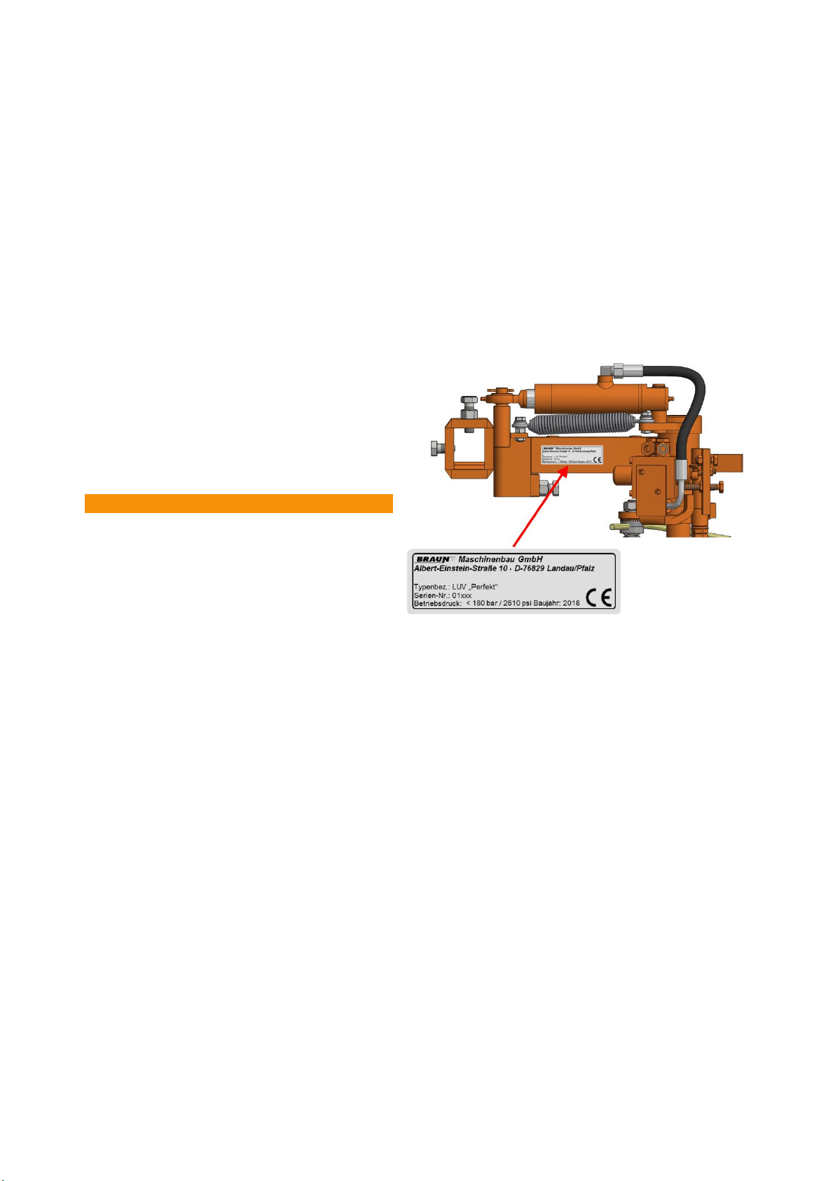
2.4 Type plate................................................................................................................................ 8
2.5 Protection class ....................................................................................................................... 8
3 Safety............................................................................................................................................... 9
3.1 Meaning of the warning information...................................................................................... 9
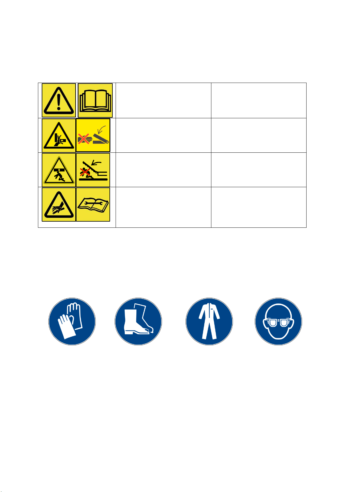
3.2 Warning signs on the unit ..................................................................................................... 10
3.3 Personal protective equipment............................................................................................. 10
3.4 Worker qualifications ............................................................................................................ 11
3.5 Safety instruction .................................................................................................................. 12
3.6 Appropriate use..................................................................................................................... 13
3.7 Traffic safety.......................................................................................................................... 13
3.8 Danger zone when in operation............................................................................................ 13
3.9 Obligation of the owner to exercise due care....................................................................... 14
3.10 Obligation of the user to exercise due care .......................................................................... 14
4 Before use...................................................................................................................................... 15
4.1 Installation............................................................................................................................. 15
4.1.1 Installation description LUV .......................................................................................... 15
4.2 Setting up/adjusting .............................................................................................................. 16
4.2.1 Feeler positions ............................................................................................................. 16
4.2.2 Crow's foot blade .......................................................................................................... 17
4.3 Storage and protection between periods of use................................................................... 17
4.4 Storage location for the operating manual ........................................................................... 17

3
5 Operation ...................................................................................................................................... 18
5.1 Safe operation / functioning ................................................................................................. 18
5.2 Work flows............................................................................................................................. 18
5.3 Operating information........................................................................................................... 18
5.3.1 Oil .................................................................................................................................. 18
5.3.2 Soil ................................................................................................................................. 18
6 Servicing and cleaning / customer ................................................................................................ 19
6.1 Safety measures .................................................................................................................... 19
6.2 Servicing by specialist technicians......................................................................................... 19
6.2.1 Blade bolt....................................................................................................................... 19
6.2.2 Threaded pin short multi-splined shaft......................................................................... 20
6.2.3 Lubrication..................................................................................................................... 20
7 Servicing and repair / BRAUN dealer............................................................................................. 21
7.1 Servicing cycles for safe operation........................................................................................ 21
7.1.1 LUV spring...................................................................................................................... 21
8 Transport and delivery .................................................................................................................. 23
8.1 Transport to the customer .................................................................................................... 23
8.1.1 Unpacking...................................................................................................................... 23
8.2 Dispose of the packaging safely ............................................................................................ 23
9 Faults and possible causes ............................................................................................................ 24
9.1 Frequently asked questions .................................................................................................. 24
9.1.1 LUV &Modular system................................................................................................... 24
9.1.2 LUV & soil ...................................................................................................................... 26
9.1.3 LUV –attachment. operation and maintenance........................................................... 26
9.2 Contact .................................................................................................................................. 29
10 List of spare parts ...................................................................................................................... 30
11 Dimensions LUV Perfekt ............................................................................................................ 35
12 Decommissioning, dismantling, disposal .................................................................................. 37

4
1 Identification
1.1 Declaration of conformity
Within the meaning of EU Directive 2006/42/EC
The manufacturer,
BRAUN Maschinenbau GmbH
Albert - Einstein - Strasse 10
D –76829 Landau i. d. Pfalz
Germany
hereby declares that the unit described below
Type of construction:
Year of
construction
:
Appropriate use:
Unit No.:
conforms with the stipulations of the standards listed below.
EN ISO 12100 - Safety of machinery - General principles for design - Risk
assessment and risk reduction
EN ISO13857 - Safety of machinery - Safety distances to prevent hazard
zones being reached by upper and lower limbs
DIN EN ISO 4413 [2] - Hydraulic fluid power - General rules and safety
requirements for systems and their components
EN 61310-2 - Safety of machinery: Indication, marking and actuation
EN 614-1 - Safety of machinery: Ergonomic design principles
EN 60204 - Safety of machinery: Electrical equipment of machines
EN ISO 4254 - Agricultural machinery - Safety
EN 349 (ISO 13854) - Safety of machinery: Minimum gaps to avoid crushing
of parts of the human body
This EC declaration of conformity loses its validity if
the unit is converted, modified or used for a different purpose
without our explicit prior written approval.
it is used contrary to the instructions in the operating manual.
Landau, 28/05/18
Place, Date
S. Braun, CEO
With overall responsibility

5
1.2 Target group
The unit is designed for ecological soil tilling. The use of chemicals can be reduced
by mechanical weed control.
1.3 Explanation / note
The unit may only be supplied together with an operating manual (to provide security
in legal terms).
1.4 Copyright
The unit has been designed and built to the state of the art of current technology by
BRAUN Maschinenbau GmbH. The manufacturer has the sole copyright for
marketing and exhibition. Any constructional changes to the unit and its accessory
parts require the prior written approval of BRAUN Maschinenbau GmbH.
If this stipulation is infringed then all liability by and claims under warranty from the
manufacturer shall be null and void!
All parts and components may be replaced solely by original parts and components
from BRAUN Maschinenbau GmbH!

6
2 Product description
2.1 Structure
Figure 1: LUV
11
1
3
7
10
8
9
2
4
5
6

7
2.2 Components and their functions
Item
COMPONENT
FUNCTION
1
Plug
12 V power supply for the remote control
2
Adjusting screw
Setting the control pressure at the pressure regulating
valve
3
LUV recess
Holder to attach the LUV to the tractor
4
Shaft holder
Holder for accessories (dimensions 50x25)
5
Feeler holder
Toothed disk to set the feeler position
6
Crow's foot blade
Tool to cut the roots of weeds between the rows of vines
7
Feeler
Sensing the plant
8
Feeler hoop
Lever to operate the control valve
9
Hydraulic
connection (P)
Hydraulic connection to the tractor, under pressure
10
Hydraulic
connection (T)
Tank connection, return flow to the tractor, not under
pressure
11
Remote control
For manual actuation of the LUV
2.3 Technical data
2.3.1 Performance and operating values
Min. drive rating
20 kW
Min. travelling speed
unlimited
Max. travelling speed
8 km/h
Max. working depth
150 mm
Oil supply
7 –12 l (one side) / 12 –24 l (both sides), max. 180
bar
2.3.2 Dimensions
(H x W x D) mm
Transport
590 x 180 x 460
Installation/working
590 x 430 (610) x 460
2.3.3 Weight
Transport weight
30 kg
Weight in use
28.8 kg

8
2.3.4 Sound pressure
Sound pressure of the tractor
2.3.5 Ambient conditions
not dependent on temperature
secure attachment of the peripherals and third party
devices to the tractor
2.3.6 Soil conditions
all normal types of soil can be worked
2.4 Type plate
The unit is identified by a type plate that
clearly identifies the unit concerned by the
type designation, serial number and year of
construction. The type plate is attached to
the rear side of the middle part of the LUV.
NOTE
Please have at hand all the relevant
details from the type plate for all
enquiries concerning this unit!
Figure 2: Position of the type plate
2.5 Protection class
All electrical connections are secured to IP 67.

9
3 Safety
The Safety section contains basic warning and working information. Following the
information given in this section is a basic prerequisite for safe working with the unit
and its safe operation. In addition, in the other sections of this operating manual there
is additional warning information that must likewise be followed. The warning
information is shown next to the relevant actions.
3.1 Meaning of the warning information
In this operating manual the warning information is shown in a systematic way
according to the severity of the danger and the probability of it occurring. The danger
signs bring to your attention any residual hazards that can be avoided for design
reasons when operating the unit.
The warning information that is given is structured as follows:
Example
DANGER
Type and source of the danger
Possible consequences if disregarded
Means to avoid the danger
Danger levels of the warning information
The danger level is indicated by the signal word. The danger levels are classified
into 4 levels as follows:
Fatal danger
DANGER
Type and source of the danger
Possible consequences if disregarded
Means to avoid the danger
Severe injury
WARNING
Type and source of the danger
Possible consequences if disregarded
Means to avoid the danger
Minor injury
CAUTION
Type and source of the danger
Possible consequences if disregarded
Means to avoid the danger
Damage to the unit
NOTE
Type and source of the danger
Possible consequences if disregarded
Means to avoid the danger
i

10
3.2 Warning signs on the unit
Never remove the warning signs from the unit. Replace any safety stickers and
information that are missing or illegible.
The following warning signs have been applied to the unit
The unit can be
dangerous. Treat
prudently and handle
with care.
Read the operating manual
all the way through before
using the unit for the first
time.
Never reach into areas
where there is a risk of
being crushed
Do not touch any moving
parts.
Do not crawl under the
installed unit / components.
Danger of injury
It is forbidden to stay in the
swivelling area of the unit
and attached parts.
Beware of escaping fluid
under high pressure.
Disable the high pressure
unit. Danger of injury
Follow the instructions given
in the operating manual.
Follow the corresponding
instructions when carrying
out maintenance!
3.3 Personal protective equipment
It is important to wear personal protective equipment when operating the unit.
Use work gloves that are secure against cutting and piercing, safety shoes, cut-
proof trousers and protective goggles when installing / deinstalling or when making
adjustments or performing maintenance or cleaning.

11
3.4 Worker qualifications
Only trained and suitably instructed persons may work with the crow’s foot
blade under-vine weeder (LUV). The unit may only be put into operation after
thoroughly studying all the sections of this operating manual by a suitably
qualified person who has been instructed and commissioned by the owner.
The responsibilities of the relevant persons for operation, setting up and
maintenance must be clearly defined.
Trainees may only work on the unit under the supervision of an experienced
person who has been authorised to give instruction.
Maintenance and servicing work may only be performed by especially trained
and qualified technicians. When doing so they must follow the details
concerning servicing and all the relevant safety rules and local regulations.
Persons
Activity
Instructed
person
Personal with
technical training
(authorised to give
instructions)
Superior with
the
corresponding
competence
Transport
X
X
X
Initial commissioning
X
X
Operation
X
X
X
Setting up/equipping
X
X
Tracking down faults
X
X
Correcting faults
X
X
Maintenance
X
X
Cleaning
X
X
X
Servicing
X
X
Disposal
X
X
X

12
The customer hereby confirms this with his signature,
1. that he has received in full and in good condition the operating manual that belongs to the unit.
2. that he has been instructed that the operating manual contains exceptionally important
information (especially safety information) and has received instruction on the residual risks.
3. that he has been instructed that the unit may only be started up after having carefully studied the
operating manual.
4. that he has been instructed that the unit may only be used by trained, instructed and qualified
persons.
5. that he has been instructed that compliance with the operating manual does not relieve him of
the obligation to comply with the relevant applicable laws and regulations, especially regarding
use outside the EU. This also applies if extended requirements must be implemented due to the
corresponding changes in the laws and regulations and due to leading decisions.
6. a signed copy of this declaration is to be sent to BRAUN Maschinenbau GmbH.
_________________ ___________ _______________________ _____________________
Place Date Name in capitals Signature of the customer
3.5 Safety instruction
This safety instruction is to be filled out by the BRAUN dealer for the final customer.
Customer
address
by the
manufacturer
BRAUN Maschinenbau
GmbH
Albert-Einstein-Strasse 10
D-76829 Landau i. d. Pfalz
Germany
Concerning
unit
Serial number: ________________________
Designation: ________________________
Year of construction: ________________________

13
3.6 Appropriate use
Safety in operation of the supplied unit can only be guaranteed if it is used
appropriately and correctly. Appropriate use includes following the operating
and instruction manual (also of the tractor) and carrying out all the maintenance
and servicing work. Attachments and equipment from other manufacturers may
only be used after consulting BRAUN Maschinenbau GmbH.
This unit has been designed solely for the usual soil tilling in vineyards and
orchards or in specialised cultivation.
Any form of use going beyond this is not appropriate!
BRAUN Maschinenbau GmbH shall have no liability whatsoever for any
damage caused as a result, the user/owner bears the sole risk in such cases.
The relevant applicable accident prevention and health and safety at work
regulations and other generally recognised safety, occupational medicine and
road traffic rules are to be complied with.
3.7 Traffic safety
When travelling on public roads and streets the tractor must comply with the
road traffic regulations of the relevant country when this unit is attached to it.
The vehicle holder and tractor driver are responsible for compliance with these
regulations.
3.8 Danger zone when in operation
Never allow anybody to get into or stay in the danger zone!
If you get between the tractor and the unit there is a great and possibly fatal
danger from the tractor rolling away or from movements of the unit.
The following illustration shows the danger zones of the unit.
Figure 3: Danger zones of the unit

14
3.9 Obligation of the owner to exercise due care
The owner undertakes to use the unit only when it is in flawless condition. He must
check its condition before use and ensure that any faults are corrected before starting
it up.
The owner undertakes only to have persons working on or with the unit who:
have been taught the basic principles of safety at work and accident
prevention and instructed in the handling of the unit.
have read and understood the Safety section and the warning information in
this operating manual and have confirmed this with their signature.
who are wearing the required and stipulated personal protective equipment
(work clothing, safety shoes, protective gloves, safety goggles, ear
protection. etc.) and also to check this.
3.10 Obligation of the user to exercise due care
The operator must have read and understood the operating manual.
Only trained and instructed persons are permitted to operate the unit.

15
4 Before use
4.1 Installation
4.1.1 Installation description LUV
WARNING
The LUV can fall over
Your lower limbs could be crushed
Wear safety shoes
Handle heavy loads with lifting gear
Component
Installation steps
1. Push the LUV recess onto the square 50 x 50
2. Push the LUV so that it is flush with the front
edge of the square
3. Insert the bolt (1)
4. Adjust and lock the adjusting bolts (2)
5. Firmly tighten up the bolt (1)
CAUTION
Slipping of the hydraulic couplings
Minor hand injuries
Wear safety shoes
Careful handling
Component
Assembly steps
1. Connect the hydraulic coupling (1) pressure
hose (control block marking P) to the control unit
of the tractor
2. Connect the hydraulic coupling (2) pressure
hose (control block marking T) to the
unpressurised return line of the tractor
3. Plug the square tube of the remote control into
the requisite holder and screw it up tight
4. Connect the 12 V plug (4) to the electrical
system of the tractor
2
1
2
4
1
3

16
4.2 Setting up/adjusting
4.1.2 Feeler positions
Component
Adjustment steps
1. Align the feeler so that it is parallel
to the ground (red marking)
Ensure a 90° angle!
2. When operating the feeler up to the
détente stop of the control valve
this must be flush with the front
edge of the crow's foot blade
NOTE
Depending on the requirements, the feeler can be set to be minimally in front of the blade to create a
buffer zone
Component
Adjustment steps
1. Feeler position [1]
Vines growing straight
Push the feeler, without turning the toothed
wheels,
(in the hole of the toothed disk pair) further to
the front (with respect to the plant) to create a
buffer zone
2. Feeler position [1`]
Steep slopes
Turn the feeler at the feeler hoop to the front (to
the right, counterclockwise, to the left,
clockwise) by means of the fine teeth of the
toothed disk pair to increase the distance
B`between blade and sensor
3. Travelling speed [B]
Reaction time
Push the feeler further into the bolt holder to
swivel more quickly under the row of vines
NOTE
Feeler position [1]
The feeling setting with parameters A and B is intended for vineyards / orchards on flat terrain.
Distance A with respect to A´. is increased. This buffer zone represents an additional protective
element for the plants. The LUV unit can be initiated earlier by earlier and longer contact between
feeler and plant. The result is that the weeding area around the plants is reduced and the safety
clearance is increased.
Feeler position [1`]
For steep slopes or problem areas (with plants that grow irregularly or not straight) the feeler at the
feeler hoop can be turned to the front (to the right, counter clockwise, to the left, clockwise) by means
of the fine teeth of the toothed disk pair. The distance B` between blade and feeler is increased as a
result so that the blade swivels inwards earlier before the vine with the aid of the feeler.
Travelling speed
The higher the speed of the tractor, the further the feeler must be pushed into the bolt holder
(reduction of distance A) so as to swivel more quickly to back under the row of vines after initiating.
In the same way, when travelling slowly, the feeler must be pushed more out of the bolt holder
(increase of distance A A´) so that the blade does not swivel into the row of vibes too quickly.
90°
parallel to the
ground
Direction of
travel
Vine

17
4.1.3 Crow's foot blade
Component
Adjustment steps
1. Rotate the crow's foot blade itself by 25° (2 teeth) to the
rear (away from the plant)
(The illustration shows the working position)
NOTE
The feeler of the LUV Perfekt with crow's foot blade is built in a similar way to that of a conventional
crow's foot blade. The earth that had been heaped up between the vines can be ploughed out with the
crow's foot blade.
4.2 Storage and protection between periods of use
Store the unit so that it is cool and dry. Protect it against the direct rays of the sun.
Clean and lubricate the unit if it is to be stored for a longer period of time.
4.3 Storage location for the operating manual
The operating manual must be readily available to hand for the user at all times.

18
5 Operation
5.1 Safe operation / functioning
Do not operate the unit without a vehicle (tractor). Follow the operating manual of the
relevant tractor.
DANGER
Running over persons
Death or severe injury
Never allow anybody to get into or stay in the danger zone
Ensure that nobody is in the danger zone of the unit (see section 3.8).
If any persons get into the danger zone of the unit, stop the tractor at once.
5.2 Work flows
NOTE
Resistance of the soil is too great
Blade or other component can break
Only let the blade into the ground while in motion
The LUV may only be lowered into the ground in the row while in motion.
Next, turn on the oil supply of the LUV.
5.3 Operating information
5.3.1 Oil
The LUV unit and all the hydraulic components are not suitable for use with bio-oil!
5.3.2 Soil
The LUV unit can be used in all the usual types of soil, but less good working results
can be expected in very stony soil, unless it is pre-treated. Here we recommend that
the soil should be prepared beforehand with a suitable device. Around 5-10 cm
should always be ploughed up to achieve the best results. It is easier to distinguish
weeds as a result and there is less formation of islands of grass.
Figure 4 Ploughed-up ground
i

19
6 Servicing and cleaning / customer
6.1 Safety measures
The operator must clean any dirt off the unit
oRough cleaning, grass, etc.
The operator must lubricate the unit
CAUTION
Sharp edges
Cuts on the hands
Wear protective gloves
Use a suitable tool for cleaning
6.2 Servicing by specialist technicians
6.2.1 Blade bolt
Check the blade bolt:
each time before starting work.
before using for the first time.
one hour after using for the first time.
depending on the intensity of the work and the soil properties.
Figure 5: Blade bolt
Item
Designation
Spare part No.
1
Blade shaft
001481/0014811
2
Toothed disk to blade shaft
Upper part: 208011
Pair: 208013
3
Blades
Crow's foot blade toothed disk 350 mm: 00125151/00121511
Crow's foot blade toothed disk 350 mm: 001146/01147
Crow's foot blade toothed disk 500 mm: 001211301/001211311
4
Blade bolt
M16x50 10.9 101165021
5
Wedge locking screw
20517201
6
Toothed disk to blade shaft
208012
NOTE
Blade bolt can become loose
Toothed disk worn
Tighten up blade bolt to 300 Nm
5
6
2
1
3
4
i

20
6.2.2 Threaded pin short multi-splined shaft
Checking the threaded pin:
each time before starting work.
before using for the first time.
one hour after using for the first time.
depending on the intensity of the work and the soil properties.
NOTE
Threaded pin can become loose
Multi-splined profile of the weed blade shaft is damaged
Tool can become loose
Tighten up the threaded pin to 35 Nm and lock in place
Component
Adjustment steps
1. Position the threaded pin (1) in the groove
(Ensure that the threaded pin engages into
the groove)
2. Tighten up the threaded pin (1) to 35 Nm
3. Lock with the hexagonal nut (2)
Item
Designation
Spare part No.
1
Threaded pin
126122000
2
Hexagonal nut
15012101
6.2.3 Lubrication
NOTE
Components run dry
Bearing points worn
Regularly ensure lubrication
Component
Lubrication steps
1. Lubricate the following lubrication points with acid-
free industrial every 50 hours of operation:
(1) Cylinder eye
(2) Feeler shaft
(3) Central LUV shaft
(4) Cylinder housing
i
i
1
4
3
2
1
2
Table of contents
Other Braun Farm Equipment manuals
Popular Farm Equipment manuals by other brands

Repossi
Repossi RA RAKE 12+12 VS User and maintenance manual

paladin
paladin 1A-MT113PE instruction manual

MacDon
MacDon D1 Series Unloading and assembly instructions

Urban Coop Company
Urban Coop Company Round-Top Mobile Chicken Coop Assembly instructions

RO Bucket
RO Bucket RB5 User instructions

HighLine
HighLine BM1400 operating manual