Demco 650 SS User manual

AG20046, Rev 2
02/19
GRAVITY FLOW WAGON
500 SS, 650 SS & 750 SS

Page 2 AG20046
GENERAL INFORMATION
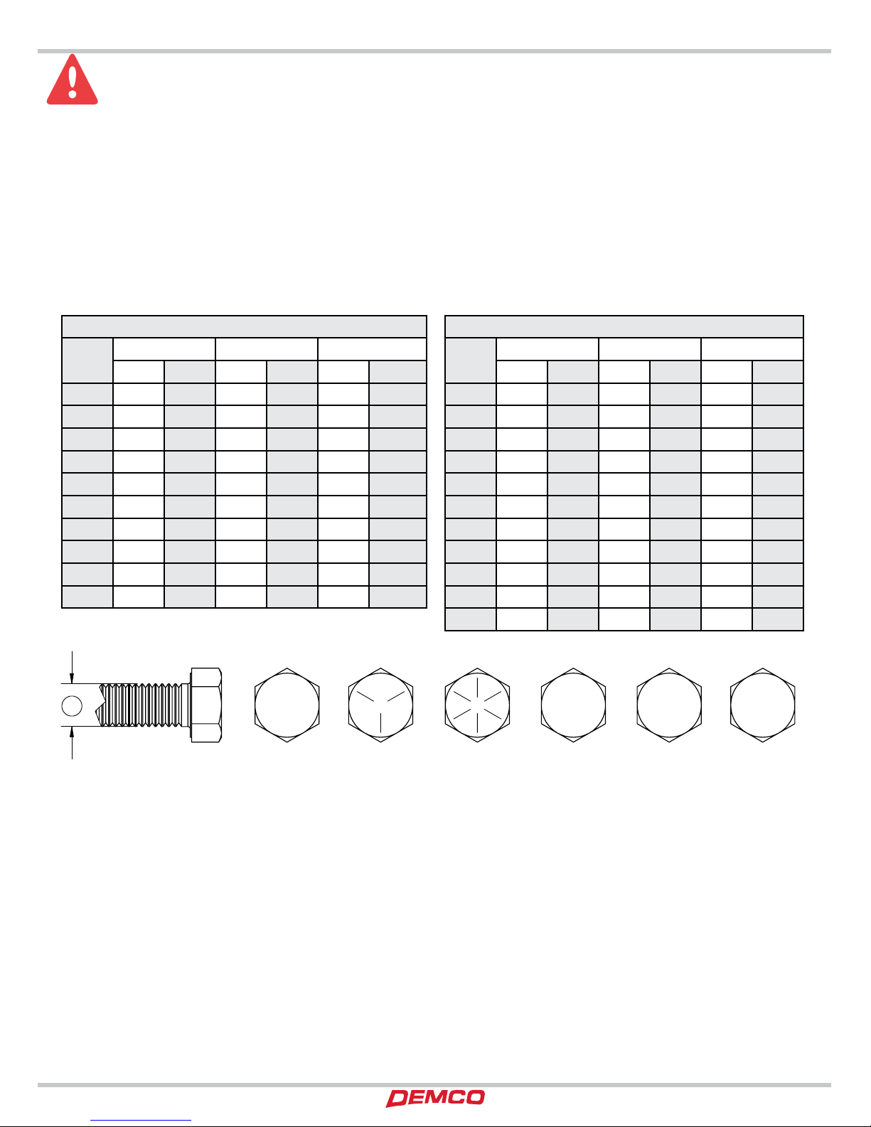
1. Unless otherwise specified, high-strength (grade5)
(3 radial-line head markings) hex head bolts are used
throughout assembly of this piece of equipment.
2. Whenever terms “LEFT” and “RIGHT” are used in this
manual it means from a position behind wagon box
and facing forward.
3. When placing a parts order, refer to this manual for
proper part numbers and place order by PART NO. and
DESCRIPTION.
4. Read assembly instructions carefully. Study
assembly procedures and all illustrations before you
begin assembly. Note which parts are used in each
step. This unit must be assembled in proper sequence
or complications will result.
WARNING: TO AVOID PERSONAL INJURY OR DEATH, OBSERVE FOLLOWING
INSTRUCTIONS:
Never overload wagon. Do not exceed the rating of the gear or load rating of the tires,
whichever is less.
Ensure that anybody present is clear before applying power to any machinery used in
conjunction with wagon box or when moving box.
Never allow anyone in, near, or on gravity box during transporting or unloading of grain.
Moving grain is dangerous and can cause entrapment, resulting in severe injury or death
by suffocation.
Do not exceed 20 miles per hour when towing wagon.
Thank you for purchasing a Demco Gravity Flow Wagon. We feel you have made a wise choice and hope you are
completely satisfied with your new piece of equipment. Proper care and use will result in many years of service.
SIGNAL WORDS:
WARRANTY POLICY, OPERATOR MANUALS & REGISTRATION
Go online to www.demco-products.com to review Demco warranty policies, operator manuals and register your Demco
product.
General Information & Table of Contents ............................................................................... 2
Safety, Signal Words .................................................................................................................. 3
Equipment Safety Guidelines, Lighting and Marking............................................................ 4
Safety Sign Care ......................................................................................................................... 4
Tire Safety.................................................................................................................................... 5
Before Operation ....................................................................................................................... 5
During Operation......................................................................................................................5-6
Following Operation.................................................................................................................. 6
Highway and Transport Operations........................................................................................6-7
Performing Maintenance........................................................................................................... 7
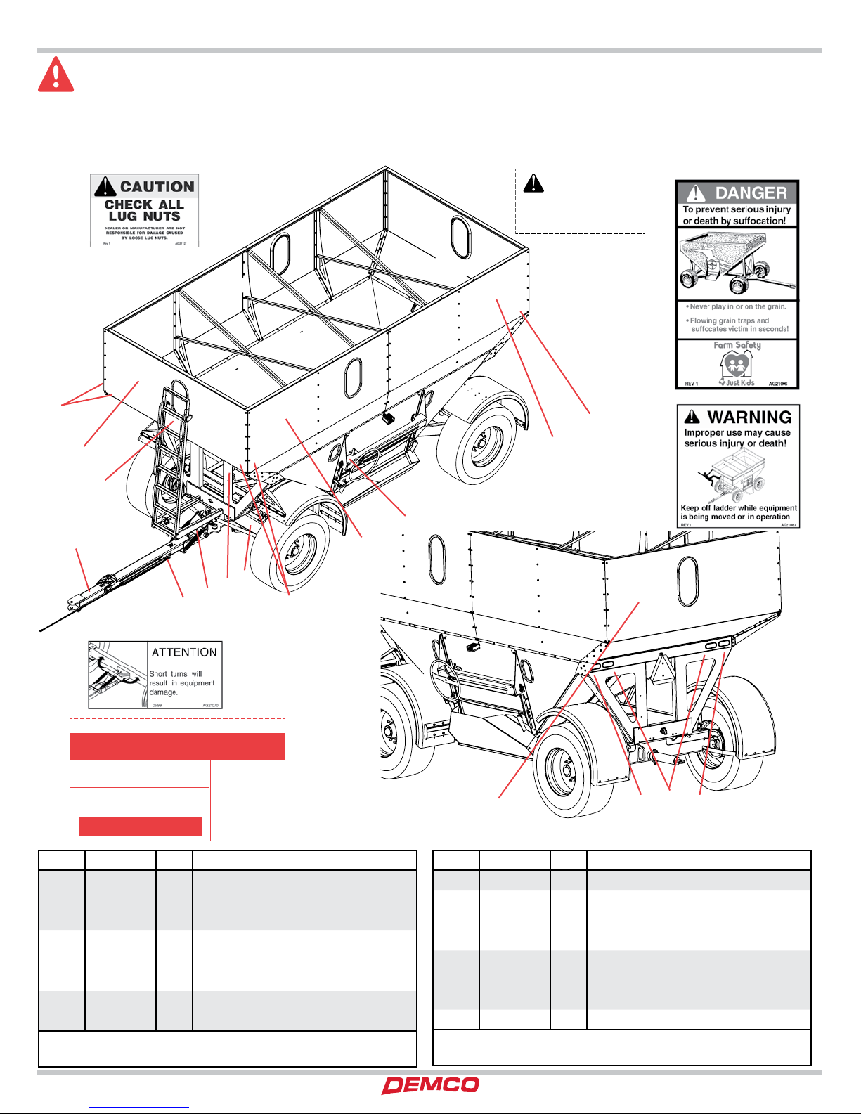
Safety Sign Locations................................................................................................................. 8
Bolt Torque.................................................................................................................................. 9
Running Gear Parts Breakdown............................................................................................ 10-11
Brake Tongue Maintenance and Adjustment ........................................................................ 12
Brake Tongue Parts Breakdown .............................................................................................. 13
13” Brake Cluster Parts Breakdown......................................................................................... 14
Running Gear Brake Line Parts Breakdown ........................................................................... 15
Brake System Maintenance and Repair............................................................................... 16-17
500 Gravity Flow Box Parts Breakdown............................................................................... 18-19
650 Gravity Flow Box Parts Breakdown............................................................................... 20-21
750 Gravity Flow Box Parts Breakdown............................................................................... 22-23
Door Lift & Chute Parts Breakdown ........................................................................................ 24
Gravity Box to Running Gear Parts Breakdown ..................................................................... 25
Gravity Flow Lighting & SMV Parts Breakdown ..................................................................... 26
Fender Parts Breakdown .......................................................................................................... 27
Maintenance and General Operation..................................................................................... 28
INTRODUCTION
TABLE OF CONTENTS

AG20046 Page 3
TAKE NOTE! THIS SAFETY ALERT SYMBOL FOUND THROUGHOUT THIS
MANUAL IS USED TO CALL YOUR ATTENTION TO INSTRUCTIONS INVOLVING
YOUR PERSONAL SAFETY AND SAFETY OF OTHERS. FAILURE TO FOLLOW THESE
INSTRUCTIONS CAN RESULT IN INJURY OR DEATH!
THIS SYMBOL MEANS
ATTENTION
BECOME ALERT
YOUR SAFETY IS INVOLVED!
DANGER:
Indicates an imminently hazardous situation that, if not
avoided, will result in death or serious injury. This signal
word is to be limited to most extreme situations typically
for machine components which, for functional purposes,
cannot be guarded.
WARNING:
Indicates a potentially hazardous situation that, if not
avoided, could result in death or serious injury, and includes
hazards that are exposed when guards are removed. It may
also be used to alert against unsafe practices.
CAUTION:
Indicates a potentially hazardous situation that, if not
avoided, may result in minor or moderate injury. It may also
be used to alert against unsafe practices.
If you have questions not answered in this manual, require additional copies, or if your manual is damaged, please contact
your dealer or Demco, 4010 320th Street, Boyden, IA 51234
ph: (712) 725-2311 or Toll Free: 1-800-543-3626 Fax: (712) 725-2380
http://www.demco-products.com
SIGNAL WORDS:
This manual uses the following signal words--DANGER,
WARNING, and CAUTION-- with safety messages. The
appropriate signal word has been selected using the
following guidelines.
SAFETY

Page 4 AG20046
SAFETY...YOU CAN LIVE WITH IT
EQUIPMENT SAFETY GUIDELINES
Every year many accidents occur which could have been avoided by a few seconds of thought and a more careful
approach to handling equipment.You, the operator, can avoid many accidents by observing the following precautions
in this section. To avoid personal injury, study the following precautions and insist those working with you, or you
yourself, follow them.
In order to provide a better view, certain illustrations in your owners manual may show an assembly with a safety shield
removed. However, equipment should never be operated in this condition. Keep all shields in place. If shield removal
becomes necessary for repairs, replace shield prior to use.
Replace any caution, warning, danger or instruction safety decal that is not readable or is missing.
Do not attempt to operate this equipment under the influence of alcohol or drugs.
Review safety instructions with all users annually.
Operator should be a responsible adult. DO NOT ALLOW PERSONS TO OPERATE OR ASSEMBLE THIS UNIT UNTIL
THEY HAVE DEVELOPED A THOROUGH UNDERSTANDING OF SAFETY PRECAUTIONS AND HOW IT WORKS.
To prevent injury or death, use a tractor equipped with a roll over protective system (ROPS). Do not paint over, remove,
or deface any safety signs or warning decals on your equipment. Observe all safety signs and practice instructions
on them.
Never exceed limits of a piece of machinery. If its ability to do a job, or to do so safely is in question DON’T TRY IT.
LIGHTING AND MARKING
It is the responsibility of customer to know lighting and marking requirements of local highway authorities and to
install and maintain equipment to provide compliance with regulations. Add extra lights when transporting at night
or during periods of limited visibility.
Lighting kits are available from your dealer or from manufacturer.
REMEMBER
Your best assurance against accidents is a careful and responsible operator. If there is any portion of this manual or
function you do not understand, contact your local authorized dealer or manufacturer.
SAFETY SIGN CARE
• Keepsafetysignscleanandlegibleatalltimes.
• Replacesafetysignsthataremissingorhavebecomeillegible.
• Replacementpartsthatdisplayedasafetysignshouldalsodisplaycurrentsign.
• Safetysignsareavailablefromyourdistributor,dealerpartsdepartment,orfactory.
How to install safety signs:
• Besurethatinstallationareaiscleananddry.
• Decideonexactpositionbeforeyouremovebackingpaper.
• Removesmallestportionofsplitbackingpaper.
• Aligndecaloverspeciedareaandcarefullypresssmallportionwithexposedstickybackinginplace.
• Slowlypeelbackremainingpaperandcarefullysmoothremainingportionofdecalintoplace.
• Smallairpocketscanbepiercedwithapinandsmoothedoutusingpieceofdecalbackingpaper.
SAFETY

AG20046 Page 5
TIRE SAFETY
• Failuretofollowproperprocedureswhenmountingatireonarimcanproduceanexplosionwhichmayresultina
serious injury or death.
• Donotattempttomountatireunlessyouhaveproperequipmentandexperiencetodojob.
• Inatingorservicingtirescanbedangerous.Wheneverpossible,trainedpersonnelshouldbecalledtoserviceand/
or mount tires.
• Alwaysorderandinstalltiresandwheelswithappropriatetypeandloadcapacitytomeetorexceedanticipated
weight to be placed on the equipment.
• Referto“TIREINFLATIONDECAL”inyourownersmanualandonthefrontbolstertubeformaximumtirepressure
for a Demco Grain Wagon.
BEFORE OPERATION
• CarefullystudyandunderstandthismanualandtheOwner’sManual.
• Donotwearloose-ttingclothingwhichmaycatchinmovingparts.
• Alwayswearprotectiveclothingandsubstantialshoes.
• Itisrecommendedthatsuitableprotectivehearingandeyeprotectionbeworn.
• Operatormaycomeincontactwithcertainmaterialswhichmayrequirespecicsafetyequipmentrelativetohandling
of such materials. (Examples: extremely dusty, molds, fungus, bulk fertilizers, etc.)
• Keepwheelandlugnutstightenedtospeciedtorque.
• Assurethatagriculturalimplementtiresareinatedevenly.
• Giveunitavisualinspectionforanyloosebolts,wornparts,orcrackedwelds,andmakenecessaryrepairs.Follow
maintenance safety instructions included in this manual.
• Besuretherearenotoolslyingonorinequipment
• Donotuseunituntilyouaresurethatareaisclear,especiallyaroundchildrenandanimals.
• Don’thurrylearningprocessortakeunitforgranted.Easeintoitandbecomefamiliarwithyournewequipment.
• Practiceoperationofyourequipmentanditsattachments.Completelyfamiliarizeyourselfandotheroperatorswith
its operation before using.
• Makesurethatbrakesareevenlyadjusted(ifequippedwithbrakes)
• UseatractorequippedwithRollOverProtectionSystem(ROPS) andfastenyour seatbeltpriortostartingthe
engine.
• ManufacturerdoesnotrecommendusageofatractorwiththeROPSremoved.
• Movetractorwheelstowidestrecommendedsettingstoincreasestability.
• Donotallowanyonetostandbetweentongueorhitchandtowingvehiclewhenbackinguptoequipment.
DURING OPERATION
• Bewareofbystanders,PARTICULARLYCHILDREN!Alwayslookaroundtomakesurethatitissafetostart
engine of towing vehicle or move unit. This is particularly important with higher noise levels and quiet cabs, as
you may not hear people shouting.
• NOPASSENGERSALLOWED-Donotcarrypassengersanywhereonorintractororequipment.
• Keephandsandclothingclearofmovingparts.
• Donotclean,lubricate,oradjustyourequipmentwhileitismoving.
SAFETY

Page 6 AG20046
• Whenhaltingoperation,evenperiodically,settractorortowingvehiclesbrakes,disengagePTO,shutoffengine,
and remove ignition key.
• Beespeciallyobservantofoperatingareaandterrain.Watchforholes,rocks,orotherhiddenhazards.Always
inspect area prior to operation.
- DO NOT operate near edge of drop-off or banks.
- DO NOT operate on steep slopes as overturn may result.
- Operate up and down (not across) intermediate slopes. Avoid sudden starts and stops.
• Pickthemostlevelpossibleroutewhentransportingacrosselds.Avoidedgesofditches,gullies,andsteep
hillsides.
• Beextracarefulwhenworkingoninclines.
• Maneuvertractorortowingvehicleatsafespeeds.
• Avoidoverheadwiresorotherobstacles.Contactwithoverheadlinescouldcauseseriousinjuryordeath.
• Avoidloosegravel,rocks,andholes;theycanbedangerousforequipmentoperationormovement.
• Allowforunitlengthwhenmakingturns.
• Donotwalkorworkunderraisedcomponentsorattachmentsunlesssecurelypositionedandblocked.
• Keepallbystanders,pets,andlivestockclearofworkarea.
• Operatetowingvehiclefromoperatorsseatonly.
• Neverstandalongsideofunitwithenginerunningorattempttostartengineand/oroperatemachinewhile
standing alongside of unit.
• Neverleaverunningequipmentunattended.
• Asaprecaution,alwaysrecheckhardwareonequipmentfollowingevery100hoursofoperation.Correctall
problems. Follow maintenance safety procedures.
FOLLOWING OPERATION
• Followingoperation,orwhenunhitching,stoptractorortowingvehicle,setbrakes,shutoffengineandremove
ignition key.
• Storeunitinanareaawayfromhumanactivity.
• Donotparkequipmentwhereitwillbeexposedtolivestockforlongperiodsoftime.Damageandlivestockinjury
could result.
• Donotpermitchildrentoplayonoraroundstoredunit.
• Makesureallparkedmachinesareonahard,levelsurfaceandengageallsafetydevices.
• Wheelchocksmaybeneededtopreventunitfromrolling.
HIGHWAY AND TRANSPORT OPERATIONS
• SAFETYCHAINS:Ifequipmentisgoingtobetransportedonapublichighway,alwaysfollowstateandlocal
regulations regarding safety chains and auxiliary lighting. Be sure to check with local law enforcement agencies
for your own particular regulations. Only safety chains (not elastic or nylon/plastic tow straps) should be used
to retain connection between towing and towed machines in event of separation of primary attaching system.
Use a high strength, appropriately sized hitch pin with a mechanical retainer and attach safety chains. Criss cross
chains under tongue and secure to draw bar cage, mounting loops, or bumper frame.
• Adoptsafedrivingpractices:
- Keep brake pedals latched together at all times. NEVER USE INDEPENDENT BRAKING WITH MACHINE
IN TOW, LOSS OF CONTROL AND/OR UPSET OF UNIT CAN RESULT.
- Always drive at a safe speed relative to local conditions, ensure that your speed is low enough for an
emergency stop. Keep speed to a minimum.
- Reduce speed prior to turns to avoid risk of overturning.
SAFETY

AG20046 Page 7
- Always keep tractor or towing vehicle in gear to provide engine braking when going downhill. Do not coast.
- Donotdrinkanddrive!
• Complywithstateandlocallawsgoverninghighwaysafetyandmovementoffarmmachineryonpublicroads.
• Useapprovedaccessorylighting,agsandnecessarywarningdevicestoprotectoperatorsofothervehicleson
highway during transport. Various safety lights and devices are available from your dealer.
• Useofashingamberlightsisacceptableinmostlocalities.However,somelocalitiesprohibittheiruse.Local
laws should be checked for all highway lighting and marking requirements.
• Whendrivingtractorandequipmentonroadunder20m.p.h.(40kph)atnightorduringday,useashing
amber warning lights and a slow moving vehicle (SMV) identification emblem.
• Planyourroutetoavoidheavytrafc.
• Beasafeandcourteousdriver.Alwaysyieldtooncomingtrafcinallsituations,includingnarrowbridges,
intersections, etc.
• Beobservantofbridgeloadratings.Donotcrossbridgesratedlowerthangrossweightatwhichyouare
operating.
• Watchforobstructionsoverheadandsidetosidewhiletransporting.
• Alwaysoperateequipmentinapositiontoprovidemaximumvisibility.Makeallowancesforincreasedlength
and weight of equipment when making turns, stopping unit, etc.
PERFORMING MAINTENANCE
• Goodmaintenanceisyourresponsibility.Poormaintenanceisaninvitationtotrouble.
• Makesurethereisplentyofventilation.Neveroperateengineoftowingvehicleinaclosedbuilding.Exhaustfumes
may cause asphyxiation.
• Beforeworkingonthismachine,stoptowingvehicle,setbrakes,shutoffengineandremoveignitionkey.
• Alwaysusesafetysupportandblockwheels.Neveruseajacktosupportmachine.
• Alwaysusepropertoolsorequipmentforjobathand.
• Useextremecautionwhenmakingadjustments.
• Followtorquechartinownersmanualwhentighteningboltsandnuts.
• Neveruseyourhandstolocateahydraulicleakonattachments.Useasmallpieceofcardboardorwood.Hydraulic
fluid escaping under pressure can penetrate skin.
• Openingsinskinandminorcutsaresusceptibletoinfectionfromhydraulicuid.
Without immediate medical treatment, serious infection and reactions can occur.
• Whendisconnectinghydrauliclines,shutoffhydraulicsupplyandrelieveallhydraulicpressure.
• Replaceallshieldsandguardsafterservicingandbeforemoving.
• Afterservicing,besurealltools,partsandserviceequipmentareremoved.
• Donotallowgreaseoroiltobuilduponanystepsorplatform.
• Whenreplacingbolts,refertoownersmanual.
• Refertobolttorquechartinownersmanualforheadidenticationmarking.
• Wherereplacementpartsarenecessaryforperiodicmaintenance andservicing,genuinefactoryreplacement
parts must be used to restore your equipment to original specifications. Manufacturer will not claim responsibility
for use of unapproved parts or accessories and other damages as a result of their use.
• Ifequipmenthasbeenalteredinanywayfromoriginaldesign,manufacturerdoesnotacceptanyliabilityforinjury
or warranty.
• A re extinguisher and rst aid kit should be keptreadilyaccessible while performing maintenance on this
equipment
SAFETY

Page 8 AG20046
SAFETY SIGN LOCATIONS
Types of safety sign and locations on equipment are shown in illustration below. Good safety requires that you
familiarize yourself with various safety signs, type of warning, and area or particular function related to that area, that
requires your SAFETY AWARENESS.
CAUTION!
Do not exceed 20 MPH
when loaded.
09/99 AG2 1002
56
4
8
9
7
NOTICE!
Keep wheel lug nuts or bolts tightened to specified torque
IMPORTANT:
Always retorque wheels after first trip!
CAUTION:
Over inflation may result in damage to
running gear and box integrity.
REV 5 AG21001
650/750bu.
3/4”-16UNF Grade 8
T o rque to 400 ft. lbs.
450/550bu.
5/8”-18UNF Grade 8
T o rque to 225 ft. lbs.
Check tire pressure regularly .
365bu.
5/8”-18UNF Grade 5
T o rque to 150 ft. lbs.
Nut or Bolt T o rques
Tire Pressure for all 365/450/550/650/750
Bushel Gravity Flow W a gons
60 psi.
ITEM PART # QTY DESCRIPTION
1AA21071 2 REFLECTOR RED 2 X 9
2AA21072 6 REFLECTOR YELLOW 2 X 9
3AA21073 2 NONREFLECTIVE ORANGE 2 X 9
4AG21001 1 TIRE PRESSURE AND TORQUE RATING
5AG21002 1 CAUTION 20 M.P.H.
6AG21006 1 WAGON SAFETY
7AG21067 1 KEEP OFF LADDER
8AG21070 1 ATTENTION DO NOT TURN SHARP
Please order replacement parts by PART NO. and DESCRIP-
TION
ITEM PART # QTY DESCRIPTION
9AG21127 2 CHECK ALL WHEEL NUTS
10 AG21207 2 500 SS
-AG21208 2 650 SS
-AG21209 2 750 SS
11 AG21221 1 STRIPING REFLECTIVE- (PER FOOT)
12 DE21018 2 DEMCO LARGE
13 DE21017 2 DEMCO MEDIUM
14 BH21003 1 BRAKE LEVER INDICATOR
Please order replacement parts by PART NO. and DESCRIP-
TION
5
8
13
2
7
2
9
12
10
2
9
14 6
3
13 1
1
SAFETY

AG20046 Page 9
TORQUE WHEEL NUTS TO 400 ft/lbs (10 BOLT)
LUG NUTTORQUE
BOLT TORQUE
TORQUE SPECIFICATION
Torque figures indicated are valid for non-greased or non-oiled threads and heads unless otherwise specified. Therefore, do not grease or oil
bolts or capscrews unless otherwise specified in this manual. When using locking elements, increase torque values by 5%.
* GRADE or CLASS value for bolts and capscrews are identified by their head markings.
BOLT TORQUE DATA FOR STANDARD NUTS, BOLTS, AND CAPSCREWS
Tighten all bolts to torques specified in chart unless otherwise noted. Check tightness of bolts periodically, using bolt chart as guide.
Replace hardware with same grade bolt.
NOTE: Unless otherwise specified, high-strength Grade 5 hex bolts are used throughout assembly of equipment.
*5$'(
&/$66
&/$66
*5$'( *5$'(
&/$66
$
Bolt Torque for Standard bolts *
“A” GRADE 2 GRADE 5 GRADE 8
lb-ft (N.m) lb-ft (N.m) lb-ft (N.m)
1/4” 6 (8) 9 (12) 12 (16)
5/16” 10 (13) 18 (25) 25 (35)
3/8” 20 (27) 30 (40) 45 (60)
7/16” 30 (40) 50 (70) 80 (110)
1/2” 45 (60) 75 (100) 115 (155)
9/16” 70 (95) 115 (155) 165 (220)
5/8” 95 (130) 150 (200) 225 (300)
3/4” 165 (225) 290 (390) 400 (540)
7/8” 170 (230) 420 (570) 650 (880)
1” 225 (300) 630 (850) 970 (1310)
Bolt Torque for Metric bolts *
“A” CLASS 8.8 CLASS 9.8 CLASS 10.9
lb-ft (N.m) lb-ft (N.m) lb-ft (N.m)
6 9 (13) 10 (14) 13 (17)
7 15 (21) 18 (24) 21 (29)
8 23 (31) 25 (34) 31 (42)
10 45 (61) 50 (68) 61 (83)
12 78 (106) 88 (118) 106 (144)
14 125 (169) 140 (189) 170 (230)
16 194 (263) 216 (293) 263 (357)
18 268 (363) -- -- 364 (493)
20 378 (513) -- -- 515 (689)
22 516 (699) -- -- 702 (952)
24 654 (886) -- -- 890 (1206)

Page 10 AG20046
$
-
)
%
0
&
'
(
*
+
,
/
.
,7(0
3$57 '(6&5,37,21
47<
187+(;1&
/2&.:$6+(5
)/$7:$6+(5
%2/71&;*5+(;
/,)7$66,67635,1*
:$6+(5)/$7
1871&-$05,*+7+$1'
%2/71&;)8//7+5($'*5
+(;
%2/71&;*5
+(;18781)
6(76&5(:1&;62&.(7&83
32,17
[&277(53,1
721*8(07*3,1
%2/71&;*5+(;
5($&+3,3(&2//$5
%2/71);*5+(;
1871&1</21/2&.
1&1</21,16(57/2&.187
=(5.*5($6(81)6)
%2/71&;*5+(;
%2/71);*5+(;
=(5.137*5($6('(*5((
%5$.('580)+8%
7+5867%($5,1*
3,927$5002817,1*3,1
/()7%5$.(&/867(5URXJK
GUDZLQJ
5,*+7%5$.(&/867(5URXJK
GUDZLQJ
6(76&5(:1&;62&.(7
+($'
635,1*/,)7$66,673/$7(
)52176$)(7<&+$,1$1&+253,1
/%6$)(7<&+$,1
67((5,1*3,927$50
63,1'/(02817,1*3,1
/()7:+((/&$55,(5
5,*+7:+((/&$55,(5
5($5%2/67(5$66<
)5217%2/67(5
63,1'/(7215($5*($5
1871)+(;:6(76&5(:+2/(
+8%$66(0%/<*($5
7,(52'$66(0%/<
%5$.(721*8(
ADJUSTING THE LIFTASSISTSPRINGS
1. Raise the tongue and support on a stand.
2. Tighten the two 1/2” X 6” bolts equally to take out the slack
on the Lift Assist Springs .
3. Removethestandandadjustthetongueheightusing the two
1/2”x 6”bolts.Donotovertighten thespring. Overtightening
may stretch the spring causing permanent damage to the
spring.
ADJUSTING THETIE RODS FOR ALIGNMENT
Alignment is present at the factory. To check alignment, the
Tie Rods (P) should be adjusted to have 1/4” to 3/8” toe in
(measured at tire bead edge of rim). When this adjustment is
made, the tongue must be aligned with the round pipe on the
front bolster. Be sure both wheels toe in equally.
ADJUSTING THETURN STOPS
Adjustmentofthe5/8” x 2 1/2”bolts onthePivot Armshouldbe
set from the factory to not overturn. If adjustment is required
be careful that tires will not turn into the box frame.
NOTE: 500 BUSHEL DOES NOT
INCLUDE FRONT BRAKES
1. Tighten castle or slotted hex nut to initial torque indicated on
chart while turning hub in both directions to insure all bearing
surfaces are in contact.
2. Back nut off and repeat step #1.
3. Back nut off, do not allow hub to turn.
4. Tighten nut to final torque indicated on chart.
5. Install cotter pin, if needed loosen or tighten nut to the next
closest locking slot.
6. Check hub for end play.
7. If end play can be felt, start over and readjust bearings. If end
play is felt again, try readjusting with a different castle or slotted
hex nut.
8. The bearing are set correctly when no end play can be felt after
adjustment.
HUB INITIAL TORQUE FINAL TORQUE
10 BOLT 75 ft/lbs 50 ft/lbs
WHEELBEARING MAINTENANCE
TORQUE WHEEL NUTS TO 400 FT*LBS
REPLACEMENT PARTS AND MAINTENANCE
RUNNING GEAR PARTS BREAKDOWN

AG20046 Page 11
$
-
)
%
0
&
'
(
*
+
,
/
.
,7(0
3$57 '(6&5,37,21
47<
187+(;1&
/2&.:$6+(5
)/$7:$6+(5
%2/71&;*5+(;
/,)7$66,67635,1*
:$6+(5)/$7
1871&-$05,*+7+$1'
%2/71&;)8//7+5($'*5
+(;
%2/71&;*5
+(;18781)
6(76&5(:1&;62&.(7&83
32,17
[&277(53,1
721*8(07*3,1
%2/71&;*5+(;
5($&+3,3(&2//$5
%2/71);*5+(;
1871&1</21/2&.
1&1</21,16(57/2&.187
=(5.*5($6(81)6)
%2/71&;*5+(;
%2/71);*5+(;
=(5.137*5($6('(*5((
%5$.('580)+8%
7+5867%($5,1*
3,927$5002817,1*3,1
/()7%5$.(&/867(5URXJK
GUDZLQJ
5,*+7%5$.(&/867(5URXJK
GUDZLQJ
6(76&5(:1&;62&.(7
+($'
635,1*/,)7$66,673/$7(
)52176$)(7<&+$,1$1&+253,1
/%6$)(7<&+$,1
67((5,1*3,927$50
63,1'/(02817,1*3,1
/()7:+((/&$55,(5
5,*+7:+((/&$55,(5
5($5%2/67(5$66<
)5217%2/67(5
63,1'/(7215($5*($5
1871)+(;:6(76&5(:+2/(
+8%$66(0%/<*($5
7,(52'$66(0%/<
%5$.(721*8(
ITEM PART # DESCRIPTION QTY
100083 NUT .50NC HEX 2
200084 WASHER .50 LOCK 40
300085 WASHER .50 FLAT 2
400290 BOLT .625NC X 2.00 GR5 HEX 6
500306-30 LIFT ASSIST SPRING 2
600477 WASHER, FLAT, .625 2
700489 NUT .625NC JAM RIGHT HAND 4
800545 BOLT, .50NC X 6.00 FULL THREAD GR.5
HEX
900638 BOLT .75NC X 6.00 GR5 4
10 01922 NUT 1 1/2-12UNF HEX 2
11 01923 SET SCREW .25NC X .25 SOCKET 2
12 01935 3/16” x 2-1/2” COTTER PIN 2
13 01953-30 TONGUE MTG PIN 1
14 01964 BOLT .75NC X 7.00 GR5 HEX 1
15 01965-30 REACH PIPE COLLAR 1
16 02010 BOLT .50NF X 1.00 GR5 HEX 16
17 02587 NUT .625NC NYLON LOCK 3
18 02961 NUT .75NC NYLON LOCK 5
19 04642 ZERK, GREASE, .25 UNF SF 3
20 04835 BOLT .625NC X 9.00 GR5 HEX 1
21 05031 BOLT .50NF X 1.25 GR5 HEX 24
22 05395 ZERK, 1/8 NPT GREASE 45 DEGREE 1
23 07324 13” BRAKE DRUM F/871 HUB 4
24 07356 THRUST BEARING 2
25 07407-30 PIVOT ARM MOUNTING PIN 1
26 07910 LEFT 13” BRAKE CLUSTER 2
27 07911 RIGHT 13” BRAKE CLUSTER 2
Please order replacement parts by PART NO. and DESCRIPTION
ITEM PART # DESCRIPTION QTY
28 08097 SET SCREW .313NC X .50 2
29 09326-30 SPRING LIFT ASSIST PLATE 1
30 12127 FRONT SAFETY CHAIN ANCHOR PIN 1
31 12154 40,500 LB SAFETY CHAIN (NOT SHOWN) 1
32 16320-30 STEERING PIVOT ARM 1
-01951 BRONZE BUSHING REPLACEMENT 2
33 16324-30 SPINDLE MOUNTING PIN 2
34 16325-30 LEFT WHEEL CARRIER 1
-07355 BRONZE BUSHING REPLACEMENT 2
35 16326-30 RIGHT WHEEL CARRIER 1
-07355 BRONZE BUSHING REPLACEMENT 2
36 16327-30 REAR BOLSTER ASSY 650 & 500 1
-16322-30 REAR BOLSTER ASSY 750 1
37 16328-30 650 FRONT BOLSTER 1
-16330-30 500 FRONT BOLSTER 1
-16323-30 750 FRONT BOLSTER 1
-01951 BRONZE BUSHING REPLACEMENT 2
38 16329 SPINDLE, GEAR F/ 10 BOLT 4
39 16709 NUT 2.0” NF W/ SET SCREW 2
40 5474 HUB ASSEMBLY 10 BOLT 4
41 6067-30 TIE ROD ASSEMBLY, 1-1/4” 2
-6068 TIE ROD END W/ LEFT HAND THREADS
W/ JAM NUT
1
-6069 TIE ROD END W/ RIGHT HAND THREADS
W/ JAM NUT
1
42 6287 BRAKE TONGUE 650/750 1
-6286 BRAKE TONGUE 500 1
Please order replacement parts by PART NO. and DESCRIPTION
ITEM PART # DESCRIPTION QTY
40 5474-30 HUB ASSEMBLY 10 BOLT 1
A04305 BOLT .313 NC X .50 GR5 HEX 4
B*05088 1/4” X 2” COTTER PIN 1
C*07353 NUT 1.25-12 UNF CASTLE 1
D*07354 WASHER 1.25” FLAT 1
E07357 INNER CONE BEARING (39585) 1
F07358 OUTER CONE BEARING (460) 1
G07359 INNER CUP (39520) 1
H07360 OUTER CUP (453A) 1
I07361 OIL SEAL (CR30087) 1
J07362 HUB CAP 1
K07435 NUT .75 FLANGED WHEEL 10
L07861 BOLT .75” -16 UNF STUD 10
M09532 GASKET 1
Please order replacement parts by PART NO. and DESCRIPTION
* NOT INCLUDED WITH 5474-30
REPLACEMENT PARTS AND MAINTENANCE

Page 12 AG20046
Do Not Disassemble or Attempt to Adjust
The Tongue Push-Plate Assembly (34)
The braketongue is assembled and adjusted atthe factory: If
the tongue needs to be reassembled for any reason below is
a list of setting to follow:
A. Thepush-off assemblywithsprings shouldbeadjusted via
the adjustment spud on the rear half of the assembly. The
two springs need to be compress to 6-1/2”.
B. The front adjustment spudon the push-off assembly needs
tobe adjusted afterthe male tongue insert is in place and
latched in position. Pull the tongue forward against the
latch and adjust the spud until there is a 3/16” gap
for 650/750 and 7/16” gap for 500 between spud and
rear stop surface of male tongue.
C. Connect and tighten all brake lines. Fill the Master
Cylinder with DOT 3 or 4 brake fluid. CHECK FOR
ANY LEAKS.
Review all of the following instructions before installation and use of the hydraulic brake tongue.
Dealers or Distributors must review these instructions with the ultimate user. Failure to follow these instructions,
or failure to properly maintain the braking system after installation, can result in loss of braking action which could
cause severe property damage, personal injury and/or death.
MAINTENANCE
1. Frequently check the brake fluid level. (Fluid must be approved,
clean and uncontaminated.)
2. Inspect the brake tongue and brakes and replace bent, worn or
damaged parts.
3. Be constantly aware of the system’s braking quality and make
periodic checks. Consult a certified brake specialist to make the
necessary adjustments and/or repairs.Failure to do so could result
in loss of braking.
SERVICING THE EMERGENCY LEVER
If the Emergency Lever of the tongue is applied, it can be disengaged
by using a screwdriver to lift upward on the front of the flat Emergency
LeverSpringwhilepulling the lever forwarduntilitreleases. Athorough
inspection of the Emergency Lever, Emergency Lever Spring, and
the Chain with S-Hooks is required and all damaged parts must be
replaced as follows:
a. Remove the Master Cylinder and the Push Plate Assembly. Be
careful not to get dirt into the Master Cylinder. (A new Master
Cylinder Gasket should be used when reinstalling.)
b. Remove the Safety Chain from the Emergency Lever, Emergency
Lever Guide, and Emergency Lever Spring, then pull the lever out
of the tongue through the slot on the side.
c. Install the new Emergency Lever from the through the slot in,
the tongue. Attach the new Emergency Lever Spring, and the
Emergency Lever Guide.
d. Install a new Master Cylinder Gasket to the Master Cylinder and
put the Push Plate Assembly and Master Cylinder back into the
inside of the tongue.
e. Squeeze shut the S-Hook of the Emergency Chain onto the
Emergency Lever.
f. Add adequate brake fluid to the Master Cylinder and bleed
the brake system per instructions on BLEEDING THE BRAKES.
WARNING:
CAUTION
BLEEDING THE BRAKES
Bleed the brake system using a pressure-type brake bleeder or
manually, as follows:
A. Remove the Lever Guide and the flat Safety Lever Spring.
Remove the Lever Guide and the Emergency Lever Spring.
Using short strokes, pull forward on the Emergency Lever (#14),
pumping the Master Cylinder until the brake fluid within the
Master Cylinder stops bubbling.
B. Attach a bleeder hose to the bleeder valve on one of the
wheels (always begin with wheel farthest from the master cylin-
der and move toward it). Immerse the other end of the hose
into a clean, transparent container partially filled with brake
fluid. Loosen the bleeder valve one turn and, watching the hose
in the transparent container, use the Emergency Lever to pump
the Master Cylinder as long as air bubbles continue to leave the
hose. When the bubbles stop, close the bleeder valve, move to
the next wheel, and repeat the process until all the brakes have
been bled. (Note: Check the fluid level in the Master Cylinder
frequently while bleeding the brakes (every 4 or 5 strokes). Refill
as necessary to keep the level above half full.)
C. Once bleeding is completed, refill the Master Cylinder and
attach the Cap securely. Replace Emergency Lever Spring and
Lever Guide.
D. Test the brakes by pulling the Emergency Lever forward
until it locks into its first detent position. (The lever should be
approximately straight up.) Attempt to rotate the wheels in a
forward direction. If any of the wheels rotate, the brakes must
be adjusted on that wheel. To adjust the brakes, release the
Emergency Lever from its locked position and set the wheel
brake adjustment up 2 or 3 notches (refer to instructions on
page 16). Repeat the test procedure as necessary.
BRAKE TONGUE MAINTENANCE AND ADJUSTMENT
REPLACEMENT PARTS AND MAINTENANCE
TONGUE ASSEMBLY SETTINGS

AG20046 Page 13
3/$7(,6:(/'(',172721*8(
6+2:16(3(5$7()25&/$5,7<
72%5$.(/,1(
,7(0
3$57 '(6&5,37,21
47<
:$6+(5635,1*/2&.
1871&+(;
/2&.:$6+(5
)/$7:$6+(5
%2/71&;*5+(;
:$6+(5)/$7
/2&.:$6+(5
%2/71&;+(;+($'*5
721*8(/$7&+635,1*
6(76&5(:1&;62&.(7&83
32,17
1871&1</21/2&.
%2/71&;+(;+($'*5
(0(5*(1&</(9(5*8,'(
0$67(5&</,1'(5&$3$66(0%/<
=(5.*5($6(81)6)
%2/71&;+(;+($'*5
%2/71&;*5+(;
%5$.(),77,1*)8//)/2:
635,1*6$)(7</(9(5
(0(5*(1&</(9(5
635,1*
&25.*$6.(7)0$67(5&</,1'(5
386+2))$66<
6723%/2&.)25%5$.(721*8(
5($56+2&.3,163$&(5
)52176+2&.3,1
5($56+2&.3,1
386+2))$66(0%/<$'-8670(17
638'
&20326,7(0$67(5&</,1'(5'580
&$3)250$67(5&</,1'(5
&$67721*8(/$7&+
$&78$725&+$,1+22.$60
0$/(/21*721*8()255*
721*8()(0$/(7215*
386+3/$7($66(0%/<
/$7&+3,1
&+$,1&29(5
6%
6+2&.'$03(5
TONGUE ASSEMBLY PARTS LIST 5398 - Master Cylinder
Repair Kit w/gasket
ITEM PART # DESCRIPTION QTY
-6286 BRAKE TONGUE 500 (NOT SHOWN) 1
-6287 BRAKE TONGUE 650 & 750 1
100057 WASHER, .25 LOCK 8
200062 NUT .25NC HEX 4
300084 WASHER .50 LOCK 2
400085 WASHER .50 FLAT 2
500092 BOLT .25NC X .50 GR5 HEX 4
600214 WASHER .25 FLAT 4
700254 WASHER .75” LOCK 2
800618 BOLT, .25 NC X 2.00 GR.5 HEX 4
901158-95 TONGUE LATCH SPRING 1
10 01923 SET SCREW .25NC X .25 SOCKET CUP 2
11 02802 NUT, .313 NC NYLON LOCK 2
12 02990 BOLT, .313 NC X 1.00 GR.5 HEX 2
13 03866-95 EMERGENCY LEVER GUIDE 1
14 03876 MASTER CYLINDER CAP ASSEMBLY 1
15 04642 ZERK, GREASE, .25 UNF SF 2
16 04795 BOLT, .50 NC X 1.00 GR.5 HEX 2
17 05047 BOLT, .75NC X 2.50 GR 5 HEX 2
18 05679 BRAKE FITTING .125 FULL FLOW 1
-SB12099 BRAKE FITTING .031 ORIFICE (500) 1
19 05693-95 SPRING, SAFETY LEVER 1
20 05951-95 EMERGENCY LEVER 1
Please order replacement parts by PART NO. and DESCRIPTION
ITEM PART# DESCRIPTION QTY
21 05952 SPRING 2
22 09153 CORK GASKET F/ MASTER CYLINDER 1
23 09305-80 PUSH-OFF ASSY 1
24 09308-30 STOP BLOCK FOR BRAKE TONGUE 1
25 09323-95 REAR SHOCK PIN SPACER 1
26 09324-95 FRONT SHOCK PIN 1
27 09325-95 REAR SHOCK PIN 1
28 09337-95 PUSH-OFF ASSEMBLY ADJUSTMENT SPUD 2
29 10616 MASTER CYLINDER DRUM 1
30 12557 CAP FOR MASTER CYLINDER 1
31 15920-95 CAST TONGUE LATCH 1
32 15969 94” ACTUATOR CHAIN / HOOK 1
33 16315-80 MALE LONG TONGUE INSERT (650 & 750) 1
-12122-80 MALE TONGUE INSERT (500) 1
34 16316-80 TONGUE, FEMALE 1
35 16317 PUSH-PLATE ASSEMBLY 1
36 16318-95 LATCH PIN 1
37 16319-80 CHAIN COVER 1
38 SB12426 SHOCK, DAMPER 2
Please order replacement parts by PART NO. and DESCRIPTION
REPLACEMENT PARTS AND MAINTENANCE

Page 14 AG20046
1
2
3
4
5
6
7
8
9
10 10
10
10
11
11
12
12
13
14
15
15
2
BRAKE CLUSTER PARTS LIST
ITEM PART # DESCRIPTION QTY
-07911 RIGHT HAND CLUSTER (SHOWN) -
-07910 LEFT HAND CLUSTER -
1-BACK PLATE (NOT AVAILABLE) 1
25509 BRAKE SHOE KIT (2 FRONT & 2 REAR) 1
3SB9776M WHEEL CYLINDER ASSEMBLY - RIGHT (SHOWN) 1
-SB9777M WHEEL CYLINDER ASSEMBLY - LEFT 1
4SB9783 PUSH ROD 1
5SB9254 COVER PLATE - ADJUSTING HOLE 2
605961 5/16”-18UNC X 5/9” HEX HEAD BOLT 2
705424 5/16” EXTERNAL TOOTH WASHER 2
805431 BLEEDER - REPLACEMENT 1
9SB10961-95 SHOE GUIDE 1
10 -CUP - SHOE HOLD DOWN (NOT AVAILABLE) 4
11 -SPRING - SHOE HOLD DOWN (NOT AVAILABLE) 2
12 -SPRING - SHOE (NOT AVAILABLE) 2
13 -ADJUSTING SCREW ASSEMBLY (NOT AVAILABLE) 1
14 -SPRING - ADJUSTING SCREW (NOT AVAILABLE) 1
15 -#6 HOLD DOWN PIN (NOT AVAILABLE) 2
-SB15845 WHEEL CYLINDER REPAIR KIT (INCLUDES SPRING,
CUP, AND BOOT)
1
Please order replacement parts by PART NO. and DESCRIPTION
13” UNI-SERVO BRAKE CLUSTER PARTS BREAKDOWN
REPLACEMENT PARTS AND MAINTENANCE

AG20046 Page 15
,7(0
3$57
'(6&5,37,21
47<
*5200(7
%5$.(/,1(3527(&72558%%(5
1871&1</21/2&.
%5$.(+26(5*
%5$.(+26(62/,'0$/(
62/,')(0$/(
%5$.(/,1(;5*
6%+
%5$.(+26(62/,')(0$/(
5*
6%
%5$.(/,1(;5*
6%
%5$.(/,1(;5*
6%
%5$.(/,1(;5*
6%
%5$.(/,1(;
6%
%5$.(/,1(;5*
6%
&/,3%5$.(+26(
6%
)7*7((81,21:07*
%5$&.(7
ITEM PART # DESCRIPTION QTY
*1 01863 GROMMET (RG650 & 750) 2
202549 BRAKE LINE PROTECTOR RUBBER 12
302802 NUT, .313 NC NYLON LOCK 2
*4 05979 BRAKE HOSE 52” (RG650 & 750) 1
*5 05982 BRAKE HOSE 18.875” SOLID MALE &
SOLID FEMALE (RG 650 & 750)
2
*6 09098 BRAKE LINE .188 X 24 (RG650 & 750) 1
7SB13H66 BRAKE HOSE 13” SOLID FEMALE 1
*8 SB5045 BRAKE LINE .188 X 4.50 (RG650 & 750) 1
9SB537 BRAKE LINE .188 X 37” 1
*10 SB541 BRAKE LINE .188 X 41” (RG650 & 750) 1
11 SB553 BRAKE LINE .188 X .53” 2
12 SB597 BRAKE LINE .188 X 97” 1
*13 SB7764 CLIP, BRAKE HOSE (RG650 & 750) 2
*14 SB7785 FTG, TEE, .188” UNION, W/ MTG BRACKET
(500 USES QTY OF 1)
3
-SBD10 FEMALE TO FEMALE .188” UNION (500) 1
Please order replacement parts by PART NO. and DESCRIPTION
NOTE: When bending steel lines, form around a 3/4” diameter
pin, be careful not to make the bend too sharp or line failure will
occur.
Inspectrubber line protectorsand replaceasneeded.Bend clips
carefully making sure not to damage the brake lines
BRAKE LINE PARTS LIST
* Front brakes on 650 & 750 bushel wagon only.
Note: Front brakes are standard on the 650 & 750
bushel running gears and optional on the 500
bushel running gear.
RUNNING GEAR BRAKE LINE PARTS BREAKDOWN
REPLACEMENT PARTS AND MAINTENANCE

Page 16 AG20046
BACKPLATE INSTALLATION
Mount the backplate to the spindle flange. In mounting
the brake, be sure the hydraulic wheel cylinder is at the
top. Brakes are also marked as “RIGHT” and “LEFT”. The
brake designated as “LEFT” travels on the driver’s side
of the road.
BRAKE LINE INSTALLATION
Use care in forming tubing to avoid sharp bends or kinks.
Use double flare steel tubing to assure tight leakproof
connections. This must be done by a certified brake
shop. Anchor all hydraulic lines at two foot intervals to
prevent chafing and vibration. Use hydraulic rubber
hose at points of flexing. Anchor hose ends to avoid
stress on tubing.
BRAKE ADJUSTMENT
Before removing the ground stand jacks, adjust the brakes.
Uni-servo brakes must be adjusted periodically to assure
havingbrakeswhen theyare applied. Inserta brakeadjusting
toolor a screwdriverinto the slottedhole.Withthe handle up
and the bit down and against the adjusting nut,pull down on
the handle. While spinning the wheel adjust the cog wheel
up until you cannot rotate the wheel forward. Then back off
the adjusting wheel 20 notches.
ALWAYS ROTATE DRUM IN DIRECTION OF FORWARD
ROTATION ONLY.
BRAKE DRUM MAINTENANCE
Brake drums must be reground if abnormal wear is found,
such as brake shoe hitting brake drum once lining is gone,
rivets hitting brake drumsand orbrake drumsout of round.
NOTE: Maximum diameter allowed 13.060”
BRAKE SET-UP
1. Attach brake line to master cylinder outlet. Make sure all
connections are tight.
2. Fill the master cylinder from a sealed container of DOT 3
or 4 brake fluid. A pressure type brake bleeder may be
used. If one is not available, you can bleed the system
manually as follows.
3. After the master cylinder has been filled, remove the flat
spring behind the emergency lever. Pull forward on the
lever to pump the master cylinder. Use short strokes until
bubbling stops in the master cylinder.
Bleed the rear axle first.Install bleeder hose on the bleeder
valve on the first wheel with other end of the hose in a
clear container partially filled with brake fluid.
RIGHT (Double Flare)
WRONG
WARNING: To Prevent Serious Injury or Death
Saltwater, granular fertilizers and other corrosive materials are destructive to metal. To prolong the life of a braking
system used under corrosive conditions, we recommend that the actuator be flushed periodically with a high pressure
water hose. Be sure to re-grease bearings and oil all moving parts after the unit has dried. At the end of the season,
when unit is to be stored, remove the brake drums and clean inside the brakes. Pack wheel bearings before drum is
installed.
BRAKE SYSTEMS
REPLACEMENT PARTS AND MAINTENANCE

AG20046 Page 17
Hitching The Wagon
5. Be sure Pin and hitch rating is equal to or greater than
the wagon GVWR.
6. Connect the emergency chain hook to the towing vehicle
and plug in the lights.
.
7. If the emergency brake lever is accidentally applied
while unhitching, release the lever by pulling it forward
and with a screwdriver lift up the front of the flat spring
until it releases the lever. Many times these parts are
damaged when this happens. An inspection of the lever,
flat spring, and chain with S-hooks is required and any
damaged parts must be replaced.
Loosen the bleeder valve one turn and pump the master
cylinder until the air bubbles stop coming out of the
hosein theglasscontainer,thenclosethe bleedervalve
and repeat the process on the other wheels. (Watch
the fluid level in the master cylinder and refill so level
does not fall below 1/2 full).Refill master cylinder every
4 or 5 strokes. Dispose of contaminated brake fluid
according to local regulations.
4. After bleeding is completed, refill the master cylinder
and put the filler cap on securely . Replace the flat
spring behind the emergency lever.
To test the brakes use a wrench or vise grip and clamp
onto the top of the emergency lever to lengthen it. Pull
lever forward until lever locks on the second click. The
lever should be approximately straight up and down.
Now try to rotate each of the four wheels in a forward
rotation. You should not be able to rotate the wheels
forward. If you can, then release the emergency lever
by wedging a screwdriver under the flat spring behind
the lever and set each wheel brake adjustment up 2 or
3 notches. Then repeat the test procedure.
BRAKE MAINTENANCE
1. Before towing check to be sure master cylinder is full of brake fluid and check lines for leaks. Inspect the actuator
for bent or worn parts. Replace parts if necessary. Make sure the actuator mounting bolts are tight.
2. Periodically check braking quality, as described above. Failure to do so can result in loss of braking.
3. If units are used in corrosive conditions the actuator and wheels should be washed out with high pressure water.
When actuator parts are dry, oil all moving parts.
REPLACING THE EMERGENCY LEVER
Step one: Remove the lever guide and flat spring. Take the S-hook off the lever, take the lever out from the in-
side.
Step two: Install the new lever from the inside and up through the slot. Replace the new flat spring and the lever
guide. Replace the push rod and master cylinder and new gasket.
Step three: Take the new chain and fasten the S-hook to the lever by squeezing the hook shut with a pliers. Check
the master cylinder and fill with DOT 3 or 4 brake fluid.
Step four: Re-bleed brake system.
REPLACEMENT PARTS AND MAINTENANCE
BRAKE SYSTEMS

Page 18 AG20046
,7(0
3$57 '(6&5,37,21
47<
/2&.:$6+(5
%2/71&;*5+(;
1871&/2&.1<,16(57
1871&/2&.1</21,16(57
%2/71&;+(;+($'*5
:,1'2:*5$9,7<)/2:%2;
:,1'2:*$6.(76($/
/$''(5:$6+(5
&$1,67(5
:,1'2:*5$9,7<)/2:%2;
:,1'2:*$6.(76($/
%2/71&;*5+(;)/*
%2/71&;*5+(;)/*
1871&1</21/2&.)/*
:$*21/$''(5
/$''(502817833(55,*+7
/$''(502817833(5/()7
/$''(5&211(&725
/$''(502817/()7
/$''(5028175,*+7
:$*21%5$&(
5,*+76,'(%5$&(
/()76,'(%5$&(
/()70,''/(%5$&(
5,*+70,''/(%5$&(
287(5/()76833257)5217
287(5/()768332575($5
)52176+((7
5($56+((7
/()7)52176+((7
/()75($56+((7
5,*+7)52176+((7
5,*+75($56+((7
5,*+75($5%5$&(
5,*+7)5217%5$&(
)52176,'(%5$&(
5($56,'(%5$&(
5,*+7)5217&251(5
5,*+75($5&251(5
500 SS BUSHEL WAGON PARTS
REPLACEMENT PARTS

AG20046 Page 19
?-10 = Red
?-20 = Green
?-42 = Blue
Wagons are
available in 3 colors
,7(0
3$57 '(6&5,37,21
47<
/2&.:$6+(5
%2/71&;*5+(;
1871&/2&.1<,16(57
1871&/2&.1</21,16(57
%2/71&;+(;+($'*5
:,1'2:*5$9,7<)/2:%2;
:,1'2:*$6.(76($/
/$''(5:$6+(5
&$1,67(5
:,1'2:*5$9,7<)/2:%2;
:,1'2:*$6.(76($/
%2/71&;*5+(;)/*
%2/71&;*5+(;)/*
1871&1</21/2&.)/*
:$*21/$''(5
/$''(502817833(55,*+7
/$''(502817833(5/()7
/$''(5&211(&725
/$''(502817/()7
/$''(5028175,*+7
:$*21%5$&(
5,*+76,'(%5$&(
/()76,'(%5$&(
/()70,''/(%5$&(
5,*+70,''/(%5$&(
287(5/()76833257)5217
287(5/()768332575($5
)52176+((7
5($56+((7
/()7)52176+((7
/()75($56+((7
5,*+7)52176+((7
5,*+75($56+((7
5,*+75($5%5$&(
5,*+7)5217%5$&(
)52176,'(%5$&(
5($56,'(%5$&(
5,*+7)5217&251(5
5,*+75($5&251(5
ITEM PART # DESCRIPTION QTY
100060 WASHER, LOCK .375 6
201076 BOLT .25NC X .75 GR5 HEX 2
302178 NUT, .50NC NYLON LOCK 15
402772 NUT, .25NC NYLON LOCK 2
504795 BOLT, .50 NC X 1.00 GR.5 HEX 15
607276 WINDOW GRAVITY FLOW BOX 2
707310 WINDOW GASKET SEAL 2
810231-95 LADDER WASHER 2
910241 CANISTER 1
10 14361 WINDOW GRAVITY FLOW BOX 2
11 14362 WINDOW GASKET SEAL 2
12 16258 BOLT, .375NC X .75 GR5 HEX FLG 144
13 16259 BOLT, .375NC X 1.00 GR5 HEX FLG 42
14 16260 NUT, .375NC NYLON LOCK FLG 180
15 16339-80 WAGON LADDER 1
16 16343-80 LADDER MOUNT UPPER RIGHT 1
17 16344-80 LADDER MOUNT UPPER LEFT 1
18 16392-80 LADDER CONNECTOR 1
19 16416-80 LADDER MOUNT LEFT 500 1
20 16417-80 LADDER MOUNT RIGHT 500 1
21 16419-80 500 WAGON BRACE 6
22 16420-80 RIGHT SIDE BRACE 500 2
23 16421-80 LEFT SIDE BRACE 500 2
24 16422-? LEFT MIDDLE BRACE 500 1
25 16423-? RIGHT MIDDLE BRACE 500 1
26 16426-? OUTER LEFT SUPPORT FRONT 1
27 16427-? OUTER LEFT SUPPORT REAR 1
28 16428-? FRONT SHEET 500 1
29 16429-? REAR SHEET 500 1
30 16430-? LEFT FRONT SHEET 500 1
31 16431-? LEFT REAR SHEET 500 1
32 16432-? RIGHT FRONT SHEET 500 1
33 16433-? RIGHT REAR SHEET 500 1
34 16435-? RIGHT REAR BRACE 500 1
35 16436-? RIGHT FRONT BRACE 500 1
36 16437-? FRONT SIDE BRACE 1
37 16438-? REAR SIDE BRACE 1
38 16439-? RIGHT FRONT CORNER 1
39 16440-? RIGHT REAR CORNER 1
Please order replacement parts by PART NO. and DESCRIPTION
REPLACEMENT PARTS

Page 20 AG20046
,7(0
3$57 '(6&5,37,21
47<
/2&.:$6+(5
%2/71&;*5+(;
1871&/2&.1<,16(57
1871&/2&.1</21,16(57
%2/71&;+(;+($'*5
:,1'2:*5$9,7<)/2:%2;
:,1'2:*$6.(76($/
/$''(5:$6+(5
&$1,67(5
:,1'2:*5$9,7<)/2:%2;
:,1'2:*$6.(76($/
%2/71&;*5+(;)/*
%2/71&;*5+(;)/*
1871&1</21/2&.)/*
:$*21/$''(5
/$''(502817/()7
/$''(5028175,*+7
/$''(502817833(55,*+7
/$''(502817833(5/()7
:$*21&5266%5$&(
287(5/()7)5217&251(5
287(5/()75($5&251(5
)52175,*+7%5$&(
5($55,*+7%5$&(
/$''(5&211(&725
/()7,11(5*866(7
5,*+7,11(5*866(7
)52176+((7
5($56+((7
/()7)52176+((7
/()75($56+((7
5,*+7)52176+((7
5,*+75($56+((7
/()7)5217&251(5
/()75($5&251(5
5,*+7)5217&251(5
5,*+75($5&251(5
5,*+76($0%5$&(
/()76($0%5$&(
650 SS BUSHEL WAGON PARTS
REPLACEMENT PARTS
This manual suits for next models
2
Table of contents
Other Demco Farm Equipment manuals
Popular Farm Equipment manuals by other brands

Landoll
Landoll Icon 1205 Carry All Service and parts manual

KK farming
KK farming AeroBoxClassic Installation and Operating Instrucitons

GREAT PLAINS
GREAT PLAINS VT1100-35 Turbo Max Predelivery Manual

Kverneland
Kverneland CLC PRO Operator's manual

MacDon
MacDon CA20 Service manual

Yetter
Yetter 5000 SERIES owner's manual

CAMPAGNOLA
CAMPAGNOLA POWER 58 PLUS quick guide

Mandam
Mandam MWC Series instruction manual

electricity noth west
electricity noth west I-430P1-M319-001 quick start guide

Titan Implement
Titan Implement 7000 Series Operation and parts manual

Farm King
Farm King BW200 Operator and parts manual

Agrimate
Agrimate AM-RTD-5D user manual