BraunAbility Rails User manual

Rails
User Manual
EN Instructions for tting and use

2Rails
Thank you for choosing
Rails
from BraunAbility!
The following manual is an important part of the product, providing
you with information on how to achieve maximum performance
and safe operation. Keep the manual in a safe place so that you can
refer to it when necessary.
If you have any questions about your equipment, please contact us.
Once again, thank you for placing your condence in our products!
Safe vehicle adaptation solutions
For your safety BraunAbility products are
designed and tested according to current
directives and standards.

Safety information
Fit and use
After care
Limitations of use
Fitting Low Prole Rail
Fitting Surface Rail
Fitting Low Prole & Surface Rails -Importance Notice
Fitting Heavy Duty Rail
Rail Accessories
Equipment storage and maintenance
Warranty
4
5
6
7
8
9
10
10
3
Rails
EN
Index
“Declaration of conformity” at the end of the manual.

Limitation of use
Safety information
LOW PROFILE RAIL HEAVY DUTY RAILSURFACE RAIL
4Rails

Fitting Low Prole Rail
Fit and use
1. Standard low prole rail is produced in a 3.66 metre lengths.
2. There are 145 x 20 mm “scallops” in the top face and the base has 37 x M8 countersunk holes at 101.6 mm pitch for
the fasteners.
3. As an option the rail can be supplied without the base holes machined. In this case the machinist must ensure the
hole pitches are as recommended, and the countersunk depths are critically controlled to avoid weakening the rail.
4. All fasteners must be torque loaded to 11 Nm (8 foot pounds).
5. Specic end caps are available for low prole rail.
6. Low prole rail is also available in 4.50 and 5 metre length.
5
Rails
EN
Fit and use

Fitting Surface Rail
Fit and use
1. Surface Rail can be supplied undrilled for the base xing holes or drilled and countersunk, and is produced in 3.68,
4.50 and 5 metre lengths.
2. The oor rail is xed to the vehicle structure using fasteners suitable for specic application.
3. All fasteners must be torque loaded to 11 Nm (8 foot pounds).
4. Specic end caps are available for surface rail.
5. Recess in rail should be kept clear of debris to allow equipment to t and move freely along the rails.
6Rails

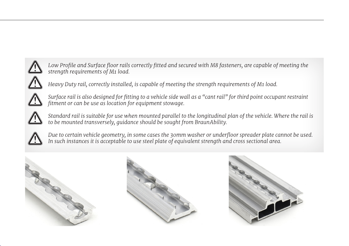
Fitting Low Prole and Surface Rails - Important notice
Fit and use
1. The minimum acceptable length of rail that can safely be installed in a vehicle to accommodate a
wheelchair is 1300 mm. This will allow one wheelchair positioned centrally. The rail must be tted
ensuring fasteners are tted to the extreme end hole positions.
2. For details of the space required within a vehicle for a wheelchair installation, reference should be made
to the guidelines within the British or International standard ISO 10542-1 part 2, ”Technical systems and
aids for disabled or handicapped persons - Wheelchair Tiedown and Occupant Restraint Systems”.
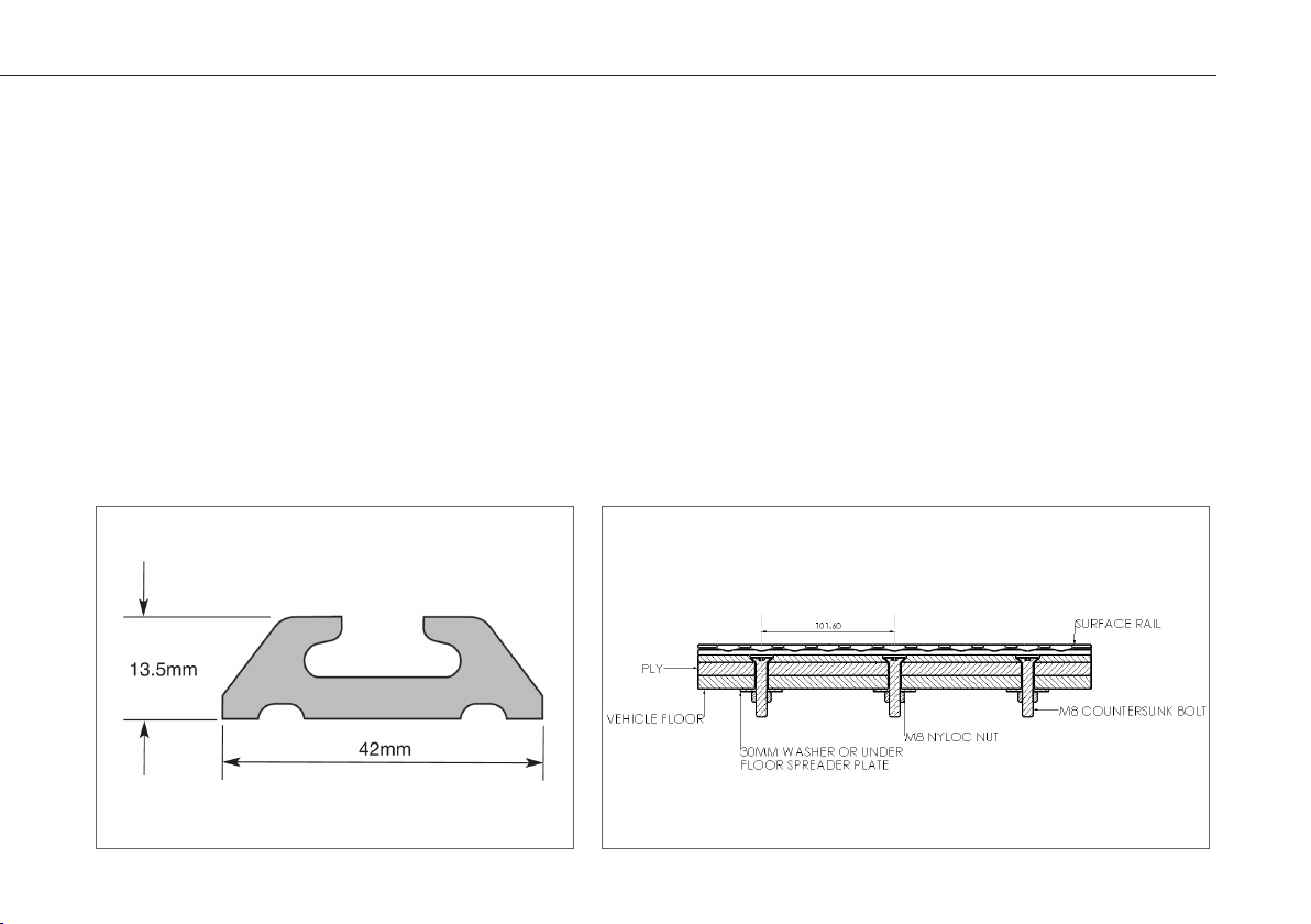
Some vehicle layouts may have problems using Low Prole and Surface rail with pre-drilled countersunk
holes due to under oor obstructions, such as box sections or angle brackets. In these situations where
a hole is “missed”, it is required to generate two new holes, one on either side of the original, with the
maximum distance between them being 101 mm.
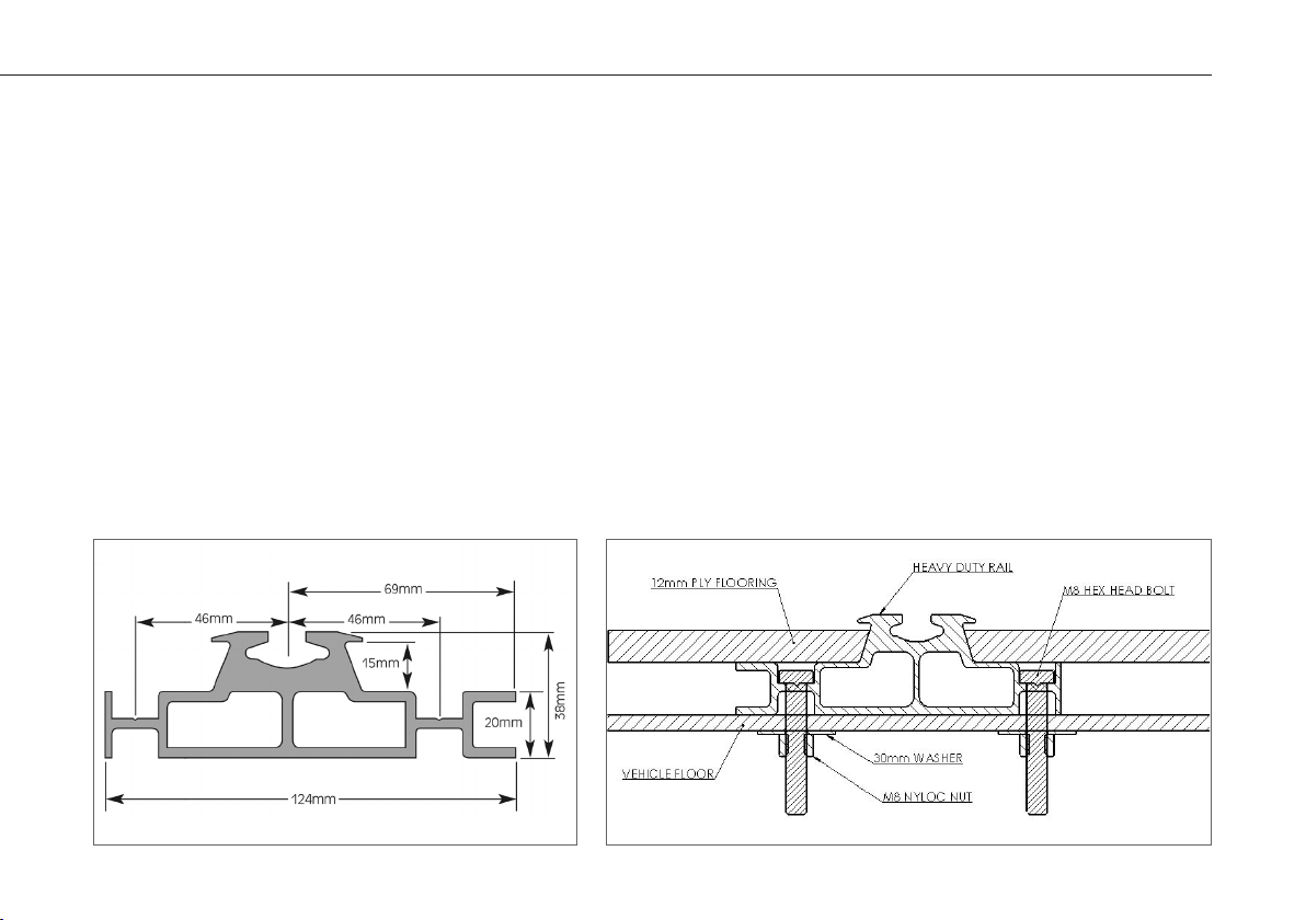
3. If the distance of the box section is greater than 101mm, we recommend drilling through the box section
and adding a crush spacer to accommodate the new hole.
4. The original unused hole must nally be lled with a short self-tapping screw with a matching head.
5. It is critical that the installed rail is at along its length and correctly positioned relative to any other rail
lengths tted in the vehicle oor. Elements within a pattern of rails must also be parallel to one another.
This is particularly important if tting Unwin “Fixed Base Equipment” or manufacturing removable seats,
to ensure they will t universally along the rails.
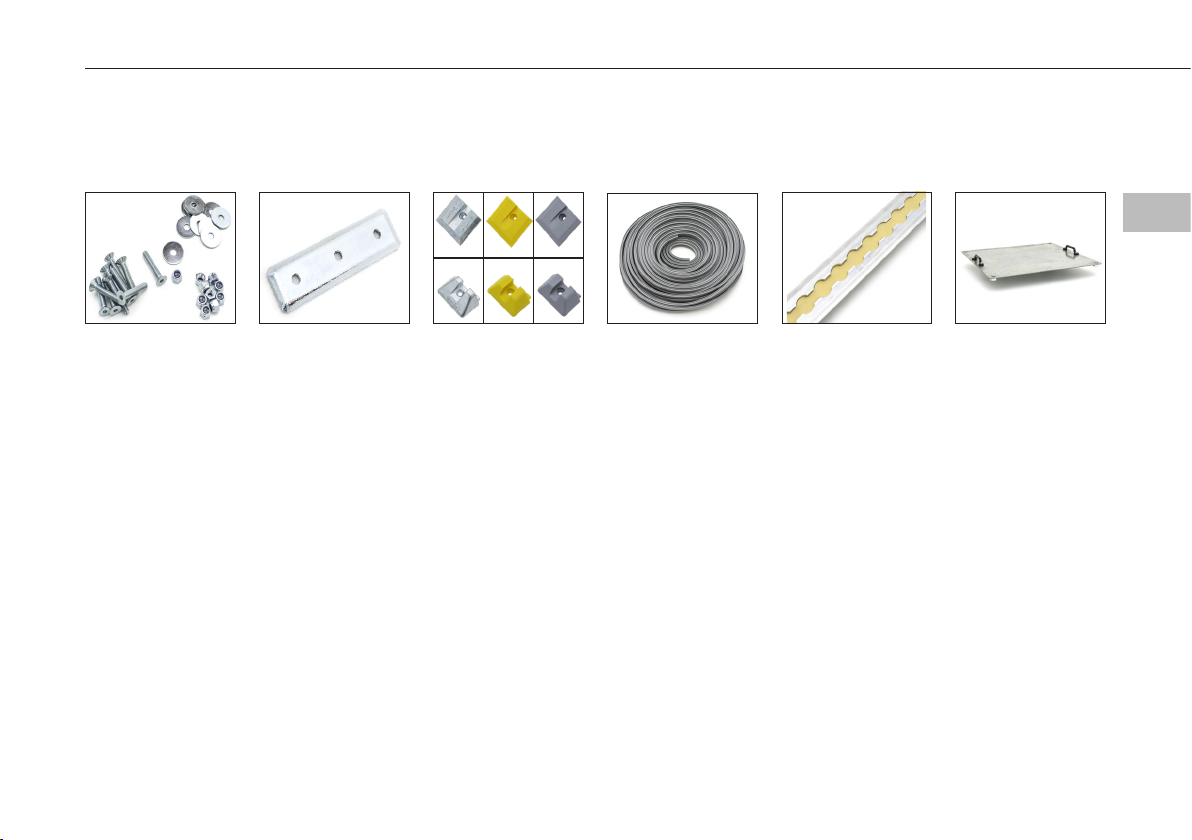
6. We recommend that installers use a rail jig to ensure that paired rails are parallel with each other within
acceptable tolerances. Our seat xtures, when correctly tted to the seat legs, will accept a rail tting
tolerance of +/- 1mm on nominal set leg centres. Rail centre to centre variations outside this tolerance
and may lead to seats jamming or to seats not being able to be tted easily in the rail at difference
positions.
7
Rails
EN
Fit and use

Fitting Heavy Duty Rail
Fit and use
1. Available in 3.95, 4.50, 4.9 and 5.5 metre lengths, this rail prole can be installed with a maximum unsupported
span of 600 mm under normal conditions.
2. Additional fasteners must be tted at the ends of the rail, in particular at the rear end.
3. Fasteners must be used on installation
4. Bolts:- M8 steel, hexagon headed grade 8.8, plated, guide length 40 - 50 mm.
5. Nuts:- M8 steel, nyloc, grade 8, plated.
6. Washers:- M8 steel, plain, plated.
7. Torque settings:- 20 nm (15 lbs/ft).
8. Under Floor Reinforcement
9. Contact BraunAbility for specic recommendations.
8Rails

Accessories
Fit and use
M8 Fasteners
(RF10 sets of 10,
RF100 set of 100)
The standard xing
kit for each rail hole
consists of:
- An M8 plated
screw grade 10.9,
- An M8 nylok nut, -
An M8 30 mm
diameter plated
steel washer.
All fasteners must
be torque-loaded to
11 Nm/(8 ft/lb)
M8 Underoor
Spreader Plate
(USP)
Under-oor spreader
plates are used with
rail fasteners in
place of washers
to enable rail to be
tted to angled oor
sections or where it
would be difcult to
position a washer.
End Caps
(LPEC, RECLY,RECLG,
SEC, RECSY, RECSG)
Line up the end cap
squarely to the end
of the installed rail,
ensuring that the
slugs locate
correctly under the
rail end.
Using the end cap as
a guide, drill through
and secure using a
no.6 counter sunk
wood screw.
Rail Trim
(RT04, RT25)
Designed to keep
the rail track clean
from dirt. Slides
into the rail central
channel and can be
cut to size.
Rail Insert
(INS)
Protext the rail from
debris. Come in
305mm length and
is pushed through
the rail central
channel.
Rail Jib
(RJ)
Ensure perfect align-
ment of rail (330mm
centre to centre)
during
installation, to avoid
tment issue .
9
Rails
EN
Fit and use

Equipment storage and maintenance
After care
• Rail inserts or strips can be tted to unused rail sections to aid housekeeping.
• Check rail for damage and corrosion.
• Rails should never come into to contact with strong acid/ alkaline solutions as this will degrade the
appearance and strength of the rail.
• If you intend to use a proprietary cleaner on or near the rails, advice should be sought from its
manufacturer to ensure it does not degrade the appearance and strength of the rail sections.
Warranty
BraunAbility products are extensively tested using BraunAbility anchorage systems, and our full warranty
normally only applies to BraunAbility equipment when used with BraunAbility branded anchorages or as
instructed.
BraunAbility have also participated in test programs with other manufacturers anchorage products and will
support warranty on the BraunAbility products when used in conjunction with such jointly tested systems.
For further details on specic applications please contact the Sales Ofce. In other situations, using
BraunAbility products, for which BraunAbility has not participated in a joint test program, a limited
BraunAbility warranty will apply.
10 Rails

Declaration of conformity
Conforms to following directives
standards and regulations /
2001/85/EC Annexe VII Paragraphs 3.8.2.8 & 3.8.2.9
76/115/EEC
R.14.07
R.107.06
BS EN 1789:2007+A2:2014
BraunAbility, Martock, 23rd April 2019
Rob Butcher
Director of Engineering
Manufacturer /
BraunAbility UK Ltd.
Unwin House
The Horseshoe Coat Road
Martock, Somerset, TA12 6EY
UK
Phone: +44 1935 827740
E-mail: sales.uk@braunability.eu
www.braunability.eu
Declares that the products /
LPRD36, LPRF36, LPRB36, LPRA36
LPRD45, LPRF45, LPRB45, LPRA45
LPRD50, LPRF50, LPRB50, LPRA50
SRD36 SRF36 SRB36 SRA36
SRD45 SRF45 SRB45 SRA45
SRD50 SRF50 SRB50 SRA50
HDRF39, HDRF47, HDRF48,
HDRF50
Accredited by URS as testing laboratory in accordance with ISO/IEC 17025:2005
Quality system certied in accordance with ISO 9001:2008
Illustrations, descriptions and specications in the user manual are based on current product
information. BraunAbility UK Ltd reserves the right to make alterations without previous notice.
© 2019 BraunAbility UK Ltd
11
Rails
EN
Fit and use

UI1264H
BraunAbility UK Ltd
Unwin House
The Horseshoe, Coat Road
Martock, Somerset, TA12 6EY
UK..
Phone: +44 1935 827 740
E-mail: info@braunability.eu
www.braunability.eu
Table of contents
Other BraunAbility Medical Equipment manuals
Popular Medical Equipment manuals by other brands

Chemyx
Chemyx FUSION X Series user manual

Myray
Myray Hyperion X5 2D Technical manual

Otto Bock
Otto Bock SiOCX TF 7T450-1 Instructions for use

Veridian Healthcare
Veridian Healthcare 11-50DP instruction manual

FIOR & GENTZ
FIOR & GENTZ NEURO MATIC Patient Information

ACCU-CHECK
ACCU-CHECK AVIVA COMBO Reference manual

Levoit
Levoit Viera user manual

Smart Caregiver
Smart Caregiver TamperProof Caregiver Key TL-2016R3 Installation and use instructions

Inspiration
Inspiration S101 L owner's manual

Gima
Gima 31524 Use and maintenance book

FREEWAY
FREEWAY Height Adjustable Shower Trolley with Liner... user manual

Manamed
Manamed PlasmaFlow Patient Start Guide