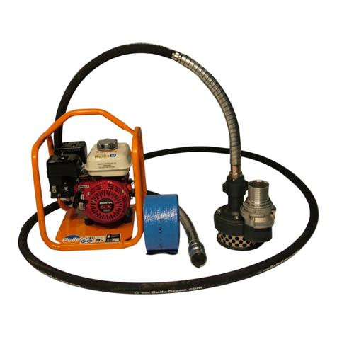
Brave MBRP750DP3 User manual

800-350-8739
1
BRP750DP3 Rev A | 3/2020
Specifications Information and Repair Parts Manual BRP750DP3
MBRP750DP3
Owner’s Manual
Brave 3” Diaphragm Water Pump
WARNING
Read and understand all instructions. Failure to follow all instructions may
result in serious injury or property damage.
• WARNING: Wear appropriate protective gear. This list includes, but is not limited to:
- safety glasses, protective boots with slip resistant soles, gloves, hearing protection.
• WARNING: Keep guards in place and in working order. Never operate the product without the guards in place.
• WARNING: LETHAL EXHAUST GAS! An internal combustion engine discharges carbon monoxide, which is a poisonous
and odorless invisible gas. Death or serious illness may result if inhaled. Operate only in an area with good ventilation.
• DANGER: Do not smoke when refueling.
• WARNING: Do not use pump in explosive atmosphere.
• WARNING: Do not pump volatile or flammable liquids such as gasoline, fuel oil, kerosene, etc.
• CAUTION: Do not attempt to operate pump, if any parts are missing or damaged.
• CAUTION: For proper handling techniques and cautions when pumping certain chemicals, contact your chemical supplier
or local agencies (fire dept etc)
• CAUTION: The engine is hot enough to cause injury, do not touch the exterior of the engine, especially the muffler and
surrounding area.
• WARNING: Even though this unit will operate with minimal supervision, it should not be left operating by itself. Depending
on the application and area unit is operating (high traffic, people in area, etc.) will dictate the necessity of having someone
watching over the unit.
• CAUTION: Do not allow pump to be located in freezing or colder weather. Damage to pump will result.
• CAUTION: Maximum discharge head is 25 feet or 10.9 PSI. Operation over this head or pressure will cause pump to stall
and/or gearbox damage.
• CAUTION: Do not control discharge capacity with a valve or similar device.
• CAUTION: If pump has stopped or stalled for any unknown reason, clean out pump cavity thoroughly. Failure to comply
with the “caution” could result in damage to crank, plunger arm or other parts of assembly.
STOP!
ADD OIL TO ENGINE BEFORE USING: Engine is shipped without oil. DO NOT start engine without first adding oil.
INSPECT COMPONENTS: Closely inspect to make sure no components are missing or damaged.
Any Questions, Comments, Problems or Parts Orders
Call Brave Support 1-800-350-8739
ITEM NUMBERS: BRP750DP3
MANUAL SERIAL TAG HERE

800-350-8739
2
BRP750DP3 Rev A | 3/2020
Specifications Information and Repair Parts Manual BRP750DP3
Please read and save this Owner’s Manual. Read this manual carefully before attempting to operate or maintain this pump. Protect yourself and others
by observing all safety information. Failure to comply with the safety instructions accompanying this product could result in personal injury and/or
property damage! Retain instructions for future reference. Brave reserves the right to discontinue any model or change specifications at any time
without incurring any obligation.
Periodic maintenance and inspection is required on all pumps to ensure proper operation. Unit must be clear of debris and sediment. Inspect for leaks
and loose bolts. Failure to do so voids warranty.
Diaphragm Pumps
DESCRIPTION
This diaphragm pump is a high capacity, self-priming (to 25 ft. lift), portable unit shipped completely assembled (except for handle). The pumps are used
for operation with fluids mixed with abrasive solids such as sand, silt, mud, sludge and waste. Not for use with pumping cement or mortar. Handles
liquids from 40º to 180º F (4º to 82 º C). Pump is capable of handling solids up to 1-5/8" diameter. For use with water and other non-flammable fluids
compatible with pump component materials.
Model
Engine Type
Material
Diaphragm
Check Valve
Gear Box
Bearings
NPT
BRP750DP3
Honda GX120
Aluminum
Thermoplastic/TPE
Neoprene
Oil Bath
Needle
3"
UNPACKING
After unpacking the unit, inspect carefully for any damage that may
have occurred during transit. Check for loose, missing or damaged
parts.
Specific Safety Information for Ga
soline Engine
Driven Pumps
1. Carefully read the instruction manuals supplied by the
engine manufacturer befor
e attempting to assemble,
disassemble or operate the engine or any other part. The
"Warning" and "Caution" statements in this manual signal
potentially hazardous conditions to the
operator or
equipment. Know when these conditions can exist. Take
necessary steps to protect personnel, as well as equipment.
Gasoline is a highly combustible fuel. Use it with care! The
improper use, handling and/or storage of gasoline can be
dangerous. Help prevent accidents by following these safety
rules:
a. Use gasoline only as a fuel, never as a cleaning fluid.
b. Always use an approved container to hold or store gasoline.
Never store gasoline in familiar containers such as milk
gallons or soda pop bottles.
c. Never store gasoline near a heater or an open flame.
d. When storing or using gasoline, make sure container is out
of the reach of children.
e. Never add gasoline to a running or hot engine. Spilled
gasoline on a hot engine may cause a fire or an explosion.
Fill gasoline tank outdoors and wipe up any spills.
f. Have a fire extinguisher nearby. Be sure extinguisher is in
operating condition – check the pressure gauge or indicator.
Be familiar with its proper use. Consult the local fire
department for the correct type of extinguisher for your
application. Extinguishers rated ABC by the National Fire
Protection Association are appropriate for all applications.
g. On permanent installations, be sure all fuel supplies have a
positive shutoff valve. Fuel lines must be of steel piping,
adequately secured and free from leaks. Do not use copper
piping on flexible lines as copper becomes hardened and
brittle and will break. Use black pipe on natural gas or
gaseous fuels, but not on gasoline or diesel fuels. Piping at
the engine should be a suitable flexible line that is
compatible with the fluid.
Positively no smoking!
2. Check engine oil, fuel levels and gear box oil levels before
initial startup each day. Stay away from moving parts due to
the danger of becoming caught in moving parts. Avoid loose
jackets, shirts, sleeves and ties. Make sure all nuts and bolts
are secure. Keep power shields and guards in place. If
adjustment MUST be made while the unit is running, use
extreme caution around hot manifolds, moving parts, etc.
3. Do not work with this equipment when mentally or physically
fatigued.
4. Be careful not to touch the exterior of the engine, especially
the muffler and the area around it. It is hot enough to be
painful or cause injury.
5. To prevent accidental starting, always remove the spark
plug or disconnect and ground the spark plug wire before
working on the engine or the equipment driven by the
engine.
6. DO NOT RUN THE ENGINE IN AN ENCLOSED AREA!!
Exhaust gases contain carbon monoxide, which is an
odorless and deadly gas that will cause death if breathed too
long.

800-350-8739
3
BRP750DP3 Rev A | 3/2020
Specifications Information and Repair Parts Manual BRP750DP3
Diaphragm Pumps
General Safety Information (All Units)
1. Know the pump application, limitations and potential hazards.
Do not use to pump flammable or explosive fluids such as
gasoline, fuel oil, or kerosene, etc. Do not use in flammable and/or
explosive atmospheres. Pump should only be used with liquids
compatible with pump component materials. Failure to follow this
warning can result in personal injury and/or property damage.
2. Provide adequate protection and guarding around moving
parts.
3. Release all pressure within the system before servicing any
component.
4. Drain all liquids from the system before servicing.
5. Secure the discharge line before starting the pump. An
unsecured discharge line will whip, possibly causing personal
injury and/or property damage.
6. Check hoses for weak or worn condition before each use,
making certain that all connections are secure.
7. Periodically inspect pump and system components. Perform
routine maintenance as required (see Maintenance Section).
8. Provide a means of pressure relief fo
r pumps whose
discharge line can be shut off or obstructed.
9. Personal Safety:
a. Wear safety glasses at all times when working with
pumps.
b. Wear a face shield and proper apparel when
pumping hazardous chemicals.
c. Keep work area clean, uncluttered and properly
lighted.
d. Keep visitors at a safe distance from the work area.
.
ASSEMBLY
HANDLE ON 3" PUMP (Refer to Figure A)
a. Remove two bolts from front holes in gear box,
mounting feet base (Ref. No. A6).
b. Place handle 3354-116-90 on top and reinstall bolts
and washers.
c. Reinstall two hex bolts and washer assemblies,
then tighten.
2. ROTATING SUCTION/DISCHARGE PORTS (OPTIONAL)
(Refer to Figure A,W,P)
In some applications, it may be preferable to have suction/discharge
ports rotated 90 degrees to be in line with driver. If so, proceed as
follows:
a. Remove four hex cap screws (Ref. No. A9), hex nut (Ref. No.
A13) and washers (Ref. Nos. A11 & A12) from pump
assembly to separate pump well (Ref. No. A3) from pump
base (Ref. No. A8).
b. Rotate pump well 90 degrees clockwise so that driver is
positioned over top of discharge plate (Ref. No. W7).
c. Be sure that pump well base and diaphragm (Ref. No. P17)
are aligned properly with one another. Then, reinstall four hex
cap screws, hex nuts and washer assemblies and tighten.
GEAR BOX OIL (Refer to Figure A,G)
3. Place pump on a level surface. Fill pump gear box (Ref. No.
A1) with gear box oil before the pump is operated. Gear oil
must meet requirements of API GL-5 and military
specification MIL-L-2105B. Remove gear box housing fill plug
(Ref. No. G6). Remove level plug (Ref. No. G5). Pour gear oil
into gear box slowly until oil comes out of level plug.
Warranty on this unit is void unless the gear box is lubricated with
appropriate gear oil listed above. DO NOT OVER FILL!
INSTALLATION
NOTE: In any installation where property damage can occur by pumps
not operating due to power outages, discharge line freezing or any
other reason, a backup system(s) and/or warning system(s) should be
used.
1. Place the pump on a level, solid foundation, locating it as
close to the liquid as possible, making the suction line as
short and direct as possible.
2. Install pipe nipples (Ref. No. A36) so the smoother side of
pipe end faces the suction and discharge hose.
Maximum discharge head is 25 feet or 10.9 psi. Operation over
this head or pressure will cause pump to stall and/or gearbox
damage. Use only rigid hoses.
3. Attach suction piping to the suction inlet (Ref. No. W2) and
discharge piping to the discharge outlet (Ref. No. W7). The
suction line should be positioned such that there is a
continual upward slope from the fluid source to the pump.
Avoid using loops or sections of pipe or fittings, which might
permit air to become trapped.
NOTE: If hose is used, be sure to use reinforced hose on both the
suction and discharge. DO NOT USE canvas or similar collapsible
materials. NEVER USE PIPE REDUCER; PIPE SIZE MUST BE
EQUAL TO OR LARGER THAN PUMP PORT SIZE. Suction line
must be airtight so that air cannot leak in and destroy priming vacuum.
On a permanent installation where piping is used, always connect a
piece of flexible hose between pump and piping so pump is free to
move slightly.
4. It is advisable to use a strainer (Ref. No. W16) on the inlet
end of the suction hose or pipe. A properly sized strainer is
supplied with this unit and should be used at all times to
prevent damage. Keep the strainer clean. If possible,
suspend it to keep it from becoming clogged with muck,
roots, debris or leaves. It is best to keep hose free of kinks
as they will restrict flow and add excess loading to pump
and gearing.
5. GASOLINE ENGINE UNITS: Follow all instructions in the
engine manual before starting the engine. Fill engine with
oil, gasoline, etc.
6. Input RPM (to pump) – Input RPM must be between 1750
and 2750 RPM. Final pump speed will be 40 strokes/min.
with a 1750 RPM input and 60 strokes/min. with a 2750
RPM input.
Do not exceed 60 strokes per minute with the diaphragm pump.
OPERATION
Operate the diaphragm pump in an upright position only.
1. This diaphragm pump is capable of priming "dry" up to
fifteen feet; it will prime much faster when it is filled with
clean water through priming cap (Ref. No. W6). Primed, it
can lift to 25 feet.
Do not control discharge capacity with a valve or similar device.
CLEARING JAM-UP
If large solids or an accumulation of sand or other sediment becomes
lodged in the pump well (Ref. No. A3) preventing the plunger arm
(Ref. No. A2) from making a full stroke, the pump should be
thoroughly cleaned as described in "If Pump Stalls" shown below.
Refer to parts list and illustration for parts identification.

800-350-8739
4
BRP750DP3 Rev A | 3/2020
Specifications Information and Repair Parts Manual BRP750DP3
Diaphragm Pumps
If pump has stopped or stalled for any unknown reason, clean
out pump cavity thoroughly. Failure to comply with the "caution"
could result in damage to crank (Ref. No. P5/P9), plunger arm
(Ref. No. P1) or other parts of assembly.
1. IF PUMP STALLS:
a. Remove handle (Ref. No. A35).
b. Remove four bolts (Ref. No. A9 & A10).
c. Clean obstruction and all debris from pump well
(Ref. No. A3).
d. Reassemble pump in reverse orde
r of
disassembly and return to service.
2. IF PLUNGER ARM (Ref. No. P1) SEIZES AND GEAR BOX
OUTPUT SHAFT (Ref. No. G8) TURNS IN CRANK (Ref.
No. P5):
a. Remove sheet metal guard (Ref. No. A4) by
loosening hand knob screws (Ref. No. A5).
b. Disassemble pump and clean as described in
steps (a) through (d) listed for stalled engine jam
up.
c. Torque the crank lock screw (Ref. No. P6) to 70
foot pounds with an appropriate torque wrench
(see Figure 3).
Figure 3
d. Reassemble the
pump in reverse order of
disassembly and return to service.
Pump jamming with an over-torqued lock screw may cause
internal damage. Under torqueing may allow the output shaft to
spin and wear parts necessitating replacement.
MAINTENANCE
1. Check gear box oil level every 20 hours of operation or at
least once a week; more often if any leakage is detected
around the gear box. Change gearbox oil after the first 40
hours of operation. Fill to the oil level plug. Change gearbox
oil every 350 hours of operation.
2. The plunger bearing (Ref. No. P3) must be greased (any
automotive grease) after every 8 hours of use. This is done
by rotating plunger bearing to the 12 o’clock position. At this
point, grease fitting will be visible through hole in guard (Ref.
No. A4). Bearing may be cleaned and kept well lubricated
by pumping grease slowly into fitting until new grease oozes
out between bearing and journal.
3. During freezing weather, be sure to drain the pump when it
is not running. Remove discharge hose and tip unit towards
discharge side.
4. Keep pump clean. After use with liquids containing foreign
materials, flush with clean water.
REPLACEMENT OF FLAPPER VALVE
(Ref. No. W15)
1. Remove two bolts (Ref. No. W3) and remove suction
priming chamber (Ref. No. W2). Replace flapper (Ref. No.
W15) on flapper pin to locate on priming chamber.
2. Remove two bolts (Ref. No. W8) and remove discharge
plate (Ref. No. W7). Replace flapper valve on flapper pin to
locate valve on pump well (Ref. No. W1).
REPLACEMENT OF DIAPHRAGM
(Ref. No. P13)
1. Remove sheet metal guard (Ref. No. A4) by loosening hand
knob screws (Ref. No. A5).
2. Rotate pump until plunger arm (Ref. No. A2) is in the down
position.
3. Remove handle (Ref. No. A35).
4. Remove pump well (Ref. No. A3) by removing screws, (Ref.
No. A9/A10).
5. Remove diaphragm by removing three nuts (Ref. No. P12)
from bolts (Ref. No. P11).
6. Replace diaphragm and reverse steps 1 through 5 for
reassembly.
GEAR BOX OVERHAULING
A completely assembled gear box is available as a replacement part
(Ref. No. G28).
DISASSEMBLY
1. Remove diaphragm (Ref. No. P13) as described in
"Replacement of Diaphragm".
2. Remove crank (Ref. No. P5) by removing machine screw
(Ref. No. P6). Use screwdriver in slot of crank to release
clamp on output shaft (Ref. No. G8).
3. Drain oil from gear box by removing drain plug (Ref. No.
G4).
4. Remove driver (Ref. Nos. A28/A32) from adapter (Ref. No.
G26) by removing four bolts (Ref. No. A27) plus 4 additional
bolts (Ref. No. A29) from engine mount bracket (Ref. No.
A16) for gas driver models. Slide driver back from adapter
until driver shaft disengages pinion (Ref. No. G20).
5. Remove adapter by removing four bolts (Ref. No. G27).
6. Remove gear box from pump base (Ref. No. A8) by
removing four bolts (Ref. No. A9 & A10).
7. Remove pinion/bearing assembly (Ref. Nos. G15, G24,
G20, G16) by pulling straight out. Use a slide hammer puller
gripping in pinion groove
8. Remove twelve bolts (Ref. No. G3) holding gear box halves
(Ref. Nos. G1 & G2) together.
9. Carefully separate gearbox halves.
10. Remove gasket (Ref. No. G22).
11. Remove output shaft/bearing assembly (Ref. Nos. G8, G9,
G12, G11, G12, G13) and idler pinion/bearing assembly
(Ref. Nos. G13, G14, G17, G18, G19).
12. Remove output shaft oil seal (Ref. No. G23)
13. Remove bearings (Ref. Nos. G15 & G16) from ends of input
pinion shaft (Ref. No. G20).
14. Remove bearings (Ref. Nos. G13 & G14) from ends of idler
pinion shaft (Ref. No. G17).
15. Remove internal spur gear (Ref. No. G19) and key (Ref. No.
G18) from idler pinion shaft.
16. Remove retaining ring (Ref. No. G10) and bearings (Ref.
Nos. G12 & G13) from ends of output shaft (Ref. No. G8).
17. Remove output gear (Ref. No. G11) and key (Ref. No. G9)
from output shaft.
REASSEMBLY
1. Assemble input pinion/bearing assembly
, idler
pinion/bearing assembly and output shaft/bearing assembly.
2. Install output shaft oil seal into gearbox output half.
Lubricate lip seal.
3. Slide output shaft through lip seal. Start output bearing in
bore in gear box output half. Position idler pinion bearing
assembly in its bore in output half. Simultaneously press
both assemblies into output half.

800-350-8739
5
BRP750DP3 Rev A | 3/2020
Specifications Information and Repair Parts Manual BRP750DP3
Diaphragm Pumps
4. Install gasket on output half.
5. Position gear box input half; align shaft bearings with bearing
bores. Press gear box halves together, align pins in output
half with pin bore in input half.
6. Secure halves together with twelve bolts.
7. Slide input pinion/bearing assembly into bore in gear box
input half. Rotate pinion during installation to make sure gear
teeth align with internal spur gear teeth.
8. Install O-ring (Ref. No. G25) on outside of pinion bearing.
9. Reassemble gear box to pump base with four bolts.
10. Reassemble adapter to gear box with four bolts.
11. Align driver shaft key (Ref. No. A26) with keyway in pinion.
Slide driver into pinion, secure to adapter with four bolts (Ref.
No. A27).
a. (Gas engine only) Attach engine to engine mount
with four additional screw assemblies (Ref. No.
A29).
12. Reassemble crank to output shaft as described under
"Operation" section.
13. Replace diaphragm as described under "Replacement of
Diaphragm" section.
14. Fill gear box with oil as described under "Assembly" section.
15. Pump should be checked daily, weekly, monthly for proper
operation.
NOTE: Only qualified service personnel should attempt to repair this
unit. Improper repair and/or assembly can cause pump damage, driver
damage and/or an electrical shock hazard depending on model.

800-350-8739
6
BRP750DP3 Rev A | 3/2020
Specifications Information and Repair Parts Manual BRP750DP3
Diaphragm Pumps
Symptom Possible Cause(s) Corrective Action
Pump will not prime or retain
1. Air leak in suction line
1. Repair or replace
prime after operating
2. Defective flapper valves
2. Replace
3. Clogged foot valve or strainer
3. Clean or replace
4. No liquid in suction line
4. Fill suction line & pump with liquid
5. Material jammed in pump well
5. Clean (See Maintenance)
Flow rate is slow
1. Incorrect driver speed
1. Increase speed (see Specifications)
2. Piping is fouled or damaged
2. Clean or replace
3. Clogged pump
3. Clean
4. Discharge line restricted or
undersized
4. Flush out piping or replace
5. Collapsible discharge hose
5. Replace with rigid or non-collapsible
hose
6. Too many bends
6. Straighten hose
7. Lines are too long
7. Shorten lines
Pump runs but no fluid
1. Faulty suction piping
1. Replace
2. Pump located too far from fluid
source
2. Place pump closer to source
3. Gate valve closed
3. Open gate valve
4. Clogged strainer
4. Clean or replace
5. Discharge height too great
5. Lower discharge height
Pump starts and stops pumping
1. Leak in suction line
1. Repair
2. Leak in foot valve
2. Repair or replace
3. Diaphragm has a crack or hole
3. Replace
4. Defective or clogged flapper valves
4. Clean or replace
Excessive noise while pump in
operation
1. Pump not secured to firm foundation
1. Secure properly
2. Restricted suction line
2. Clean or correct
Pump stalls repeatedly or
1. Discharge height over 25 feet of
head
1. Lower height (see Specifications)
stops for no apparent reason
2. Material jammed in pump well
2. Clean out pump well (See Operation &
Maintenance section)

800-350-8739
7
BRP750DP3 Rev A | 3/2020
Specifications Information and Repair Parts Manual BRP750DP3
For Repair Parts contact dealer where pump was purchased.
Please provide following information:
-Model Number
-Serial Number (if any)
Part description and number as shown in parts list
Assembled Pump – Figure A

800-350-8739
8
BRP750DP3 Rev A | 3/2020
Specifications Information and Repair Parts Manual BRP750DP3
Repair Parts List - Assembled Pump (Reference Figure A)
3" Engine
Ref.
Driven Pump
No.
Description
Part Number
Qty.
A1
Gearbox Assembly
Ref. Page 8
1
A2
Plunger/Diaphragm Assembly
Ref. Page 10
1
A3
Well Assembly
Ref. Page 11
1
A4
Plunger Guard
3354-103-00
1
A5
¼-20X1/2 Plastic Knob
1716-010-00
2
A6
½-13x1-1/2 Hex Head Cap Screw
1766-013-00
2 (3" Version)
4 (2" Version)
A6
½-13x2-1/4 Hex Head Cap Screw
1766-016-00
2
A7
½ Lock Washer
1798-001-00
4
A8
Base
3354-001-01
1
A9
½-13x2-1/4 Hex Head Bolt Grade-5
1766-016-00
2
A10
½-13x2-1/4 Hex Head Bolt Grade-5
1766-016-00
2
A11
½ Flat Washer
1798-002-00
4
A12
½ Lock Washer
1798-001-00
4
A13
½-13 Hex Nut
1782-002-00
4
A15
Mount Brace
3354-107-00
2
A16
Engine Mount
3354-108-00
1
A16
Engine Mount Kit for Hatz
335Z-101-90
1
A17
Wheel Bracket
3354-109-00
2
A18
Wheel
1663-000-00
2
A19
5/8-11x4 Hex Head Bolt
1769-000-00
2
A20
5/8 Flat Washer
1799-000-00
2
A21
5/8-11 Hex Nut
1782-020-00
2
A22
5/16-18x3/4 Hex Flange Screw
1745-002-00
4
A23
¼-20x3 Hex Head Bolt
1734-013-00
2
A24
¼ Flat Washer
1789-000-00
2
A25
¼-20 Hex Nut
1776-000-00
2
A26
3/16 Square Key
1517-001-00
1
A27
5/16-24x1 Hex Flange Screw
1753-000-00
4
A27
3/8-16X1-1/4 Hex Head Cap Screw
N/A
4
A28
Engine ¾ Keyed PTO
See Chart
1
A29
5/16-18x1-1/2 Hex Head Bolt
1748-000-00
4
A29
5/16-18 x ¾ Hex Bolt (Hatz)
1745-002-00
4
A30
5/16 Flat Washer
1790-000-00
4
A31
5/16-18 Hex Nut
1785-000-00
4
A32
Motor
N/A
1
A33
Cord Assembly
N/A
1
A34
Switch Assembly (not shown)
N/A
1
A35
Handle Kit (not shown)
3354-116-90
1
A36
Nipple Pack (2 NPT nipples)
3270-170-00
1
*Transport Handle (not shown) 3354-116-90 1

800-350-8739
9
BRP750DP3 Rev A | 3/2020
Specifications Information and Repair Parts Manual BRP750DP3
For Repair Parts contact dealer where pump was purchased.
Please provide following information:
-Model Number
-Serial Number (if any)
Part description and number as shown in parts list
Gearbox – Figure G

800-350-8739
10
BRP750DP3 Rev A | 3/2020
Specifications Information and Repair Parts Manual BRP750DP3
Repair Parts List -Gearbox (Reference Figure G)
Ref.
3" Pumps
No.
Description
Part Number
Qty.
G1
Gearbox Output Half
3354-090-01
1
G2
Gearbox Input Half
3354-091-01
1
G3
¼-20x7/8” Screws and Washer Kit (12 each)
3354-420-90
1
G4
¼ NPT Plug (drain) (kit includes 1)
1767-002-00
1
G5
¼ NPT Plug (oil level) (kit includes 1)
1767-002-00
1
G6
½ NPT Vented Plug (fill) (kit includes 1)
1767-001-00
1
G7
Lift Bracket
3354-106-00
1
G8
Output Shaft
3354-140-00
1
G9
Woodruff Key #1008
2141-000-00
1
G10
External Retaining Ring SH-112
1806-064-00
1
G11
Output Gear
3354-120-00
1
G12
Bearing –Open- 35x80x21 #6307 JEM
3354-190-00
1
G13
Bearing –Open- 20x52x15 #6304 JEM
3354-191-00
2
G14
Bearing –Open- 15x42x13 #6302 JEM
3354-192-00
1
G15
Bearing –Open- 35x62x14 #6007 JEM
3354-194-00
1
G16
Bearing –Sealed- 35x62x14 #6007 2RSJEM
3354-193-00
1
G17
Idler Pinion Shaft
3354-121-00
1
G18
Woodruff Key #406
2157-000-00
1
G19
Internal Spur Gear
2149-000-00
1
G20
Input Pinion (3/4 keyed engine)
3354-122-00
1
G20
Input Pinion (5/8 keyed 56C motor)
3354-123-00
1
G21
1/4x1 Dowel Pin
1717-002-00
1
G22
Gasket
3354-300-00
1
G23
Oil Lip Seal 1.25x1.75x0.25
2148-000-00
1
G24
Oil Lip Seal 40x62x8
2148-001-00
1
G25
O-Ring- Buna #143
2181-005-00
1
G26
Adapter (engine)
3354-093-01
1
G26
Adapter (56C motor)
3354-092-01
1
G27
5/16-18x3/4 Hex Flange Screw
1745-002-00
4
G28
Assembled Gearbox for Gas Engine Models
3354-402-90
1
(includes Ref. Nos. G1 thru G24)
G28
Assembled Gearbox for Electric Models
3354-403-90
1
(includes Ref. Nos. G1 thru G24)

800-350-8739
11
BRP750DP3 Rev A | 3/2020
Specifications Information and Repair Parts Manual BRP750DP3
For Repair Parts contact dealer where pump was purchased.
Repair Parts List - Plunger Assembly (Reference Figure P)
Ref.
3" Pumps
No.
Description
Part Number
Qty.
P1
Plunger
2134-000-01
1
P2
Retaining Ring
3350-190-00
1
P3
Plunger Bearing
2138-000-90
1
(includes Ref. No. P4)
P4
Bearing Lock Nut
Incl. w/P3
1
P5
Crank Assembly Kit
2140-000-90
1
(includes Ref. Nos. P6, P7, P8, P9)
P6
5/16-18x1/2 Socket Set Screw
Incl. w/P5
1
P7
½-13 Hex Head Cap Screw Grade-5
Incl. w/P5
1
P8
½ Lock Washer
Incl. w/P5
1
P9
Bearing Shim
Incl. w/P5
2
P10
Diaphragm Retaining Plate
2133-000-00
1
P11
Carriage Bolt Kit
3350-011-90
1
P12
½-13 Hex Nut
1782-001-00
3
P12
3/8-16 Hex Nut
N/A
-
P13
Diaphragm (Santoprene)
2132-000-00
1
Please provide following information:
-Model Number
-Serial Number (if any)
Part description and number as shown in parts list
Plunger Assembly – Figure P

800-350-8739
12
BRP750DP3 Rev A | 3/2020
Specifications Information and Repair Parts Manual BRP750DP3
For Repair Parts contact dealer where pump was purchased.
Repair Parts List - Well Assembly (Reference Figure W)
Ref.
3" Pumps
No.
Description
Part Number
Qty.
W1
Well
2120-001-00
1
W2
Suction Plate
2123-000-01
1
W3
½-13x1-1/2 Hex Head Cap Screw Grade-5
1766-013-00
2
W3
3/8-16x1-1/2 Hex Head Cap Screw Grade-5
N/A
-
W4
½ Lock Washer
1798-001-00
2
W4
3/8 Lock Washer
N/A
-
W5
Gasket
Incl. w/W6
1
W6
Cap
2124-000-00
1
(includes Ref. Nos. W5, W6)
W7
Discharge Plate
2131-000-01
1
W8
½-13x1-1/2 Hex Head Cap Screw Grade-5
1766-013-00
2
W8
3/8-16x1-1/2 Hex Head Cap Screw Grade-5
N/A
-
W9
½ Lock Washer
1798-001-00
2
W9
3/8 Lock Washer
N/A
-
W10
Check Valve (neoprene)
Incl. w/W15
2
W11
Check Valve Weight Top
Incl. w/W15
2
W12
Check Valve Weight Bottom
Incl. w/W15
2
W13
¼-20x1/2 Hex Head Cap Screw
Incl. w/W15
4
W14
1/8 diameter x 3/8 Pin
2121-000-00
2
W15
Flapper Valve Assembly Kit
3354-071-90
2
(includes Ref. Nos. W10, W11, W12, W13)
W16
Suction Strainer (not shown)
1680-000-00
1
Suction Strainer w/ Hose Shank Kit for British Threads
C311-999-90
1
W17
NPT x BSPT Pipe Nipple Kit
C370-999-90
1
Please provide following information:
-Model Number
-Serial Number (if any)
Part description and number as shown in parts list
Well Assembly – Figure W

800-350-8739
13
BRP750DP3 Rev A | 3/2020
Specifications Information and Repair Parts Manual BRP750DP3

800-350-8739
14
BRP750DP3 Rev A | 3/2020
Specifications Information and Repair Parts Manual BRP750DP3
PAGE INTENTIONALLY LEFT BLANK

800-350-8739
15
BRP750DP3 Rev A | 3/2020
Specifications Information and Repair Parts Manual BRP750DP3
This manual suits for next models
1
Table of contents
Other Brave Water Pump manuals
Popular Water Pump manuals by other brands

dooch
dooch XQ-Drive Series Installation instructions manual
Smiths Medical
Smiths Medical CADD Administration Sets with Flow Stop Quick reference card
Garden
Garden GP00 Installation and user manual
Graco
Graco 06529 instructions

SKF
SKF LINCOLN 1886 Series Original instructions
Hilti
Hilti DD VP-U Safety sheet
EINHELL Bavaria
EINHELL Bavaria BPW 48 operating instructions
Xylem
Xylem LOWARA LR Series Installation, operation and maintenance instructions

Homa
Homa CH150WA Original instruction manual

Huge Pump
Huge Pump HP 05 user manual

BRINKMANN PUMPS
BRINKMANN PUMPS TH11 Series operating instructions
Jesco
Jesco MAGDOS 20-100 Operation & maintenance instructions


