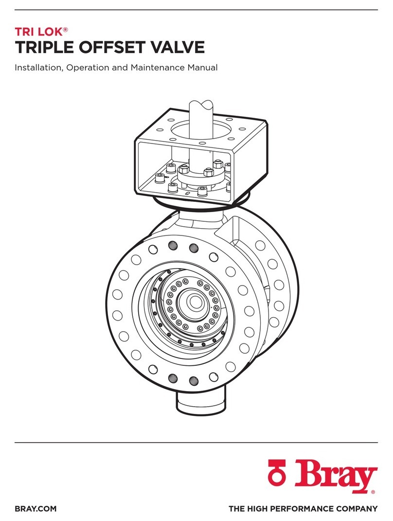
Tri Lok®
Installation, Operation and Maintenance Manual
13 |BRAY.COM
9.4.1 Seal ring replacement with the seat in
the valve (Class 150)
1. Remove valve from the pipeline. Remove the actuator
from the valve.
2. Clean the surface of the valve with compressed air,
blow out all debris around the seal ring retainer (C4)
and clean out the hex sockets of the seal ring retainer
cap screws (C5).
3. Loosen all seal ring retainer cap screws (C5), but leave
them in the valve with the seal ring retainer (C4)
attached to the disc (C1).
4. Using a wrench, rotate the valve stem (D1)
counterclockwise past the fully open position far
enough so the disc is in a position to allow seal ring
retainer and seal ring removal (C2). Be careful not to
over-rotate the stem (D1) to the point where the seal
ring (C2) or disc edge (C1) contact the body (A1). Make
sure the packing gland retainer nuts (H7) are tight
enough to prevent the valve stem (D1) from rotating on
its own under the eccentric weight of the disc (C1).
5. Remove the seal ring retaining cap screws (C5) and lock
washers (C6), and extract disc seal ring retainer (C4)
and the seal ring (C2).
6. Rotate the disc (C1) as necessary to access the seal
face on the disc (C1). Using soft tools and suitable wire
brush, carefully clean any remnants of old gasket and
foreign matter from the face of the disc (C1). Blow
out all threaded holes and the gasket groove with
compressed air.
7. Rotate the disc (C1) to its previous position to facilitate
installation of the seal ring (C2). Place a new seal ring
gasket (C3) into the groove on the disc face (C1). The
mating side of the seal ring gasket can be lightly greased
to improve retention in the groove. Place the seal ring
(C2) onto the disc (C1) making sure the alignment line
on the disc seal ring matches the locating dimple on
the disc face. Place the seal ring retainer (C4) over the
seal ring. Apply anti-seize compound to the seal ring
retainer cap screws (C5). Install all seal ring retainer cap
screws (C5) with lock washers (C6). The cap screws (C5)
should be fully threaded into the disc (C1), but remain
only finger-tight at this time.
8. Lubricate (refer to lubrication table) the sealing
surfaces of the seal ring (C2) and the seat (B1). Using
a suitable actuator, close and open the valve 2-3 times,
only closing the valve to the point where the seal ring
engages the seat. Check each time that the seal ring
makes full contact without torquing into the seat.
Attention should be paid in the closing stroke that the
seat does not scratch the seal ring. This will allow the
seal ring and seat to be properly aligned.
9. Orient the valve with the seat side facing up. Verify that
all four alignment marks (body, seat, seal ring and seal
ring retainer) are aligned.
10. Tighten the seal ring retainer cap screws (C5) using a
cross bolting technique to the torque specified in Table
3 (Pg. 15).
11. Re-apply lubricant to the sealing surfaces of the valve.
Reinstall operator or actuator and test the valve.
9.4.2 Seal ring replacement with the seat in
the valve (Class 600)
1. Remove valve from the pipeline. Remove the actuator
from the valve.
2. Clean the surface of the valve with compressed air,
blow out all debris around the seal ring retainer (C4)
and clean out the hex sockets of the seal ring retainer
cap screws (C5).
3. Loosen all seal ring retainer cap screws (C5), but leave
them in the valve with the seal ring retainer (C4)
attached to the disc (C1).
4. Using the appropriate size hex key, completely remove
the upper set screw fasteners (B6) from the seat retainer
ring (B3).
5. Below these dowels are seat retainer lower set screws
(B5) that compress the seat (B1) against the valve body.
Unscrew them until the Seat retainer ring (B4) above the
retaining ring is free to move. Remove the seat retainer
ring (B4) from the body. Carefully clean the seat retainer
ring (B3) and upper set screw fasteners (B6).
6. Extract the seat ring retainer (B3), remove the seat
alignment button (B7) that retains the seat within the
body and then remove the seat (B1).
7. Slightly grease the gasket groove in the replacement
seat, install the new seat gasket (B2), place this seat/
gasket sub-assembly into the valve body paying
attention that the groove of the seat is aligned with the
body groove and insert the seat alignment button (B7).
8. Replace set screw if necessary.
9. Adjust the seat retainer ring lower set screws (B5) until
they are flush with the bottom of the seat retainer
ring (B3). Install the seat retainer ring (B3) and the seat
retainer ring (B4) in its groove in the body.
10. Using a cross bolting technique, tighten the seat retainer
lower set screws (B5) to 50% of torque specified in
Table 4 (Pg. 16). Once all set screws are tightened to the
same torque, proceed to fully tighten them to 100% of
the listed torque value.


