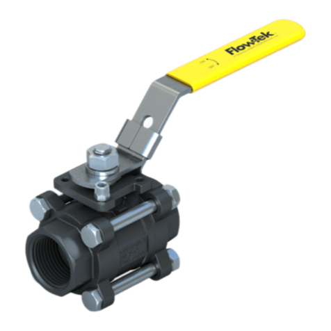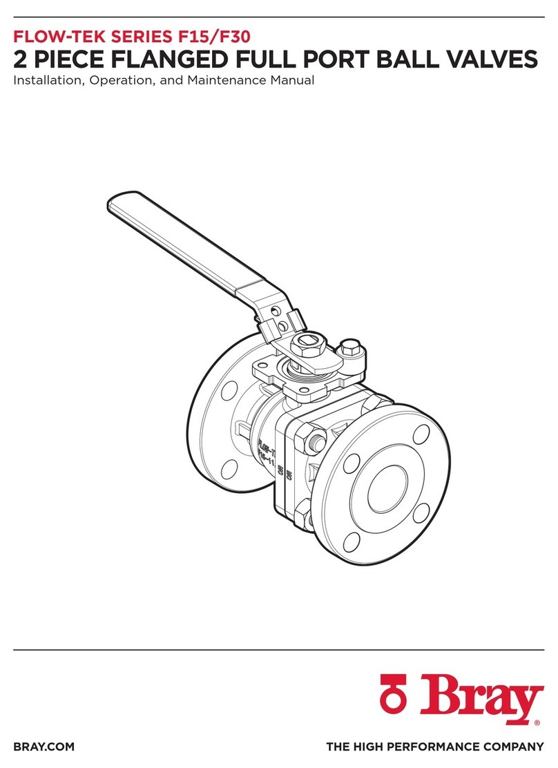
FLOW-TEK SERIES F15/F30
2 PIECE FLANGED FULL PORT BALL VALVES
Installation, Operation, and Maintenance Manual
10 of 15© 2022 BRAY INTERNATIONAL, INC. ALL RIGHTS RESERVED. BRAY.COM The Information
contained herein shall not be copied, transferred, conveyed, or displayed in any manner that would
violate its proprietary nature without the express written permission of Bray International, Inc.
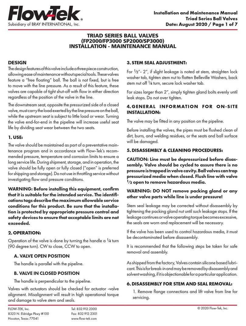
STEM SEAL ADJUSTMENT
For 1/2"- 2", if slight leakage is noted at stem, straighten lock
washer tab, tighten stem nut to flatten Belleville Washers, back
stem nut o 1/4 turn, secure lock washer tab.
For sizes larger than 2", simply tighten gland bolts evenly until
leak stops. Do not over tighten. See Table 1 for recommended
gland nut torque.
WARNING
DO NOT remove packing gland or any other valve parts while line
is under pressure!
Stem seal leakage may be corrected without disassembly by
tightening the packing gland nut until such leakage stops. If the
leakage continues or valve operating torque becomes excessive,
the seals are worn and replacement will be necessary.
Table - Recommended Gland Nut Torque
Valve Size
NPS Recommended Torque
lbs-in Valve Size
DN Recommended Torque
N-m
1/2 53 15 6
3/4 53 20 6
1 53 25 6
1-1/2 132 40 15
2 132 50 15
2-1/2 89 65 10
3 89 80 10
4 89 100 10
6 106 150 12
8 106 200 12
10 124 250 14
12 124 300 14
BALL SUPPORT PACKING ADJUSTMENT
Ball Support packing adjustment may be required in the
rare event that the pin packing develops a leak. The below
instructions should be followed in the event of a leak to adjust the
packing. Note that the position of the ball support comes pre-set
from the factory. Adjustment of the pin seat position may only be
required if the ball support components have been replaced.
1. Loosen the set nut (35) on the tuning screw (36) by turning
the nut counter-clockwise while holding the screw stationary
with an open end wrench.
2. With the set nut (35) loose, turn the support nut (34)
clockwise to compress pin packing (32) as necessary to stop
leakage of line media around support nut threads.
3. Using finger pressure only, rotate the tuning screw (36) in the
clockwise direction until resistance is felt from the support
pin seat (31) contacting the ball surface. Then, rotate the
tuning screw (36) ¼ turn in the counter-clockwise direction.
4. Lock the tuning screw (36) in position with the set nut (35)by
holding the tuning screw (36) head stationary with an open
end wrench while firmly tightening the set nut (35) in the
clockwise direction.
Ball
Ball Support
Clockwise
Counter
Clockwise
31 Pin Seat
32 Pin Packing
33 Support Pin
34 Support Nut
35 Set Nut
36 Turning Screw
Clockwise
Counter
Clockwise
31 Pin Seat
32 Pin Packing
33 Support Pin
34 Support Nut
35 Set Nut
36 Turning Screw


