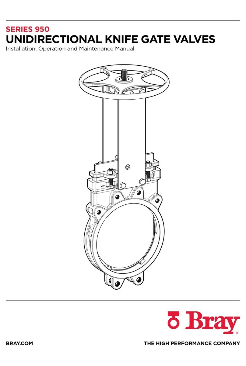
SERIES 740 BIDIRECTIONAL KNIFE GATE VALVE
Installation, Operation and Maintenance Manual
© 2019 BRAY INTERNATIONAL. ALL RIGHTS RESERVED. BRAY.COM The Information contained
herein shall not be copied, transferred, conveyed, or displayed in any manner that would violate its
proprietary nature without the express written permission of Bray International, Inc.
17 of 20
Figure 24: Remove the gate.
14.0 SEAL REPLACEMENT
14.1 Relieve the line pressure and close the valve. Flushing the line may
be necessary. Remove the valve from the line by loosening the
flange mounting bolts, studs, and nuts.
14.2 Clamp the valve in the vertical position to a fixture. Do not block
the valve port when clamping the valve. An overhead hoist may
be needed for larger size valves.
14.3 Disconnect the stem from the gate by removing the clevis, bolts,
and nuts. See Figure 23.
14.4 Remove the actuator and superstructure from the valve.
14.5 Remove the gland nuts, gland, and gland packing from the valve.
14.6 Remove the gate carefully from the valve body. Clean the gate and
smooth out any rough surfaces. Figure 24.
14.7 Remove the seal by pulling it out of the top of the valve body.
Figure 25.
14.8 Clean and inspect the body for any damage, particularly sharp
edges that may cut the seal. Smooth out if necessary.
14.9 Saturate the body seal groove area with a good water–soluble
lubricant that will not affect the seal or process. Inspect the new
seal and saturate both ends of the seal.
14.10 Insert one end of the seal from the top side. Reach into the
port area and pull the seal through the groove of the port area
and pull the seal from the top of the body. Ensure the seal is
not overstretched.
14.11 Install the gate and mount the actuator or handwheel. Operate
the gate to seat the seal into the bottom groove and cycle several
times. With the seal forced fully into the seal groove, cut each end
of the seal off to the required extended length.
Refer to Table 6.
14.12 While leaving the gate in the closed position, retract the actuator
to the open position.
14.13 Install the PTFE wiper and repack the valve. Adjust the packing
for tight shutoff when the valve is installed and pressurized to
operating pressure.
Figure 23: Lift clevis after removing
nuts & bolts.
Figure 25: Remove seal
CAUTION
Relieve line pressure before attempting to remove the valve from the line
to avoid personnel injury and/or equipment damage. If the valve has a
pneumatic actuator, solenoid valve, limit switches, or other accessories,
disconnect electrical and pneumatic supply.
Table 6: Seal Length
Valve Size Max Length
Up to 8" 20 mm
10" - 16" 25 mm
18" and Up 30 mm


