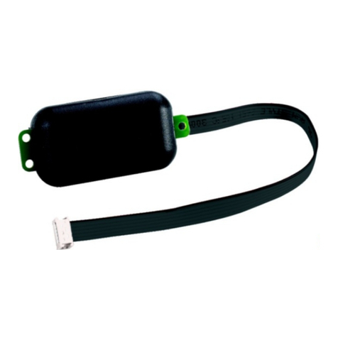
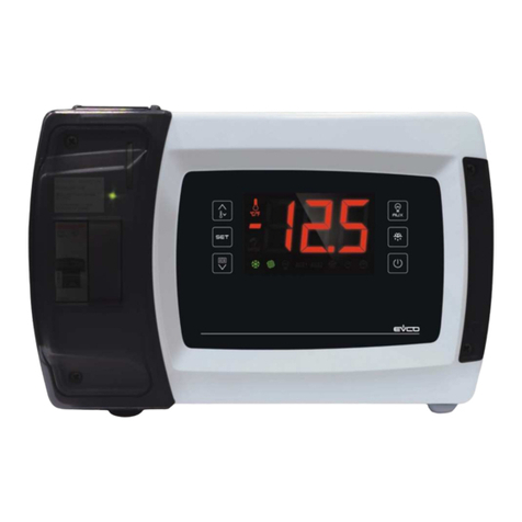
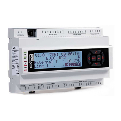
Evco EVDRIVE03 User manual

EVCO S.p.A. EVDRIVE03 | User manual ver. 3.7 | Code 144EPDE374
Pa e 1 of 76
EVDRIVE03
Electronic expansion valves drivers
ENGLISH
USER MANUAL ver. 3.
CODE 144EPDE3 1
4

EVCO S.p.A. EVDRIVE03 | User manual ver. 3.7 | Code 144EPDE374
Pa e 2 of 76
Important
Important
Read this document carefully before installin and usin the device and follow all the additional information; keep this
document close to the device for future consultations.
The followin symbols support the readin of the document:
it indicates a su estion
it indicates an additional information.
The device must be disposed accordin to the local le islation about the collection for electrical and electronic
equipment.

EVCO S.p.A. EVDRIVE03 | User manual ver. 3.7 | Code 144EPDE374
Pa e 3 of 76
Index
1
INTRODUCTION ................................................................................................................................... 5
1.1
Introduction ........................................................................................................................................ 5
1.2
Summarizin table of the main features and available models ................................................................... 6
2
DESCRIPTION ...................................................................................................................................... 8
2.1
Description .......................................................................................................................................... 8
3
SIZE AND INSTALLATION ...................................................................................................................... 9
3.1
Size .................................................................................................................................................... 9
3.2
Installation ........................................................................................................................................ 10
3.3
Additional information for the installation .............................................................................................. 10
4
ELECTRICAL CONNECTION .................................................................................................................. 11
4.1
Meanin of the connectors .................................................................................................................. 11
4.2
Example of electrical connection .......................................................................................................... 15
4.3
Additional information for electrical connection ...................................................................................... 16
5
USER INTERFACE ............................................................................................................................... 17
5.1
Preliminary information ....................................................................................................................... 17
5.2
Keyboard (not available in the blind versions) ........................................................................................ 17
5.3
Si nallin LEDs .................................................................................................................................. 17
6
OPERATION ....................................................................................................................................... 19
6.1
Switch on and resynchronization .......................................................................................................... 19
6.2
Operatin mode ................................................................................................................................. 21
6.2.1
Preliminary information ............................................................................................................... 21
6.3
Stand-by and operation mode selection ................................................................................................ 21
6.4
Enablin EVDRIVE03 .......................................................................................................................... 22
6.5
Analo positioner control ..................................................................................................................... 22
6.6
Al orithm start-up .............................................................................................................................. 23
6.7
Manual mode ..................................................................................................................................... 23
6.8
Debu in mode ................................................................................................................................ 24
6.9
Superheat control al orithm ................................................................................................................ 24
7
CONFIGURATION ............................................................................................................................... 26
7.1
Unit of measurements ........................................................................................................................ 26
7.2
Confi urin a built-in version ............................................................................................................... 26
7.3
Confi urin a blind version .................................................................................................................. 31
7.4
Confi urin the device throu h the pro rammin key EVKEY10 ............................................................... 32
7.5
Connectin the device throu h the set-up software system Parameters Mana er ....................................... 33
7.6
Main menu ........................................................................................................................................ 33
7.7
Backup and restore ............................................................................................................................ 34
7.8
List of confi uration parameters ........................................................................................................... 35
8
SERIAL COMMUNICATION ................................................................................................................... 53
8.1
Preliminary information ....................................................................................................................... 53
8.2
CANBUS serial communication ............................................................................................................. 53
8.3
MODBUS serial communication ............................................................................................................ 55
9
ALARMS AND ERRORS ........................................................................................................................ 56
9.1
Alarms and errors .............................................................................................................................. 56
9.2
Memory error .................................................................................................................................... 56
9.3
Confi uration error ............................................................................................................................. 56
9.4
Communication error .......................................................................................................................... 57
9.5
Probe error ........................................................................................................................................ 58

EVCO S.p.A. EVDRIVE03 | User manual ver. 3.7 | Code 144EPDE374
Pa e 4 of 76
9.6
Power failure and backup battery error ................................................................................................. 58
9.7
Al orithm status ................................................................................................................................ 59
9.8
Al orithm protection functions ............................................................................................................. 59
9.8.1
LoSH ......................................................................................................................................... 59
9.8.2
HiSH ......................................................................................................................................... 59
9.8.3
LOP .......................................................................................................................................... 59
9.8.4
MOP .......................................................................................................................................... 60
9.8.5
LowPressure .............................................................................................................................. 60
9.9
Parameters error ................................................................................................................................ 60
10
ACCESSORIES ................................................................................................................................... 61
10.1
Pro rammin key EVKEY10 ............................................................................................................. 61
10.1.1
Introduction ............................................................................................................................... 61
10.1.2
Description ................................................................................................................................ 61
10.1.3
Size .......................................................................................................................................... 61
10.1.4
Connection to the device ............................................................................................................. 61
10.2
Pro rammin kit EVIF20TUXI ........................................................................................................... 62
10.2.1
Introduction ............................................................................................................................... 62
10.2.2
Description ................................................................................................................................ 62
10.2.3
Size .......................................................................................................................................... 63
10.2.4
Connection to the Personal Computer ........................................................................................... 63
10.3
Non optoisolated RS-485/USB serial interface EVIF20SUXI .................................................................. 63
10.3.1
Introduction ............................................................................................................................... 63
10.3.2
Description ................................................................................................................................ 64
10.3.3
Size .......................................................................................................................................... 65
10.3.4
Connection to the Personal Computer ........................................................................................... 65
10.4
Backup module EPS4B .................................................................................................................... 66
10.4.1
Introduction ............................................................................................................................... 66
10.4.2
Description ................................................................................................................................ 66
10.4.3
Size .......................................................................................................................................... 67
10.4.4
Connection to the device ............................................................................................................. 67
11
TECHNICAL DATA ............................................................................................................................... 68
11.1
Technical data ............................................................................................................................... 68

EVCO S.p.A. EVDRIVE03 | User manual ver. 3.7 | Code 144EPDE374
Pa e 5 of 76
1INTRODUCTION
1.1 Introduction
The drivers of the EVDRIVE03 series are devices studied for the mana ement of bipolar stepper electronic expansion
valves.
They are available in built-in and blind version (accordin to the model).
The user interface of the built-in versions consists of a LCD raphic display, of six buttons and uarantees an index of
protection IP40.
The blind versions must be used with a remote user interface.
They can be powered both in alternatin and in direct current (24 VAC/24... 37 VDC).
The drivers can work with the most common temperature probes (NTC and Pt 1000) and with the most common
pressure transducers (0-20 mA, 4-20 mA, 0-5 V ratiometric and 0-10 V).
They have confi urable di ital inputs (enable the operation, chan e parameters set, backup module status, etc.) and a
5 res. A @ 250 VAC di ital output (electromechanical relay) confi urable as alarm output, solenoid valve or
resynchronization valve.
Throu h the pro rammin port it is possible to make the upload and the download of the confi uration parameters
(usin the pro rammin key EVKEY10); throu h this port (or the RS-485 one), it is also possible to connect the
devices to the set-up software system Parameters Mana er or to the plants monitorin and supervision one RICS
(throu h a serial interface).
Throu h the CAN communication port (or the RS-485 one) it is possible to connect the devices to a controller or to a
remote user interface instead.
Throu h the backup module EPS4B it is finally possible to close the valve in case of lack of power supply of the drivers.
Installation is on DIN rail.
Amon the several functions one hi hli hts the possibility to work both in stand alone mode and under the supervision
of a controller, the mana ement both of eneric electronic expansion valves and of the most common valves Sporlan
and Alco and the mana ement of the backup probes.

EVCO S.p.A. EVDRIVE03 | User manual ver. 3.7 | Code 144EPDE374
Pa e 6 of 76
1.2 Summarizing table of the main features and available
models
The followin table shows the main features of the devices and the available models.
The character “ / “ means the feature can be set throu h a confi uration parameter.
Version (according to the model)
built-in LCD •
blind • • •
User interface
71.0 x 128.0 mm (2.795 x 5.039 in;
L x H), 4 DIN modules • • • •
128 x 64 pixel sin le colour (black with
rearli htin throu h white LEDs) LCD raphic
display
•
number of buttons 6
index of protection IP20
IP40 the front
IP20
IP40 the front
IP20
IP40 the front
IP20
IP40 the front
Main connections
extractable screw terminal blocks • • • •
Power supply
24 VAC or 24... 37 VDC • • • •
Analog inputs
analo input 1 (suction temperature backup
probe / suction pressure backup probe)
NTC / Pt 1000
/ 0-20 mA /
4-20 mA /
0-5 V
NTC / Pt 1000
/ 0-20 mA /
4-20 mA /
0-5 V
NTC / Pt 1000
/ 0-20 mA /
4-20 mA /
0-5 V
NTC / Pt 1000
/ 0-20 mA /
4-20 mA /
0-5 V
analo input 2 (suction temperature backup
probe / suction pressure backup probe)
NTC / Pt 1000
/ 0-20 mA /
4-20 mA /
0-5 V
NTC / Pt 1000
/ 0-20 mA /
4-20 mA /
0-5 V
NTC / Pt 1000
/ 0-20 mA /
4-20 mA /
0-5 V
NTC / Pt 1000
/ 0-20 mA /
4-20 mA /
0-5 V
analo input 3 (suction temperature probe) NTC / Pt 1000 NTC / Pt 1000 NTC / Pt 1000 NTC / Pt 1000

EVCO S.p.A. EVDRIVE03 | User manual ver. 3.7 | Code 144EPDE374
Pa e 7 of 76
analo input 4 (suction pressure probe)
0-20 mA /
4-20 mA /
0-5 V / 0-10 V
0-20 mA /
4-20 mA /
0-5 V / 0-10 V
0-20 mA /
4-20 mA /
0-5 V / 0-10 V
0-20 mA /
4-20 mA /
0-5 V / 0-10 V
Free of voltage digital inputs
di ital input 1 (enable the operation / chan e
parameters set / resynchronization command
/ backup module status)
• • • •
di ital input 2 (enable the operation / chan e
parameters set / resynchronization command
/ backup module status)
• • • •
High voltage digital inputs
on-off switchin (enable the operation /
chan e parameters set / resynchronization
command / backup module status)
• • •
Digital outputs (electromechanical relays; res. A @ 250 VAC)
di ital output 1 (alarm output / solenoid valve
/ resynchronization valve) 5 A 5 A 5 A 5 A
Communication ports
CAN port with CANBUS communication
protocol • • •
RS-485 port with MODBUS communication
protocol • •
pro rammin port with MODBUS
communication protocol • • • •
Codes
codes EPD4BX3 EPD4BC3 EPD4BF3 EPD4DF3
For further information look at chapter 11 “TECHNICAL DATA”; for further models please contact the EVCO sales
network.

EVCO S.p.A. EVDRIVE03 | User manual ver. 3.7 | Code 144EPDE374
Pa e 8 of 76
2DESCRIPTION
2.1 Description
The followin drawin shows the aspect of EVDRIVE03.
The followin table shows the meanin of the parts of EVDRIVE03.
Part Meaning
1 di ital output
2 analo inputs and free of volta e di ital inputs
3 CAN port (not available in model EPD4BX3 and EPD4BM3)
4 CAN port line termination (not available in model EPD4BX3 and EPD4BM3)
5 display and keyboard (not available in models EPD4BX3, EPD4BC3 and EPD4BF3)
6 reserved
7 bipolar stepper motor output
8 pro rammin port
9 power supply
10 RS-485 port (not available in models EPD4BX3 and EPD4BC3)
11 RS-485 port line termination (not available in models EPD4BX3 and EPD4BC3)
12 si nallin LEDs
13 hi h volta e di ital input (not available in model EPD4BX3)
For further information look at the followin chapters.

EVCO S.p.A. EVDRIVE03 | User manual ver. 3.7 | Code 144EPDE374
Pa e 9 of 76
3SIZE AND INSTALLATION
3.1 Size
The followin drawin shows the size of EVDRIVE03 (4 DIN modules); size in mm (in).

EVCO S.p.A. EVDRIVE03 | User manual ver. 3.7 | Code 144EPDE374
Pa e 10 of 76
3.2 Installation
On DIN rail 35.0 x 7.5 mm (1.377 x 0.295 in) or 35.0 x 15.0 mm (1.377 x 0.590 in).
To install the device operate as shown in the followin drawin .
1 2
To remove the device remove possible extractable screw terminal blocks plu ed at the bottom first, then operate on
the DIN rail clips with a screwdriver as shown in the followin drawin .
3 4
To install the device a ain press the DIN rail clips to the end first.
3.3 Additional information for the installation
- make sure the workin conditions of the device (operatin temperature, operatin humidity, etc.) are in the
limits indicated; look at chapter 11 “TECHNICAL DATA”
- do not install the device close to heatin sources (heaters, hot air ducts, etc.), devices havin bi ma netos
(bi speakers, etc.), locations subject to direct sunli ht, rain, humidity, dust, mechanical vibrations or bumps
- accordin to the safety le islation, the protection a ainst possible contacts with the electrical parts must be
ensured by a correct installation of the device; all the parts which ensure the protection must be fixed so that
you can not remove them if not by usin a tool.

EVCO S.p.A. EVDRIVE03 | User manual ver. 3.7 | Code 144EPDE374
Pa e 11 of 76
4ELECTRICAL CONNECTION
4.1 Meaning of the connectors
The followin drawin shows the connectors of EVDRIVE03.
The followin tables show the meanin of the connectors; for further information look at chapter 11 “TECHNICAL
DATA”.
Digital output
Electromechanical relay.
Terminal Meaning
CO1 common di ital output
NO1 normally open contact di ital output
Analog inputs and free of voltage digital inputs
Part Meaning
+12V power supply 0-20 mA/4-20 mA/0-10 V transducers (12 VDC ±10%, 60 mA max.)
+5V power supply 0-5 V ratiometric transducers (5 VDC ±5%, 40 mA max.)
GND round analo inputs and free of volta e di ital inputs
DI1 di ital input 1 (non optoisolated free of volta e contact; 5 V when not loaded, 3.3 mA when loaded)
DI2 di ital input 2 (non optoisolated free of volta e contact; 5 V when not loaded, 3.3 mA when loaded)

EVCO S.p.A. EVDRIVE03 | User manual ver. 3.7 | Code 144EPDE374
Pa e 12 of 76
GND common analo inputs and free of volta e di ital inputs
AI1 analo input 1 (which can be set via confi uration parameter for NTC/Pt 1000 probes and for
0-20 mA/4-20 mA/0-5 V ratiometric transducers)
AI2 analo input 2 (which can be set via confi uration parameter for NTC/Pt 1000 probes and for
0-20 mA/4-20 mA/0-5 V ratiometric transducers)
GND common analo inputs and free of volta e di ital inputs
AI3 analo input 3 (which can be set via confi uration parameter for NTC/Pt 1000 probes)
AI4 analo input 4 (which can be set via confi uration parameter for 0-20 mA/4-20 mA/0-5 V
ratiometric/0-10 V transducers)
CAN port (not available in model EPD4BX3)
Non optoisolated CAN port, with CANBUS communication protocol.
Terminal Meaning
CAN+ si nal +
CAN- si nal -
GND round
- the maximum number of devices that can make a CAN network (32) depends on the bus load; the bus
load depends on the baud rate of the CANBUS communication and on the kind of device in the network
(for example: a CAN network can be made of a pro rammable controller, of four I / O expansions and of
four user interfaces with baud rate 500,000 baud)
- connect the CAN port usin a twisted pair
- do not connect more than four I / O expansions.
For the settin s about the CAN port look at chapter 7 “CONFIGURATION”.
Terminal Meaning
GND round
VDC power supply remote user interface (22... 35 VDC, 100 mA max.)

EVCO S.p.A. EVDRIVE03 | User manual ver. 3.7 | Code 144EPDE374
Pa e 13 of 76
CAN port line termination (not available in model EPD4BX3)
Position microswitch 1 on position on (120 Ω, 0.25 W) to plu in the CAN port line termination (plu in the termination
of the first and of the last element of the network).
Reserved
Reserved.
Bipolar stepper motor output
Terminal Meaning
V BATT backup power supply input
SHIELD common bipolar stepper motor shielded cable
SO 1A bipolar stepper motor coil 1
SO 1B bipolar stepper motor coil 1
SO 2A bipolar stepper motor coil 2
SO 2B bipolar stepper motor coil 2
With reference to the previous table, the followin one shows how to connect to EVDRIVE03 the most common
electronic expansion valves Sporlan and Alco.
Terminal
Wire (color)
Sporlan SER, SEI,
SEH and ESX Alco EXM/EXL-246 Alco EX4, EX5, EX6,
EX and EX8 Danfoss ETS
SO 1A reen wire blue wire blue wire reen wire
SO 1B red wire yellow wire brown wire red wire
SO 2A black wire white wire white wire white wire
SO 2B white wire oran e wire black wire black wire
Programming port
Non optoisolated pro rammin port, with MODBUS communication protocol.

EVCO S.p.A. EVDRIVE03 | User manual ver. 3.7 | Code 144EPDE374
Pa e 14 of 76
Power supply
Terminal Meaning
V≅+ power supply device (not isolated; 24 VAC +10% -15%, 50/60 Hz ±3 Hz, 40 VA max. or
24... 37 VDC, 22 W max.)
V≅- power supply device (not isolated; 24 VAC +10% -15%, 50/60 Hz ±3 Hz, 40 VA max. or
24... 37 VDC, 22 W max.)
- protect the power supply with a fuse rated 2 A-T 250 V
- if the device is powered in direct current, it is necessary to respect the polarity of the power supply
volta e.
RS-485 port (not available in models EPD4BX3 and EPD4BC3)
Non optoisolated RS-485 port, with MODBUS communication protocol.
Terminal Meaning
GND round
RS485+ D1 = A = + (terminal 1 of the transceiver)
RS485- D0 = B = - (terminal 0 of the transceiver)
- connect the RS-485 MODBUS port usin a twisted pair.
For the settin s about the RS-485 MODBUS port look at chapter 7 “CONFIGURATION”.
RS-485 port line termination (not available in models EPD4BX3 and EPD4BC3)
Position microswitch 1 on position on (120 W, 0.25 W) to plu in the RS-485 port line termination (plu in the
termination of the first and of the last element of the network).
High voltage digital input
Hi h volta e di ital input (if present).
Part Meaning
DIHV1 hi h volta e di ital input (optoisolated contact; 115 VAC -10%... 230 VAC +10%)

EVCO S.p.A. EVDRIVE03 | User manual ver. 3.7 | Code 144EPDE374
Pa e 15 of 76
4.2 Example of electrical connection
The followin drawin shows an example of electrical connection of EVDRIVE03.
Please note the power supply of EVDRIVE03 and that of EPS4B are not isolated one another: it is
important to wire correctly the devices as indicated in the drawing.

EVCO S.p.A. EVDRIVE03 | User manual ver. 3.7 | Code 144EPDE374
Pa e 16 of 76
4.3 Additional information for electrical connection
- do not operate on the terminal blocks of the device usin electrical or pneumatic screwers
- if the device has been moved from a cold location to a warm one, the humidity could condense on the inside;
wait about an hour before supplyin it
- make sure the power supply volta e, the electrical frequency and the electrical power of the device correspond
to those of the local power supply; look at chapter 11 “TECHNICAL DATA”
- disconnect the power supply of the device before servicin it
- do not use the device as safety device
- for the repairs and for information about the device please contact the EVCO sales network.

EVCO S.p.A. EVDRIVE03 | User manual ver. 3.7 | Code 144EPDE374
Pa e 17 of 76
5USER INTERFACE
5.1 Preliminary information
EVDRIVE03 is available in built-in and blind version (accordin to the model).
The built-in versions can be pro rammed throu h the user interface, the blind ones must be used with a remote user
interface (for example Vgraph): both the versions can be pro rammed throu h the set-up software system
Parameters Mana er or throu h the plants monitorin and supervision one RICS; look at chapter 7 “CONFIGURATION”.
Usin the pro rammin key EVKEY it is also possible to make the upload and the download of the confi uration
parameters.
5.2 Keyboard (not available in the blind versions)
The followin table shows the meanin of the keyboard.
Button Preset function
cancel, hereinafter also called “button ESC”
move to left, hereinafter also called “button LEFT”
increase, hereinafter also called “button UP”
decrease, hereinafter also called “button DOWN”
move to ri ht, hereinafter also called “button RIGHT”
confirmation, hereinafter also called “button ENTER”
5.3 Signalling LEDs
The followin table shows the meanin of the LEDs at the front of the device.
LED Meaning
ON
LED power supply
if it is lit, the device will be powered
if it is out, the device will not be powered
STEP 1
LED stepper output 1
if it is lit, the valve will be stopped and completely closed
if it flashes slowly, the valve will be stopped and completely open
if it flashes quickly, the valve will be movin
if it is out, the valve will be stopped and open in an intermediary position

EVCO S.p.A. EVDRIVE03 | User manual ver. 3.7 | Code 144EPDE374
Pa e 18 of 76
STEP 2
LED auxiliary
if parameter Ph80 = 0, LED status
if it is lit, the device will be workin in superheatin al orithm modality
if it flashes slowly, the device will be workin in manual or in debu er modality
if it flashes quickly, the device will be workin in analo positioner modality
if it is Off, the device will be in a different status
if parameter Ph80 = 1, LED MOP/LOP alarm
if it flashes quickly, the MOP alarm will be runnin
if it flashes slowly, the LOP alarm will be runnin
if it is out, no MOP/LOP alarm will be runnin
if parameter Ph80 = 2, LED hi h superheatin /low superheatin alarm
if it flashes quickly, the hi h superheatin alarm will be runnin
if it flashes slowly, the low superheatin alarm will be runnin
if it is out, no hi h superheatin /low superheatin alarm will be runnin
LED alarm
if it is On, an alarm will be runnin
if it flashes slowly, it is necessary to disable the device so that the modification of the confi uration
parameters has effect
if it flashes quickly, it is necessary to switch off/on the power supply of the device so that the
modification of the confi uration parameters has effect
if it is Off, no alarm will be runnin
COM
LED communication
if it is ON, a device-controller communication alarm will be runnin and the valve is halted
if it flashes slowly, the device-controller communication will be in the warnin status
if it flashes quickly, a device-controller communication alarm will be runnin and the device will be
workin in stand alone modality
if it is OFF, the device will be workin in stand alone modality or no device-controller communication
alarm will be runnin

EVCO S.p.A. EVDRIVE03 | User manual ver. 3.7 | Code 144EPDE374
Pa e 19 of 76
6OPERATION
6.1 Switch on and resynchronization
At switch-on and after a resynchronization, the fundamental parameters for movin the motor are acquired.
The parameters of pressure and temperature units of measure are loaded at switch-on, and, if necessary, is performed
the conversion of all the parameters of pressure and temperature.
The parameters that are loaded only durin the initialization phase, and therefore require a reset to be loaded, are
referred to as manufacturer parameters (Manufacturer menu) and can be modified only in the stand-by state.
To select the desired valve, it is necessary to set the correct value in Valve selection (parameter Pi07).
Settin this parameter to a value of 0 ( eneric valve) means settin the parameters Pr50 and parameter Pr55 is
required, with which it is possible to specify the value of each valve parameter.
With function “Copy selected to eneric valve” it is possible to copy the default values of the selected valve into the
ones of the eneric valve, in order to use them as reference for possible modifications.
If a predefined valve is selected (parameter Pi07 > 0), all relevant parameters specific to that valve are loaded
automatically from the flash memory, accordin to the table below:
Pi07
Valve name
Minimum re ulation
steps [step]
Maximum
re ulation
steps [step]
Overdrivin
steps [step]
Steppin
rate [step/s]
Operatin phase
current [mA]
Holdin phase
current [mA]
Recommended Step
Mode
0 Generic valve 0 0 0 0 0 0 Full step 2ph
1 Sporlan CO2 0 2500 3125 400 275 0 Full step 2ph
2 Sporlan SER AA
Sporlan SER A
Sporlan SER B
Sporlan SER C
Sporlan SER D
0 2500 3500 400 120 0 Full step 2ph
3 Sporlan SERI F
Sporlan SERI G
Sporlan SERI J
Sporlan SERI K
Sporlan SERI L
0 2500 3500 400 120 0 Full step 2ph
4 Sporlan SER 1.5 to 20 0 1596 3500 400 160 0 Full step 2ph
5 Sporlan SEI 0.5 to11 0 1596 3500 400 160 0 Full step 2ph
6 Sporlan SEI 30 0 3193 6500 400 160 0 Full step 2ph
7 Sporlan SEI 50 0 6386 7500 400 160 0 Full step 2ph
8 Sporlan SEH 100 0 6386 7500 400 160 0 Full step 2ph
9 Sporlan SEHI 175
Sporlan SEHI 400
0 6386 6500 400 160 0 Full step 2ph
10 Sporlan SDR-3 0 3193 3512 200 160 0 Full step 2ph
11 Sporlan SDR-4 0 6386 7025 200 160 0 Full step 2ph
12 Sporlan ESX unipolar 24 224 300 40 260 0 Full step 2ph
13 Sporlan EDEV B unipolar
Sporlan EDEV C unipolar
0 800 1250 200 120 0 Half step
20 Castel 261 0 415 515 35 200 0 Full step 2ph
21 Castel 262
Castel 263
0 195 255 25 200 50 Full step 2ph
22 Castel 264 0 985 1135 70 560 50 Full step 2ph
30 Alco EXM unipolar
Alco EXL unipolar
16 250 350 45 130 0 Half step
31 Alco EX4
Alco EX5
Alco EX6
0 750 1000 500 500 100 Full step 2ph
32 Alco EX7 0 1600 2000 500 750 250 Full step 2ph
33 Alco EX8 0 2600 3250 500 800 500 Full step 2ph
40 Danfoss ETS 12C
Danfoss ETS 24C
Danfoss ETS 25C
Danfoss ETS 50C
Danfoss ETS 100C
0 600 628 240 800 0 Full step 2ph
41 Danfoss ETS 12.5
Danfoss ETS 25
Danfoss ETS 50
0 2625 3150 300 100 75 Full step 2ph
42 Danfoss ETS 100 0 3530 4250 300 100 75 Full step 2ph
43 Danfoss ETS 250
Danfoss ETS 400
0 3810 4550 300 100 75 Full step 2ph
44 Danfoss ETS 6 unipolar 0 240 260 25 260 0 Half step

EVCO S.p.A. EVDRIVE03 | User manual ver. 3.7 | Code 144EPDE374
Pa e 20 of 76
The Driver type (parameter DrTy) used depends on the hardware, while the Stepper type (parameter StTy) depends
on the motor to be utilised; currently, can be used only bipolar stepper motors.
The drivin mode can be selected throu h parameter Drivin mode selection (Pi01). If value 0 is selected (Pi01=0) the
drivin mode is automatically calculated to ensure the maximum speed accordin to the step rate of the selected valve.
It means if the nominal step rate of the valve is hi her than 625 steps/s, 8 microsteps/s will be used; while if the
nominal step rate is lower than 625 steps/s, 16 microsteps/s will be used.
The Valve duty cycle (parameter Pr45) represent the limit of continuous operatin of the valve: limitin the continuous
activity of the valve reduces the heatin of same.
For example: settin Pr45 = 70% means for every 70 ms in which operational current is used, there will be 30 ms in
which maintenance current will be applied on the valve.
If the parameter is set to 100%, this al orithm is deactivated.
Furthermore, this procedure applies only to the normal operation of the valve: all forced movements (for example
synchronisation closure, positionin caused by probe errors or communication errors) are continuous until the tar et
position is reached.
The valve is automatically resynchronized at every switch on.
Durin the resynchronization phase the valve is completely closed; the resynchronization is necessary to reali n the
physical position of the complete closure with the 0 step position.
Durin normal operation of the valve, it assumes the 0% position corresponds to the physical position defined by
Minimum re ulation steps, and that the 100% position corresponds to the physical position defined by Maximum
re ulation steps.
A resynchronization request can be si nalled usin various methods:
- risin ed e on di ital input DI2 (if DI2 is confi ured as “resynchronization command” and Enablin mode
(parameter Pr06) is confi ured as “standalone”
- risin ed e on Resynchro request (ResR) if Enablin mode (parameter Pr06) is confi ured as “network”
- internal request from the al orithm
- upon reachin the maximum limit of operational hours (Workin hours, parameter Pr40), Resynchronization
interval (parameter Pr41), if confi ured.
A resynchronization request is performed only when it is safe to do, so when the state is Stand-by: this means that a
resynchronization request made when the valve is enabled is performed automatically only when it is disabled.
It is not currently possible to cancel a request.
The valve moves with a maximum velocity defined by the Steppin rate parameter.
The positionin speed depends on the operation mode:
- durin resynchronization is used the maximum speed, but towards the end of the positionin is made a
deceleration ramp
- in debu mode is used the speed of the Debu step rate (parameter Prd0)
- in manual mode and for all other positionin is used the maximum speed.
Usin Limit valve openin (parameter Pr30) it is possible to adapt the valve to the application.
For example, for a valve with a maximum ratin of 10 kW fitted to a machine with 7.5 kW, Pr30 would be set to 75%.
So, if the request position tar et is 90%, the final real position of the valve may be 67.5% = 90 x 75% of the
Maximum re ulation steps.
The displayable variables for the current position and set-point in % are all referenced to the actual ran e of use of the
valve (0 - Pr30%), while the position in steps is the real position.
If an invalid selection (Max steps = 0) is performed a Confi uration error 23 is displayed.
Table of contents
Other Evco Control Unit manuals
Popular Control Unit manuals by other brands

Inel
Inel ST-01R Instructions for installation and use

Singer Valve
Singer Valve 106-SC Installation, operating and maintenance instructions

Sontay
Sontay IO-AUD quick start guide

iLumin
iLumin Revio installation guide

Pickering
Pickering 40-280 user manual

Comunello Automation
Comunello Automation CU-230V-2M user manual