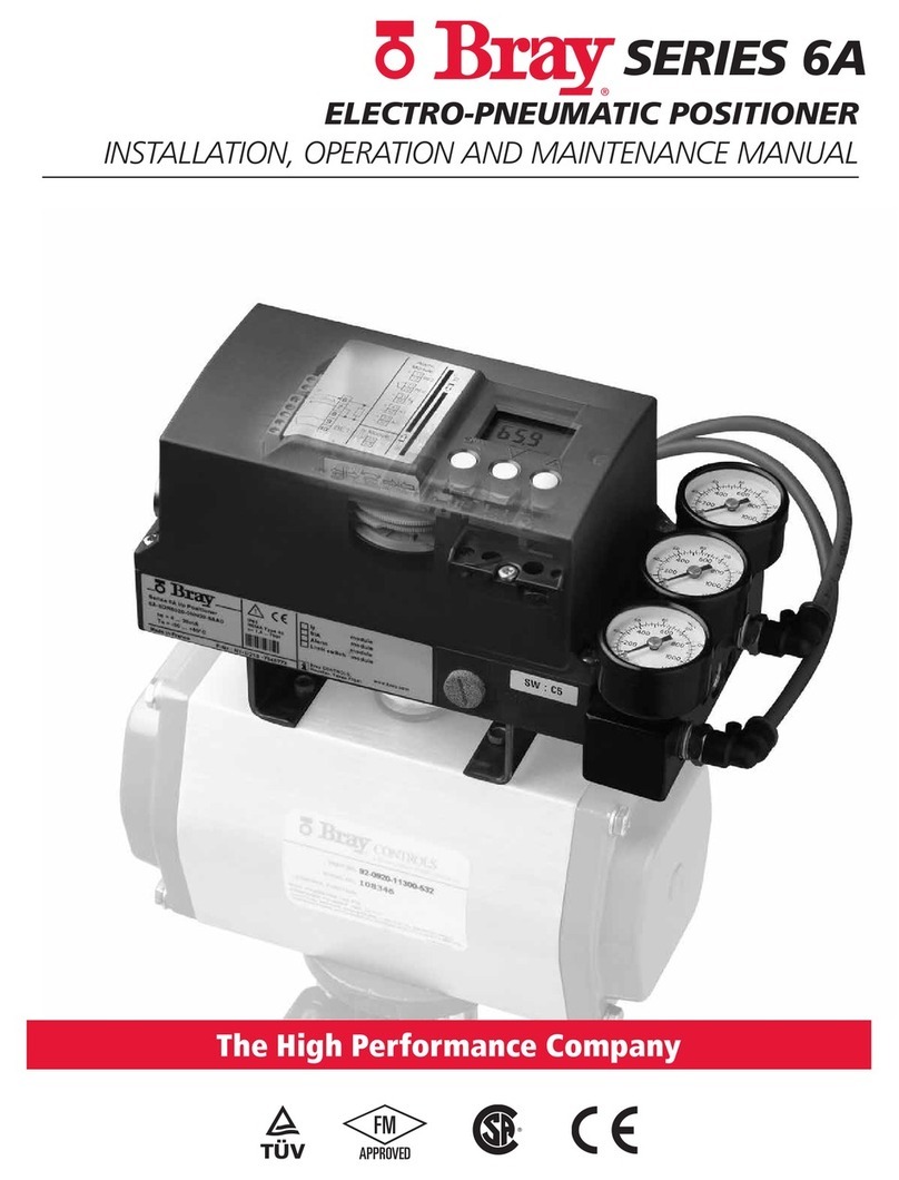
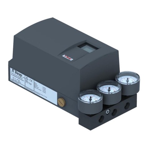
Bray 6A series User manual

SERIES 6A
SMART POSITIONER
ADVANCED SETUP GUIDE
BRAY.COM THE HIGH PERFORMANCE COMPANY
This document is not comprehensive, and is intended to help users become familiar with the Bray S6A
Electro-Pneumatic Positioner Advanced Setup & Diagnostics. For more detailed information please
reference the Installation, Operation and Maintenance Manual available on the Bray website.

2 of 52© 2021 BRAY INTERNATIONAL, INC. ALL RIGHTS RESERVED. BRAY.COM EN_TSM-2004-6A Advanced_Set-Up_20211012
SERIES 6A
ADVANCED SETUP GUIDE
CONTENTS
1.0 Device Components . . . . . . . . . . . . . . . . . . . . . . . . . . . . . . . . 3
2.0 Electrical Wiring. . . . . . . . . . . . . . . . . . . . . . . . . . . . . . . . . . . 5
3.0 Setup Parameter Overview. . . . . . . . . . . . . . . . . . . . . . . . . . . . . 11
4.0 Overview of Diagnostic Values . . . . . . . . . . . . . . . . . . . . . . . . . . 15
5.0 Overview of Diagnostic Parameters. . . . . . . . . . . . . . . . . . . . . . . .36
6.0 Diagnostics and Troubleshooting . . . . . . . . . . . . . . . . . . . . . . . . .39
7.0 Fail States . . . . . . . . . . . . . . . . . . . . . . . . . . . . . . . . . . . . . . 51

3 of 52© 2021 BRAY INTERNATIONAL, INC. ALL RIGHTS RESERVED. BRAY.COM EN_TSM-2004-6A Advanced_Set-Up_20211012
SERIES 6A
ADVANCED SETUP GUIDE
3.3 Device components
3.3.1 Overview of device components
: : r
r
P$
P$
%,1
r
r
Arrowhead means: Turn the device to see the corresponding view
①Wiring diagram on module cover ⑩Restrictor Y1 for double-acting actuators
②Display ⑪Exhaust air outlet with a sound absorber
③Output: Actuating pressure Y1 ⑫Transmission ratio selector2)
④Input: Supply pressure PZ ⑬Friction clutch adjustment wheel
⑤Output: Actuating pressure Y21) ⑭Basic electronics
⑥Purging air selector ⑮Connecting terminals of option modules
⑦Buttons ⑯Blanking plug
⑧Restrictor Y2 for double-acting actuators1) ⑰Cable gland
⑨Restrictor Y1 for single-acting actuators
1) for double-acting actuators
2) visible when the positioner is open
Figure 1 View of positioner with cover open
See also
Structure of pneumatic connection (Page 89)
Description
3.3 Device components
SIPART PS2 with 4 to 20 mA/HART
28 Operating Instructions, 10/2020, A5E00074631-AF
1.0 Device Components

4 of 52© 2021 BRAY INTERNATIONAL, INC. ALL RIGHTS RESERVED. BRAY.COM EN_TSM-2004-6A Advanced_Set-Up_20211012
SERIES 6A
ADVANCED SETUP GUIDE
-+
1
10
138
238 9
$$
$
$
①Display ⑧Output: Actuating pressure Y21)
②Restrictor Y1 ⑨Restrictor Y21)
③Output: Actuating pressure Y1 ⑩Buttons
④Input: Supply pressure PZ ⑪Ground terminal
⑤Safety catch ⑫Connecting terminals of option modules
⑥Transmission ratio selector2) ⑬Connecting terminals of basic electronics
⑦Friction clutch adjustment wheel
1) for double-acting actuators
2) visible when the positioner is open
Figure 2 View of positioner in f ameproof enclosure, cover opened
3.3.2 Basic electronics
Figure 3 Basic electronics, schematic representation
The basic electronics contains:
• CPU
• Memory
• Analog-to-digital converter
• Display
Description
3.3 Device components
SIPART PS2 with 4 to 20 mA/HART
Operating Instructions, 10/2020, A5E00074631-AF 29

5 of 52© 2021 BRAY INTERNATIONAL, INC. ALL RIGHTS RESERVED. BRAY.COM EN_TSM-2004-6A Advanced_Set-Up_20211012
SERIES 6A
ADVANCED SETUP GUIDE
Shield
Figure 4 Base plate ①
5.2 Electrical wiring
5.2.1 Electronics
+$57
①Setpoint 4 ... 20 mA, terminals 6 and 7
②Digital input DI1, terminals 9 and 10
③HART connection
Figure 5 Connection diagram for electronics 2-wire
Connection
5.2 Electrical wiring
SIPART PS2 with 4 to 20 mA/HART
Operating Instructions, 10/2020, A5E00074631-AF 79
2.0 Electrical Wiring

6 of 52© 2021 BRAY INTERNATIONAL, INC. ALL RIGHTS RESERVED. BRAY.COM EN_TSM-2004-6A Advanced_Set-Up_20211012
SERIES 6A
ADVANCED SETUP GUIDE
8
①Setpoint 4 ... 20 mA, terminals 3 and 8
②Digital input DI1, terminals 9 and 10
Figure 6 Connection diagram for electronics, 2/3/4-wire, with wiring con iguration 2-wire
8
①Power source 18 ... 30 V, terminals 2 and 4
②Setpoint 0/4 ... 20 mA, terminals 6 and 4
③Digital input DI1, terminals 9 and 10
Figure 7 Connection diagram for electronics, 2/3/4-wire, with wiring con iguration 3-wire
8
①Power source 18 ... 30 V, terminals 2 and 4
②Setpoint 0/4 ... 20 mA, terminals 6 and 8
③Digital input DI1
Figure 8 Connection diagram for electronics, 2/3/4-wire, with wiring con iguration 4-wire
Connection
5.2 Electrical wiring
SIPART PS2 with 4 to 20 mA/HART
80 Operating Instructions, 10/2020, A5E00074631-AF

7 of 52© 2021 BRAY INTERNATIONAL, INC. ALL RIGHTS RESERVED. BRAY.COM EN_TSM-2004-6A Advanced_Set-Up_20211012
SERIES 6A
ADVANCED SETUP GUIDE
5.2.2 Split range
①Positioner 1
②Positioner 2
③Signal source 0/4 ... 20 mA, terminals 6 and 8
④Power source 18 ... 30 V, terminals 2 and 8
Figure 9 Series connection of 2 positioners, e.g. split range
Connection
5.2 Electrical wiring
SIPART PS2 with 4 to 20 mA/HART
Operating Instructions, 10/2020, A5E00074631-AF 81

8 of 52© 2021 BRAY INTERNATIONAL, INC. ALL RIGHTS RESERVED. BRAY.COM EN_TSM-2004-6A Advanced_Set-Up_20211012
SERIES 6A
ADVANCED SETUP GUIDE
5.2.3 Option modules
5.2.3.1 Digital I/O Module (DIO) 6DR4004-6A / -8A
①Digital input DI2, electrically isolated ④Digital output DO1
②Digital input DI2, dry contact ⑤Digital output DO2
③Fault message output
Figure 10 Digital I/O Module (DIO)
5.2.3.2 Analog Output Module (AOM) 6DR4004-6J / -8J
①Analog output AO
Figure 11 Analog Output Module (AOM)
5.2.3.3 Inductive Limit Switches (ILS) 6DR4004-6G / -8G
①Fault message output, has no function in combination with 6DR4004-3ES
②Digital output (limit monitor) A1
③Digital output (limit monitor) A2
Connection
5.2 Electrical wiring
SIPART PS2 with 4 to 20 mA/HART
82 Operating Instructions, 10/2020, A5E00074631-AF
Figure 12 Inductive Limit Switches (ILS)

9 of 52© 2021 BRAY INTERNATIONAL, INC. ALL RIGHTS RESERVED. BRAY.COM EN_TSM-2004-6A Advanced_Set-Up_20211012
SERIES 6A
ADVANCED SETUP GUIDE
Figure 5-9 Inductive Limit Switches (ILS)
5.2.3.4 Mechanical Limit Switches (MLS) 6DR4004-6K / -8K
DANGER
Supply with hazardous voltage
If you connect the switching contacts of the 6DR4004-8K module to a hazardous voltage,
observe the following safety rules:
1. Isolate the device from power. Use a circuit breaker positioned near the device to do this.
2. Make sure that the device cannot be switched back on inadvertently.
3. Make sure the device is truly isolated from power.
CAUTION
Maximum AC/DC switching voltage with UL approval E344532
Mechanic Limit Switches (MLS) 6DR4004-6K/-8K
are approved for use with positioners with UL
approval. The maximum switching voltage in this case is ≤ 30 V AC/DC.
If switching voltages greater than 30 V are connected, the UL approval for the positioner
becomes invalid.
Connection diagram Mechanic Limit Switches (MLS) 6DR4004-6K and -8K
①Fault message output, has no function in combination with 6DR4004-4ES
②Digital output (limit monitor) A1
③Digital output (limit monitor) A2
Figure 5-10 Mechanic Limit Switches (MLS)
Procedure
1. Loosen the screw ① on the transparent cover ②.
2. Pull the transparent cover ② up to the front end stop.
3. Tighten every cable in the corresponding terminal.
Connection
5.2 Electrical wiring
SIPART PS2 with 4 to 20 mA/HART
Operating Instructions, 10/2020, A5E00074631-AF 83
Figure 13

10 of 52© 2021 BRAY INTERNATIONAL, INC. ALL RIGHTS RESERVED. BRAY.COM EN_TSM-2004-6A Advanced_Set-Up_20211012
SERIES 6A
ADVANCED SETUP GUIDE
4. Slide the transparent cover ② up to the end stop of the basic electronics.
5. Tighten the screw ① of the transparent cover ②.
6. Connect the cables of each switch to the lug of the printed circuit board in pairs. Use the
provided cable ties ③ for this purpose.
①Screw
②Cover
③Cable tie
Figure 5-11 Connecting the cables
Connection
5.2 Electrical wiring
SIPART PS2 with 4 to 20 mA/HART
84 Operating Instructions, 10/2020, A5E00074631-AF
Figure 14

11 of 52© 2021 BRAY INTERNATIONAL, INC. ALL RIGHTS RESERVED. BRAY.COM EN_TSM-2004-6A Advanced_Set-Up_20211012
SERIES 6A
ADVANCED SETUP GUIDE
8.3 Parameter overview
Parameter Function Parameter values Unit
1.YFCT Type of actuator Normal Inverted
Part-turn actuator turn -turn
Linear actuator WAY -WAY
Linear actuator - carrier pin on actuator spindle FWAY -FWAY
Linear actuator - external linear potentiometer
(e.g. with cylinder drives)
LWAY -LWAY
Part-turn actuator with NCS/iNCS ncSt -ncSt
Linear actuator with NCS ncSL -ncSL
Linear actuator with NCS/iNCS and lever ncSLL -ncLL
2.YAGL Rated angle of rotation of positioner shaft1)
33° Degrees
90°
3.YWAY 2) Range of stroke (optional setting) 3)
OFF mm
5 | 10 | 15 | 20
(Short lever 33°, range of stroke
5 to 20 mm)
25 | 30 | 35
(Short lever 90°, range of stroke
25 to 35 mm)
40 | 50 | 60 | 70 | 90 | 110 | 130
(Long lever 90°, range of stroke
40 to 130 mm)
4.INITA Initialization (automatic) NOINI | no / ###.# | Strt
5.INITM Initialization (manual) NOINI | no / ###.# | Strt
6.SCUR Current range of setpoint
0 ... 20 mA 0 mA
4 ... 20 mA 4 mA
7.SDIR Setpoint direction
Rising riSE
Falling FALL
8.SPRA Setpoint split range start 0.0 ... 100.0 %
9.SPRE Setpoint split range end 0.0 ... 100.0 %
10.TSUP Setpoint ramp up Auto / 0 ... 400 s
11.TSDO Setpoint ramp down 0 ... 400 s
Parameter assignment
8.3 Parameter overview
SIPART PS2 with 4 to 20 mA/HART
134 Operating Instructions, 10/2020, A5E00074631-AF
3.0 Setup Parameter Overview

12 of 52© 2021 BRAY INTERNATIONAL, INC. ALL RIGHTS RESERVED. BRAY.COM EN_TSM-2004-6A Advanced_Set-Up_20211012
SERIES 6A
ADVANCED SETUP GUIDE
Parameter Function Parameter values Unit
12.SFCT Setpoint function
Linear LIN
Equal percentage 1 : 25 1 - 25
1 : 33 1 - 13
1 : 50 1 - 50
Inverse equal percentage 25 : 1 n1 - 25
33 : 1 n1 - 33
50 : 1 n1 - 50
Freely adjustable FrEE
13.SLO ...
33.SL20 4)
Setpoint turning point at
13.SL0 0 % 0.0 ... 100.0 %
14.SL1 ... 5 %
32.SL19 95 %
33.SL20 100 %
34.DEBA Deadband of closed-loop controller Auto / 0.1 ... 10.0 %
35.YA Start of the manipulated variable limit 0.0 ... 100.0 %
36.YE End of the manipulated variable limit 0.0 ... 100.0 %
37.YNRM Standardization of manipulated variable
To mechanical travel MPOS
To ow FLoW
38.YDIR Direction of action of manipulated variable for display and position feedback
Rising riSE
Falling FALL
39.YCLS Tight closing / fast closing with manipulated variable
None no
Tight closing Up uP
Tight closing Down do
Tight closing Up and Down up do
Fast closing Up Fu
Fast closing Down Fd
Fast closing Up and Down Fu Fd
Tight closing Up and fast closing Down uP Fd
Fast closing Up and tight closing Down Fu do
40.YCDO Lower value for fast closing / tight closing 0.0 ... 0.5 ... 100.0 %
41.YCUP Upper value for fast closing / tight closing 0.0 ... 99.5 ... 100.0 %
Parameter assignment
8.3 Parameter overview
SIPART PS2 with 4 to 20 mA/HART
Operating Instructions, 10/2020, A5E00074631-AF 135

13 of 52© 2021 BRAY INTERNATIONAL, INC. ALL RIGHTS RESERVED. BRAY.COM EN_TSM-2004-6A Advanced_Set-Up_20211012
SERIES 6A
ADVANCED SETUP GUIDE
Parameter Function Parameter values Unit
42.DI1 5)) Function digital input DI1 NO contact NC contact
None OFF
Message only on -on
Block conguration bLoc1
Block conguring and manual operation bLoc2
Move process valve to position YE uP -uP
Move process valve to position YA doWn -doWn
Block movement StoP -StoP
Partial Stroke Test PSt -PSt
43.DI2 5) Function digital input DI2 NO contact NC contact
None OFF
Message only on -on
Move process valve to position YE uP -uP
Move process valve to position YA doWn -doWn
Block movement StoP -StoP
Partial Stroke Test PSt -PSt
44.AFCT 6) Alarm function Normal Inverted
None OFF
A1 = Min, A2 = Max
A1 = Min, A2 = Min
A1 = Max, A2 = Max
45.A1 Response threshold, alarm 1 0.0 ... 10.0 ... 100.0 %
46.A2 Response threshold, alarm 2 0.0 ... 90.0 ... 100.0 %
47. FCT 6) Function of fault message output Normal Inverted
Fault
Fault + not automatic 7)
Fault + not automatic + DI 7)
48. TIM Monitoring period for setting of fault message
'Control deviation'
Auto / 0 ... 100 s
49. LIM Response threshold for fault message 'Control
deviation'
Auto / 0 ... 100 %
50.PRST Preset
Reset all parameters which can be reset by "Init",
"PArA" and "diAg".
ALL
Reset parameters 'YFCT' to 'INITM'. Init
Reset parameters 'SCUR' to 'LIM'. PArA
Reset parameters A to U of the extended diagnostics
function as well as parameter 'XDIAG'.
diAg
51.PNEUM Pneumatics type
Standard pneumatic block Std
Fail in Place pneumatic block FIP
Operation with boosters booSt
Parameter assignment
8.3 Parameter overview
SIPART PS2 with 4 to 20 mA/HART
136 Operating Instructions, 10/2020, A5E00074631-AF

14 of 52© 2021 BRAY INTERNATIONAL, INC. ALL RIGHTS RESERVED. BRAY.COM EN_TSM-2004-6A Advanced_Set-Up_20211012
SERIES 6A
ADVANCED SETUP GUIDE
Parameter Function Parameter values Unit
52.XDIAG Activation of extended diagnostics
O OFF
Single stage message On1
Two stage message On2
Three stage message On3
1) Set transmission ratio selector accordingly.
2) Parameter only appears with "WAY", "-WAY", "ncSLL" and "-NCLL"
3)
If used, the value on the actuator must correspond to the set range of stroke on the lever arm. Carrier must be set to the value
of the actuator travel or, if this value is not scaled, to the next higher scaled value.
4) Setpoint turning points only appear when '12.SFCT = FrEE' is selected.
5) NO contact: Action when signal state is 1; NC contact: Action when signal state is 0
6) Normal: conductive, no fault; Inverted: deactivated, fault
7) '+' means: OR logic operation
Parameter assignment
8.3 Parameter overview
SIPART PS2 with 4 to 20 mA/HART
Operating Instructions, 10/2020, A5E00074631-AF 137

15 of 52© 2021 BRAY INTERNATIONAL, INC. ALL RIGHTS RESERVED. BRAY.COM EN_TSM-2004-6A Advanced_Set-Up_20211012
SERIES 6A
ADVANCED SETUP GUIDE
Overview of diagnostics values
No. Short desig‐
nation
Meaning Representable di‐
agnostics values
Unit Properties
1 STRKS Number of total strokes 0 ... 4.29E9 - ①
2 CHDIR Number of changes in direction 0 ... 4.29E9 - ①
3 CNT Number of fault messages 0 ... 4.29E9 - ①
4 A1CNT Number of alarms 1 0 ... 4.29E9 - ①
5 A2CNT Number of alarms 2 0 ... 4.29E9 - ①
6 HOURS Number of operating hours 0 ... 4.29E9 Hours ②
7 HOURR Resettable operating hours counter 0 ... 4.29E9 ①
8WAY Determined travel 0 ... 130 mm or ° ②
9 TUP Travel time up 0.0 / 0 ... 1000 s ②
10 TDOWN Travel time down 0.0 / 0 ... 1000 s ②
11 LEAK Leakage test - / 0.0 ... 100.0 %/minute ③
12 PST Monitoring of Partial Stroke Test OFF / ###.#, FdIni,
notSt, SdtSt, fdtSt,
notoL, Strt, StoP
s for ###.# ③
13 PRPST Time since last Partial Stroke Test ###, notSt, Sdtst,
fdtSt
Days ②
14 NXPST Time until next Partial Stroke Test OFF / ### Days ②
15 DEVI Dynamic control valve behavior 0.0 ... 100.0 % ②
16 ONLK Pneumatic leakage 0.0 ... 100.0 - ②
17 STIC Stiction (slipstick) 0.0 ... 100.0 % ②
18 ZERO Lower endstop 0.0 ... 100.0 % ②
19 OPEN Upper endstop 0.0 ... 100.0 % ②
20 PAVG Average value of position OFF, IdLE, rEF,
COMP
0.0 ... 100.0
%②
21 P0 Potentiometer value of lower endstop (0%) 0.0 ... 100.0 % ③
22 P100 Potentiometer value of upper endstop (100%) 0.0 ... 100.0 % ③
23 IMPUP Pulse length up 6 ... 160 ms ④
24 IMPDN Pulse length down 6 ... 160 ms ④
25 PAUTP Pulse pause 2 ... 28 ... 320 ms ④
26 DBUP Deadband up 0.1 ... 10.0 % ②
27 DBDN Deadband down 0.1 ... 10.0 % ②
28 SSUP Slow step zone up 0.1 ... 10.0 ...
100.0
%④
29 SSDN Slow step zone down 0.1 ... 10.0 ...
100.0
%④
30 TEMP Current temperature -50 ... 100
-58 ... 212
°C
°F
②
31 TMIN Minimum temperature (min/max pointer) -50 ... 100
-58 ... 212
°C
°F
②
32 TMAX Maximum temperature (min/max pointer) -50 ... 100
-58 ... 212
°C
°F
②
Diagnostics and troubleshooting
11.2 Diagnostics
SIPART PS2 with 4 to 20 mA/HART
216 Operating Instructions, 10/2020, A5E00074631-AF
4.0 Overview of Diagnostic Values

16 of 52© 2021 BRAY INTERNATIONAL, INC. ALL RIGHTS RESERVED. BRAY.COM EN_TSM-2004-6A Advanced_Set-Up_20211012
SERIES 6A
ADVANCED SETUP GUIDE
No. Short desig‐
nation
Meaning Representable di‐
agnostics values
Unit Properties
33 T1 Number of operating hours in temperature range 1 0 ... 4.29E9 Hours ②
34 T2 Number of operating hours in temperature range 2 0 ... 4.29E9 Hours ②
35 T3 Number of operating hours in temperature range 3 0 ... 4.29E9 Hours ②
36 T4 Number of operating hours in temperature range 4 0 ... 4.29E9 Hours ②
37 T5 Number of operating hours in temperature range 5 0 ... 4.29E9 Hours ②
38 T6 Number of operating hours in temperature range 6 0 ... 4.29E9 Hours ②
39 T7 Number of operating hours in temperature range 7 0 ... 4.29E9 Hours ②
40 T8 Number of operating hours in temperature range 8 0 ... 4.29E9 Hours ②
41 T9 Number of operating hours in temperature range 9 0 ... 4.29E9 Hours ②
42 VENT1 Number of switching cycles of pneumatic block, valve
1
0 ... 4.29E9 - ②
43 VENT2 Number of switching cycles of pneumatic block, valve
2
0 ... 4.29E9 - ②
44 VEN1R Number of switching cycles of pneumatic block, valve
1, resettable
0 ... 4.29E9 - ①
45 VEN2R Number of switching cycles of pneumatic block, valve
2, resettable
0 ... 4.29E9 - ①
46 STORE Save the current values as 'last maintenance' (press
button for 5 seconds)
- - ③
47 PRUP Prediction up 1 ... 40 - ④
48 PRDN Prediction down 1 ... 40 - ④
49 WT00 Number of operating hours in the travel range WT00 0 ... 4.29E9 Hours ①
50 WT05 Number of operating hours in the travel range WT05 0 ... 4.29E9 Hours ①
51 WT10 Number of operating hours in the travel range WT10 0 ... 4.29E9 Hours ①
52 WT30 Number of operating hours in the travel range WT30 0 ... 4.29E9 Hours ①
53 WT50 Number of operating hours in the travel range WT50 0 ... 4.29E9 Hours ①
54 WT70 Number of operating hours in the travel range WT70 0 ... 4.29E9 Hours ①
55 WT90 Number of operating hours in the travel range WT90 0 ... 4.29E9 Hours ①
56 WT95 Number of operating hours in the travel range WT95 0 ... 4.29E9 Hours ①
57 LKPUL Length of the leakage compensation pulse -256 ... 0 ... 254 ms ②
58 LKPER Period of the leakage compensation pulse 0.00 ... 600.00 s ②
59 mA Setpoint current 0.0 ... 20.0 mA ②
60 PZ Supply pressure PZ 9.999
999.99
9.999
bar
psi
MPa
③
61 P1 Actuating pressure Y1 ③
62 P2 Actuating pressure Y2 ③
63 PZMAX Maximum supply pressure PZ ①
64 N_MIN Event counter violations of lower limit PZ 0 ... 99999
-
①
65 N_MAX Event counter violations of upper limit PZ
66 N1MAX Event counter violations limit Y1
Diagnostics and troubleshooting
11.2 Diagnostics
SIPART PS2 with 4 to 20 mA/HART
Operating Instructions, 10/2020, A5E00074631-AF 217

17 of 52© 2021 BRAY INTERNATIONAL, INC. ALL RIGHTS RESERVED. BRAY.COM EN_TSM-2004-6A Advanced_Set-Up_20211012
SERIES 6A
ADVANCED SETUP GUIDE
67 LMY1 +/- Leakage at Y1 ±0.000 ... 9.999
±0.000 ... 0.999
±0.00 ... 99.99
bar / min
MPa / min
psi / min
②
68 LMY2 +/- Leakage at Y2
69 LMUY1 Maximum positive leakage at Y1 +0.000 ... 9.999
+0.000 ... 0.999
+0.00 ... 99.99
bar / min
MPa / min
psi / min
①
70 LMUY2 Maximum positive leakage at Y2
71 LMDY1 Maximum negative leakage at Y1 -9.999 ... -0.000
-0.999 ... -0.000
-99.99 ... -0.000
bar / min
MPa / min
psi / min
①
72 LMDY2 Maximum negative leakage at Y2
11.2.4 Meaning of the diagnostics values
11.2.4.1 Diagnostic value '1.STRKS - Number of total strokes'
Display range: 0 ... 4.29E9
Purpose: In operation, the movements of the actuator are summed up and
displayed in this diagnostics parameter as the number of strokes.
Unit: 100% strokes, i.e. the path between 0% and 100% and back.
11.2.4.2 Diagnostic value '2.CHDIR - Number of changes in direction'
Display range: 0 ... 4.29E9
Purpose: Every change in direction of the actuator is noted in the controller
and added to the number of changes in direction.
11.2.4.3 Diagnostic value '3.\\CNT - Number of fault messages'
Display range: 0 ... 4.29E9
Purpose: Every fault is noted in the closed-loop controller with '3. CNT' and
added to the number of fault messages.
11.2.4.4 Diagnostic value '4.A1CNT - Number of alarms 1' / '5.A2CNT - Number of alarms 2'
Requirement: '44.AFCT' Alarm function (Page 154) parameter is activated.
Display range: 0 ... 4.29E9
Purpose: This value indicates how often the alarm has been triggered.
Diagnostics and troubleshooting
11.2 Diagnostics
SIPART PS2 with 4 to 20 mA/HART
218 Operating Instructions, 10/2020, A5E00074631-AF

18 of 52© 2021 BRAY INTERNATIONAL, INC. ALL RIGHTS RESERVED. BRAY.COM EN_TSM-2004-6A Advanced_Set-Up_20211012
SERIES 6A
ADVANCED SETUP GUIDE
11.2.4.5 Diagnostic value '6.HOURS - Number of operating hours'
Display range: 0 ... 4.29E9
Purpose: The runtime meter is incremented every hour as soon as electric
auxiliary power is supplied to the positioner.
11.2.4.6 Diagnostic value '7.HOURR - Resettable operating hours counter'
Display range:
Purpose:
Description:
0 ... 4.29E9
The runtime meter is incremented every hour as soon as electric
auxiliary power is supplied to the positioner. In contrast to
Diagnos‐tic value '6.HOURS - Number of operating hours', this
value can be reset.
In order to minimize the control valve wear resulting from a poor
control quality, it makes sense to optimize the positioner's parame‐
ters. You can recognize optimum parameter settings when the val‐
ues of the Diagnostic value '44.VEN1R' / '45.VEN2R' are low. Low
values mean that the switching frequency of the positioner
pneumatics is also low. In order to carry out a comparison with var‐
ious parameter settings, determine the number of switching cycles
per hour. To do this, use the values of the Diagnostic value
'44.VEN1R' / '45.VEN2R' and '7.HOURR'. These three parameters
can be reset to enable simpler determination of the values.
11.2.4.7 Diagnostic value '8.WAY - Determined travel'
Condition for
linear actuator:
Display range:
Purpose:
The travel is set in the '3.YWAY' Range of stroke parameter.
0 ... 130
This value in mm or ° speci ies the travel determined during the
initialization.
11.2.4.8 Diagnostic value '9.TUP - Travel time up' / '10.TDOWN - Travel time down'
Display range: 0 ... 1000
Purpose: This value indicates the current UP or DOWN travel time in seconds
determined during the initialization.
Diagnostics and troubleshooting
11.2 Diagnostics
SIPART PS2 with 4 to 20 mA/HART
Operating Instructions, 10/2020, A5E00074631-AF 219

19 of 52© 2021 BRAY INTERNATIONAL, INC. ALL RIGHTS RESERVED. BRAY.COM EN_TSM-2004-6A Advanced_Set-Up_20211012
SERIES 6A
ADVANCED SETUP GUIDE
11.2.4.9 Diagnostic value '11.LEAK - Leakage test'
Condition The positioner is initialized and in manual mode (MAN).
Display range: •-
• 0.0 ... 100.0
Purpose: You can use this diagnostics parameter to read the last test result or
start an oine leakage test with which you can detect leakages in
the actuator or in the pipe installation. Display is percent stroke per
minute referred to the total stroke. A test result originates from one
of the following options:
• Function '11.LEAK' has already been carried out.
• Leakage test was already carried out during initialization.
• 'Oine leakage test' function was already executed by a HOST
system.
"-" in the display can have the following causes:
• A leakage test has not yet been carried out.
• Resetting to the factory settings was carried out using
the '50.PRST' Preset > ALL parameter.
• Positioner is not initialized.
How to start the test
1. Move the actuator to the position at which you wish to start the
test.
2. In 'Diagnostics' mode, go to the '11.LEAK' diagnostic value as
described in section Display of diagnostics values.
3. Start the function by pressing the button for at least 5 seconds.
Description: 'Strt' is output in the display. The function is started after 5 seconds.
'tESt' and the current position of the actuator (actual value) are then
displayed alternately for one minute.
After one minute, the display shows the dierence in the actuator
position before and after the test. This means: the actuator position
has changed by the displayed value in one minute.
Diagnostics and troubleshooting
11.2 Diagnostics
SIPART PS2 with 4 to 20 mA/HART
220 Operating Instructions, 10/2020, A5E00074631-AF

20 of 52© 2021 BRAY INTERNATIONAL, INC. ALL RIGHTS RESERVED. BRAY.COM EN_TSM-2004-6A Advanced_Set-Up_20211012
SERIES 6A
ADVANCED SETUP GUIDE
11.2.4.10 Diagnostic value '12.PST - Monitoring of Partial Stroke Test'
Indication on the display: • OFF
• C-ERR
• FdIni
• notSt
• ###.#
• SdtSt
• FdtSt
Purpose: This diagnostics parameter indicates the measured stroke time of
the last Partial Stroke Test.
A Partial Stroke Test can be initiated manually or an active Partial
Stroke Test can be interrupted by pressing the button.
Description of indications
on the display:
• OFF: The Partial Stroke Test function is deactivated.
• C-ERR: Conguration error. Partial Stroke Test cannot be started.
Settings in the 'A1.STPOS start position', 'A3.STRKH stroke height'
and 'A4.STRKD stroke direction' are not plausible.
• FdIni - Failed PST Initialization: The reference stroke time meas‐
urement of the Partial Stroke Test has failed.
• notSt - No Test: A Partial Stroke Test has not yet been executed.
• ###.#: Corresponds to the measured stroke time in seconds. The
last Partial Stroke Test was successfully executed.
• SdtSt - Stopped Test: The last Partial Stroke Test was interrupted.
• FdtSt - Failed Test: The last Partial Stroke Test failed.
Status messages: The following status messages appear when you hold the button
pressed:
•
notoL - No Tolerance: The valve is outside the tolerance range for
start of the Partial Stroke Test. No manual Partial Stroke Test will
be started.
•
Strt - Start: A manual Partial Stroke Test is started after the button
is pressed for ve seconds.
• WAIt - Wait: The Partial Stroke Test is being executed.
Factory setting: OFF
Diagnostics and troubleshooting
11.2 Diagnostics
SIPART PS2 with 4 to 20 mA/HART
Operating Instructions, 10/2020, A5E00074631-AF 221
Other manuals for 6A series
3
Table of contents
Other Bray Valve Positioner manuals
Popular Valve Positioner manuals by other brands

ABB
ABB TZIDC manual
Samson
Samson TROVIS SAFE 3730 Series operating instructions
RTK
RTK RE3447 Series Installation and operating instructions
GF
GF SPC operating instructions
Samson
Samson Type 3766 Mounting and operating instructions
Spirax Sarco
Spirax Sarco SP7-10 Installation and maintenance instructions
Fisher
Fisher 3582 instruction manual

Parker
Parker 404XE Series product manual
Lang
Lang LHT500 Assembly instruction
Flowserve
Flowserve Logix 500 Series Installation, operation & maintenance instructions

Samson
Samson 3725 series Mounting and operating instructions
tissin
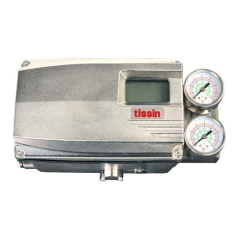
tissin TS800 Series instruction manual

