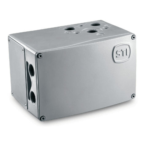
Bray Flow-Tek FTG Series User manual

FLOW-TEK FTG SERIES
MANUAL GEAR OPERATOR
Installation Operation and Maintenance Manual
BRAY.COM THE HIGH PERFORMANCE COMPANY

FLOW-TEK FTG SERIES
MANUAL GEAR OPERATOR
Installation, Operation, and Maintenance Manual
2 of 11© BRAY INTERNATIONAL INC ALL RIGHTS RESERVED BRAYCOM The Information
contained herein shall not be copied transferred conveyed or displayed in any manner that would
violate its proprietary nature without the express written permission of Bray International Inc
CONTENTS
DEFINITION OF TERMS . . . . . . . . . . . . . . . . . . . . . . . . . . . . . . . . . . . . . . . . . . . . . . . .
INTRODUCTION . . . . . . . . . . . . . . . . . . . . . . . . . . . . . . . . . . . . . . . . . . . . . . . . . . . .
INSTALLATION . . . . . . . . . . . . . . . . . . . . . . . . . . . . . . . . . . . . . . . . . . . . . . . . . . . . .
OPERATION AND TRAVEL STOP ADJUSTMENT . . . . . . . . . . . . . . . . . . . . . . . . . . . . . . . . . .
GEAR LUBRICATION . . . . . . . . . . . . . . . . . . . . . . . . . . . . . . . . . . . . . . . . . . . . . . . .

FLOW-TEK FTG SERIES
MANUAL GEAR OPERATOR
Installation, Operation, and Maintenance Manual
3 of 11© BRAY INTERNATIONAL INC ALL RIGHTS RESERVED BRAYCOM The Information
contained herein shall not be copied transferred conveyed or displayed in any manner that would
violate its proprietary nature without the express written permission of Bray International Inc
DEFINITION OF TERMS
All information within this manual is relevant to the safe operation
and proper care of your FTG Series Manual Gear Operator
Please understand the following examples of information used
throughout this manual
DANGER
Indicates a potentially hazardous situation which if not avoided
will result in death or serious injury
WARNING
Indicates a potentially hazardous situation which if not avoided
could result in death or serious injury
CAUTION
Indicates a potentially hazardous situation which if not avoided
could result in minor or moderate injury
NOTICE
Used without the safety alert symbol indicates a potential
situation which if not avoided may result in an undesirable result
or state including property damage
READ AND FOLLOW THESE INSTRUCTIONS CAREFULLY
SAVE THIS MANUAL FOR FUTURE USE

FLOW-TEK FTG SERIES
MANUAL GEAR OPERATOR
Installation, Operation, and Maintenance Manual
4 of 11© BRAY INTERNATIONAL INC ALL RIGHTS RESERVED BRAYCOM The Information
contained herein shall not be copied transferred conveyed or displayed in any manner that would
violate its proprietary nature without the express written permission of Bray International Inc
INTRODUCTION
Flow-Tek’s FTG Series Manual Gear Operators were designed to
handle the toughest applications and provide years of trouble-
free service and reliability
The FTG Series gear operators feature a ductile iron housing
aluminum bronze gear segment and one-piece steel worm gear
input shaft with tapered roller bearings on both ends
Adjustable travel stops provide precise adjustment in both open
and closed positions
Weather proof seal caps ensure travel stop adjustment is
operational through harsh environmental conditions
The gears are self-locking and able to hold any position
necessary The gear housings are sealed and weatherproof to
fully isolate internal parts from atmospheric conditions
External locking devices readily avaiable
Features include a readily accessible hand-wheel position
indicator ISO mounting pattern and mechanical travel
stops which permit field adjustment of valve position as required
WARNING
Gear operator handwheel is attached to input shaft with pin The
gear operator with or without valve should never be lifted by
handwheel as that can lead to mechanical damage of the pin
input shaft housing and or worm gear

FLOW-TEK FTG SERIES
MANUAL GEAR OPERATOR
Installation, Operation, and Maintenance Manual
5 of 11© BRAY INTERNATIONAL INC ALL RIGHTS RESERVED BRAYCOM The Information
contained herein shall not be copied transferred conveyed or displayed in any manner that would
violate its proprietary nature without the express written permission of Bray International Inc
INSTALLATION
For direct mount skip bracket coupler installation and proceed
with mounting studs installation
Insert mounting coupler into the gear and manually operate the
gear operator until coupler machined area is in line with valve
stem
Remove coupler from the gear
Install mounting bracket as required using valve mounting plate
and supplied fasteners It is recommended to use a small amount
of Anti-seize on the threads during assembly Fasten bracket
loosely
Place mounting coupler onto the valve stem It is recommended
that a small amount of lubricant or Anti-seize is applied to the
stem adaptor at both connections – to the valve stem and to the
gear operator
Install the mounting studs into the gear unit mounting holes
Carefully lower the gear unit over valve stem or stem adaptor
Make sure that the mounting studs are aligned with the holes
on the valve top mounting plate or with the top holes on the
bracket
WARNING
Do not place fingers or hand between gear operator and
mounting plate during installation as this is a pinch point
Tighten both gear nuts and bracket fasteners Ensure that the
gear is centrally mounted on the valve stemcoupler

FLOW-TEK FTG SERIES
MANUAL GEAR OPERATOR
Installation, Operation, and Maintenance Manual
6 of 11© BRAY INTERNATIONAL INC ALL RIGHTS RESERVED BRAYCOM The Information
contained herein shall not be copied transferred conveyed or displayed in any manner that would
violate its proprietary nature without the express written permission of Bray International Inc
OPERATION AND TRAVEL STOP ADJUSTMENT
To close the valve rotate the gear handwheel clockwise (right)
To open the valve rotate the gear handwheel counterclockwise
(left) The position indicator bolted to the rotating gear indicates
the valve position and moves as handwheel is turned
NOTICE
Position Indicator of the gear is for reference It is not calibrated
to show exact position
Image - Indicator Plate
Image shows the position indicator plate A clockwise rotation
(Right) of the gear input shaft will move the indicator arrow
clockwise towards the “SHUT” marking and closed position stop
(position shown in Image )
A counterclockwise rotation (Left) of the gear input shaft will
move the indicator arrow counterclockwise towards the “OPEN”
marking and open position stop
Position
Indicator

FLOW-TEK FTG SERIES
MANUAL GEAR OPERATOR
Installation, Operation, and Maintenance Manual
7 of 11© BRAY INTERNATIONAL INC ALL RIGHTS RESERVED BRAYCOM The Information
contained herein shall not be copied transferred conveyed or displayed in any manner that would
violate its proprietary nature without the express written permission of Bray International Inc
Image - Heavy Hex Counter Nuts
Image - Buna Weather Seal Caps
The gear stops consist of hex socket adjustment studs and heavy
hex counter nuts shown in Image They are protected by Buna
weather seal caps shown in Image
Gears mounted at the factory are shipped fully set and no
adjustment is needed If the gear has been removed replaced or
the integrity of the stops have been aected both stops shall be
re-adjusted
Tools needed to adjust gear stops
Adjustable or combination wrench
Allen hex wrench set
Setting the stops with valve mounted in line
Once gear is mounted remove seal caps (Image ) and position
indicator (Image )
For a gear mounted with the valve in the closed position
Loosen counter nut while holding the adjustment stop stud
with Allen wrench (Image )
Loosen adjustment stop stud by turning counterclockwise
Hex Socket
Adjustment
Stud
Seal
Cap
Hex
Counter
Nut

FLOW-TEK FTG SERIES
MANUAL GEAR OPERATOR
Installation, Operation, and Maintenance Manual
8 of 11© BRAY INTERNATIONAL INC ALL RIGHTS RESERVED BRAYCOM The Information
contained herein shall not be copied transferred conveyed or displayed in any manner that would
violate its proprietary nature without the express written permission of Bray International Inc
Image - Gear Stem Nut
Remove the indicator plate by removing the screws that are
securing it to the top of the gear Check position of gear stem
nut (Image ) The stem nut is machined with two concentric
squares with a degree oset angle
If flats of the stem nut squares are not parrallelperpendicular
to the valve bore adjust the position by turning handheel as
needed
Once the position of the stem nut is set drive the adjustment
stop stud by hand until feeling resistance
While holding adjustment stop stud with Allen wrench in
position tighten the counter nut Do not allow the adjustment
stop stud to move
Using the handwheel turn the valve to be - degrees
unseated and close again The gear should stop at set position
where the stem nut squares are parrallelperpendicular to flow
bore If not repeat adjustment steps
Repeat these steps for setting the stops for the fully open
position
Setting stops with valve on work bench
Start setting gear stops in the fully open position
Loosen counter nut while holding the adjustment stop stud
with Allen wrench (Image )
Loosen the adjustment stop stud by turning counterclockwise
Fully open valve Check position of the ball by looking through
the end of the valve bore If not fully open adjust position by
turning handwheel accordingly
Once fully open position is set tighten the adjustment stop
stud by hand until feeling resistance
While holding the adjustment stop stud with Allen wrench
in position tighten the counter hex nut Do not allow the
adjustment stop stud to move

FLOW-TEK FTG SERIES
MANUAL GEAR OPERATOR
Installation, Operation, and Maintenance Manual
9 of 11© BRAY INTERNATIONAL INC ALL RIGHTS RESERVED BRAYCOM The Information
contained herein shall not be copied transferred conveyed or displayed in any manner that would
violate its proprietary nature without the express written permission of Bray International Inc
Using handwheel turn the valve to be - degrees unseated
and then open again The gear should stop at set position
where ball bore is aligned with the seat inner diameter and
valve bore
For fully closed position loosen the counter nut while holding
the adjustment stop stud with Allen wrench (Image )
Loosen the adjustment stop stud by turning counterclockwise
Start closing the valve by rotating handwheel clockwise Stop
when the machined square of the gear stem nut rotates
degrees and mark the position
Tighten the adjustment stop stud by hand until feeling
resistance
While holding the adjustment stop stud with Allen wrench
in position tighten the counter hex nut Do not allow the
adjustment stop stud to move
Using the handwheel turn valve to be - degrees unseated
and close again The gear should stop at the set position
where marked
After both stops are set replace the seal caps and position
indicator

FLOW-TEK FTG SERIES
MANUAL GEAR OPERATOR
Installation, Operation, and Maintenance Manual
10 of 11© BRAY INTERNATIONAL INC ALL RIGHTS RESERVED BRAYCOM The Information
contained herein shall not be copied transferred conveyed or displayed in any manner that would
violate its proprietary nature without the express written permission of Bray International Inc
GEAR LUBRICATION
FTG gears come from the factory with lubricant already applied
Proper lubrication is necessary to ensure smooth operation and
long life of the unit These instructions are to be used during
original assembly and prior to reassembly following service or
scheduled maintenance
Worm and worm gear - lubricate both hubs and shoulders apply
grease to the worm and worm gear teeth in such a way that it
is carried through the meshing of the gears After applying the
grease rotate the worm at least two () complete cycles (one
cycle being from closed-open-closed or open-closed-open) After
cycling inspect and re-apply grease as needed
Apply grease liberally to all mating surfaces O-rings gaskets
and shafts
Cover inside of gear box with thin layer of grease as to prevent
rust build up caused by condensation
NOTICE
Gear operators intended for marine service high-humidity or
buried service and so specified on the Purchase Order or Sales
Order must have housing(s) filled with grease and properly
sealed
The lubricant must be a high-pressure or extreme pressure
petroleum grease with a lithium based thickener which meets the
NLGI Grade The grease must exhibit a high degree of tackiness
which enhances its ability to cling to the intended surfaces
The grease should meet the following specifications as a
minimum Any deviation below these specifications must be
approved by Flow-Tek Engineering
Typical Properties ASTM
Test Method Result
NLGIGrade Number –
Soap Type – Lithium
Color – Brown
Mineral Oil Viscosity SUS @ F [C] D
Penetration (Worked Strokes) D
Dropping Point (Maximum Temperature) D F [C]
Oil Separation D
Rust Preventative Test D Pass
Timken EP Test D lbs [ kg]
Wheel Bearing Test
( mph [ rpm] F [C] leakage) D gms
Oxidation Stability hrs psi drop D
Water Washout Test ( loss @ F [C] typ) D
1National Lubricating Grease Institute

HEADQUARTERS
BRAY INTERNATIONAL INC
Westland East Blvd
Houston Texas
Tel
SINCE BRAY HAS PROVIDED FLOW CONTROL SOLUTIONS
FOR A VARIETY OF INDUSTRIES AROUND THE WORLD
VISIT BRAYCOM TO LEARN MORE ABOUT
BRAY PRODUCTS AND LOCATIONS NEAR YOU
THE HIGH PERFORMANCE COMPANY
All statements technical information and recommendations in this bulletin are for general
use only Consult Bray representatives or factory for the specific requirements and material
selection for your intended application The right to change or modify product design or
product without prior notice is reserved Patents issued and applied for worldwide
Bray® is a registered trademark of Bray International Inc
© BRAY INTERNATIONAL ALL RIGHTS RESERVED BRAYCOM
BRAY.COM
ENBRIOMFTG Gear Op
Table of contents
Other Bray Valve Positioner manuals
Popular Valve Positioner manuals by other brands
Festo
Festo EXCH-***-C series Original instructions
halstrup-walcher
halstrup-walcher PS*3**DP series instruction manual
Siemens
Siemens SIPART PS2 6DR50xx manual
Aventics
Aventics R434001244 Service information

Burkert
Burkert 8692 Supplement to operating instructions

Siemens
Siemens SIPART PS2 operating instructions
Acoustical Systems
Acoustical Systems SMARTractor owner's manual

ABB
ABB AV3 instruction manual

Bifold Orange
Bifold Orange EX200 Operation, installation, and maintenance manual
Spirax Sarco
Spirax Sarco SP7-20 Installation and maintenance instructions
Flowserve
Flowserve Logix 520MD+ User instructions
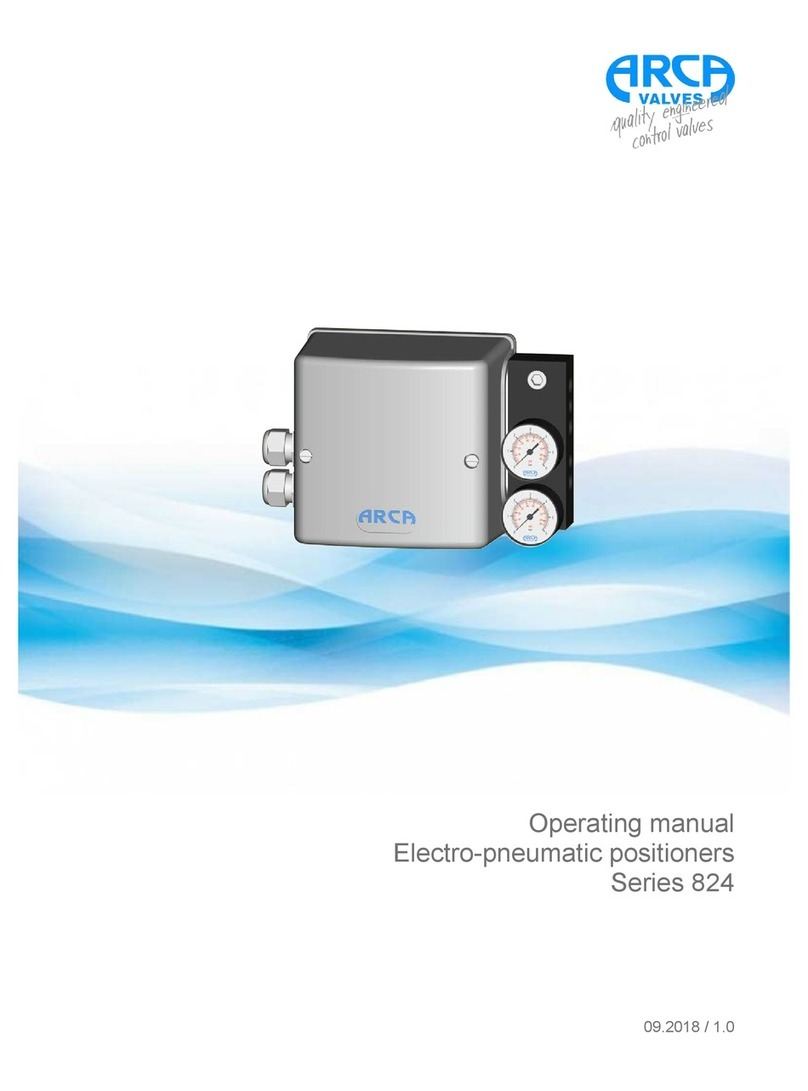
ARCA
ARCA 824 series operating manual
