Bredal F8 User manual
www.bredal.com
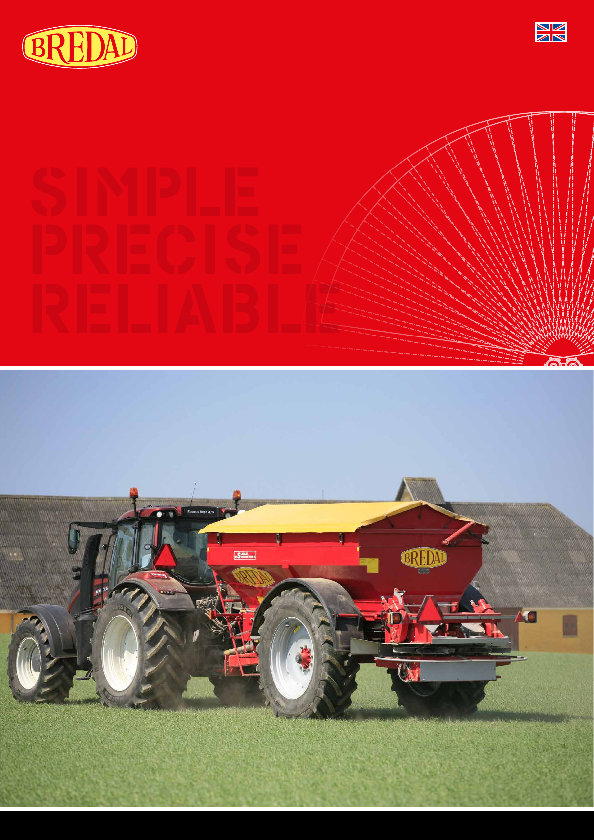
F8/F10
OPERATING INSTRUCTIONS
SIMPLE
PRECISE
RELIABLE
A series of values are entered in the computer of each individual spreader. If a value is mistakenly deleted from the computer, it is possible to re-
enter the original value.
The following values must be entered in the computer in order for all functions to work properly:
(Machinery Directive 2006/42/EF, Annex II, supplement A)
Manufacturer: BREDAL A/S
Nimvej 1
DK-7120 Vejle Ø
hereby declares that
BREDAL Type F8/F10 serial number
is manufactured in conformity with the Machinery Directive (Directive 2006/42/EC), as amended, and with national provisions.
Bredal DK-7120 Vejle Ø August 2016
>EU Declaration of Conformity
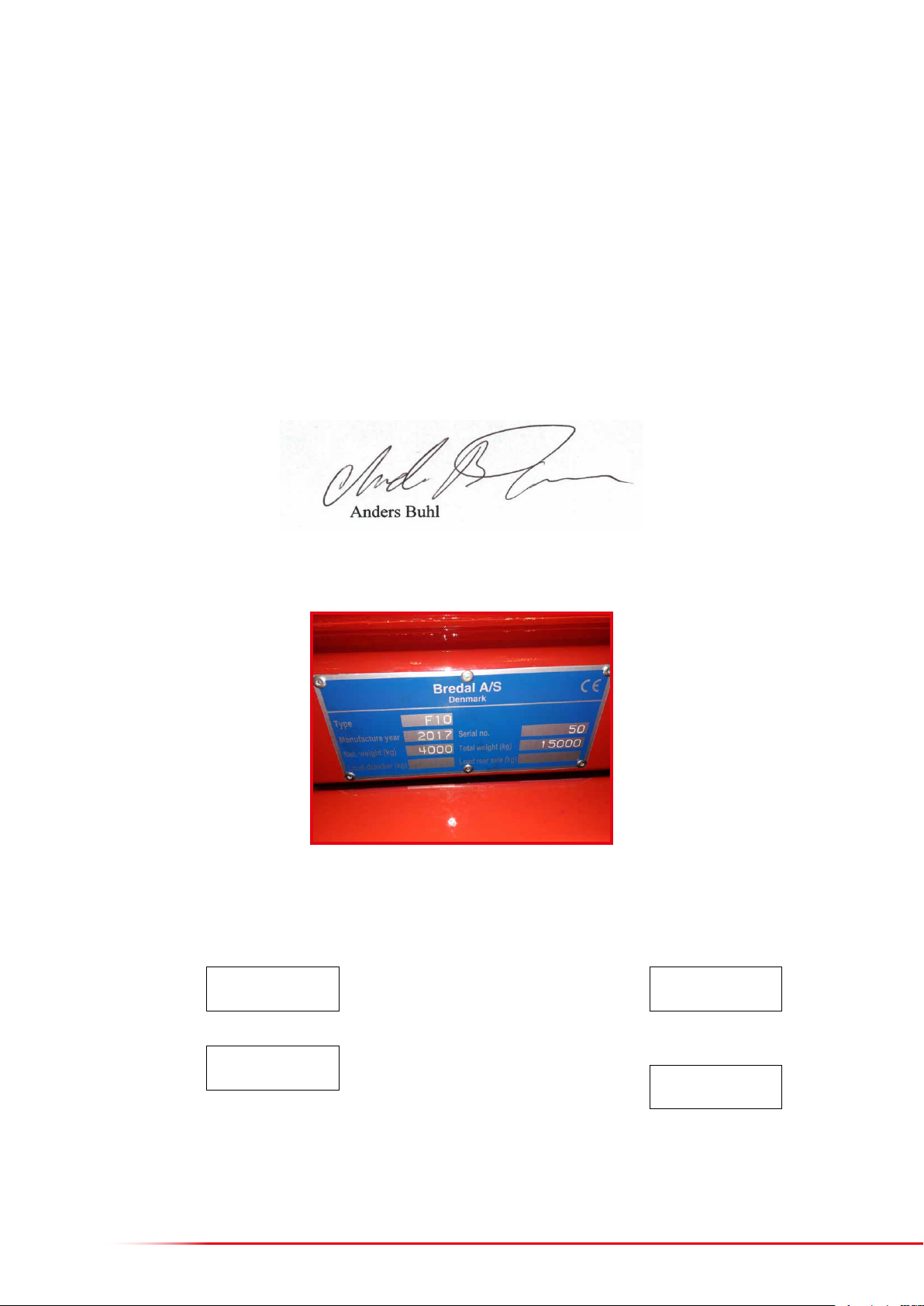
The spreader’s rating plate species the model designation, year of manufacture, net weight, serial number and total weight.
>The spreader’s master data
Errors and omissions excepted.
The terms and conditions of sale and delivery can be found on www.bredal.com/en/betingelser
Weighing:
Calibration gures
Zero load value
Application rate:
Volume per impulse
Speed sensor:
Pulses/100 metres

3
CONTENTS
Foreword 5
Safety 6
Tracsafety 6
Connecting the spreader 7
Initial installation/set-up of a Müller terminal 8
Language, contrast, brightness and units of measurement 9
Initial set-up of an existing terminal in the tractor 10
Switching a screen display to another terminal 11
Description of the Bredal program icons 12
Congurable alarms 14
Menu for entering application rate, working width, density, etc. 16
Enteringtheapplicationrate 16
Enteringtheworkingwidth 17
Enteringthescaleposition 17
Enteringthedownshuteposition 18
Enteringthedensity 19
Enteringtheowfactor 20
Operation screen 22
Operation screen (hydraulic spreading discs) 24
Enteringthedesiredspeedsforeldandheadlandspreading 24
User set-up of operation screen 25
Fast emptying 26
Weighing menu 27
Counters 28
Setting up implement parameters 30
Calibrations 32
Volumeperimpulse 32
Hydrauliccalibration 33
Implementspeedsensor 34
Zeroingtheweightcells 35
Calibratingtheweightcells 36
Newcalibration 37
TC-implementosets 38
Testing input and output 40
Testinginput 40
Testingoutput 41
Reload factory settings 42
Fertiliser quality 44
Eectoffertiliserqualityonspreadingproperties 44
Maximum capacity per minute 45
Settings for various types of fertiliser 46
Fertiliser spreading test and spreading adjustment 47
Ifexcessfertiliserisdepositedbetweenthewheeltracks 48
Ifexcessfertiliserisdepositedbehindthespreader 48
Fertiliserspreadingtest:headlandspreading 48
Engaging/disengaging in headland, manually 49
Calibration kit 50
Late application with late application equipment 51
Troubleshooting and Maintenance
Troubleshooting 52
Rateotarget 52
Floorbeltswhichstoprunningcouldbecausedbythefollowing 52
Right(le)actuatorblocked 53
Checkofgearboxsensor 53

4
Basic settings, adjustment of downshute position 54
Checkingdownshutes’centring 54
Checking/adjustingthedownshutescale 57
Floor belt adjustment 58
Nylonscraper 58
Checking the rear doors and their basic settings 59
Lubrication points 60
Every50hours 60
Every100hours 62
Every200hours 64
Maintenance and lubrication of spread unit 66
V-belttightness 66
Headlandgearfunction 66
Lubrication 67
Gear for oor belt operation 68
Other maintenance and cleaning 69
Oillter 69
Spreadingsystem 69
Washingandstorage 69
Tyre-pressure table 70

5
FOREWORD
Bredal F8/F10 is designed to spread chemical fertilisers and similarly structured materials on farmland. The operator is responsible for ensuring
that the machine is solely used for the intended purpose to avoid property damage and personal injury.
The machine is equipped with a rating plate on which the serial number and year of production are specied. The maximum gross weight and net
weight are also specied on the rating plate. The dierence between the two is the maximum permissible load. If other wheels are mounted, the
user is responsible for ensuring that these can bear the load of the spreader’s gross weight.
This instruction manual contains instructions for operating the machine and setting it to spread generally available commercial fertilisers. As fertiliser
quality can uctuate greatly from one year to the next and from consignment to consignment, it is advisable to always perform a spreading test
if there is any doubt whether the type of fertiliser can be spread on the preferred working width with reasonable results. The latest settings for
the most common types of available fertiliser can be downloaded at any time from Bredal’s website. It is advisable to always do a spreading test
using the type of fertiliser to be spread to test the settings recommended by Bredal. The user is solely responsible for ensuring that the machine
is correctly set and that it works correctly to achieve acceptable spreading. Bredal accepts no liability for spreading errors.
The ISOBUS terminal in the tractor and its soware:
The appearance of the user interface varies slightly from one ISOBUS terminal to another. This is because the terminals have dierent resolutions.
Some spreader functions require specic soware to be installed in the terminal. Wedge spreading is only possible if the terminal has a section-
control program and a tracking program. If fertiliser is applied according to eld and crop maps, the terminal must also contain soware that can
process these maps. When the spreader is connected to the tractor, the spreader’s job computer exchanges data with the tractor’s terminal and
only those functions which are supported by the tractor’s terminal will be active. If the terminal does not contain soware for wedge spreading,
the function cannot be used.

6
SAFETY
The safety distance from the spreading discs is at least 30 metres when these are rotating. If people or animals are within this distance,
the tractor’s PTO must be disengaged.
Never operate the headland gear or adjust the spreader while the spreading discs are rotating.
When loading the spreader, keep foreign objects, such as stones, etc., from getting in the machine’s hopper, as they can cause damage and
be very hazardous for the surroundings.
Sitting/standing on the machine while it is operating or during road transport is not permitted.
Before working on the machine, make sure to disengage the tractor’s PTO and depressurise the hydraulic system.
Shields on PTO shas and the implement must be intact and correctly attached.
>Traffic safety
As trac safety is important when driving on public roads, the following must be checked:
• The light system must be connected to the tractor’s light socket, the lamps must be cleaned, and turning signals and brake lights must work
correctly.
• Reective warning triangles must be intact and clean.
• All hitch and wheel bolts must be tightened to the correct torque.
• The tyre pressure must be correct.
• Make sure there are no cracks in tyres, axles or rims.
• The hitch peg must be properly dimensioned and locked so that it cannot be ejected.

7
When connecting the spreader to the tractor, it is important that it stands horizontally or slightly forward to obtain the best possible spreading
results. It is possible to slightly adjust the height by moving the hitch in its bolt holes on the spreader’s undercarriage.
The hydraulic hoses for operating the application process must be connected to a dual-action outlet on the tractor; 50–60 litres/min. are needed.
The hydraulic hoses for operating headland gear are connected to a dual-action outlet.
The hydraulic hoses for operating a hydraulic hopper ring are connected to a dual-action outlet.
The light plug is inserted in the tractor’s light outlet.
The ISOBUS plug is inserted in the tractor’s ISOBUS socket.
Connect the PTO sha to the tractor’s PTO.
CONNECTING THE SPREADER
8
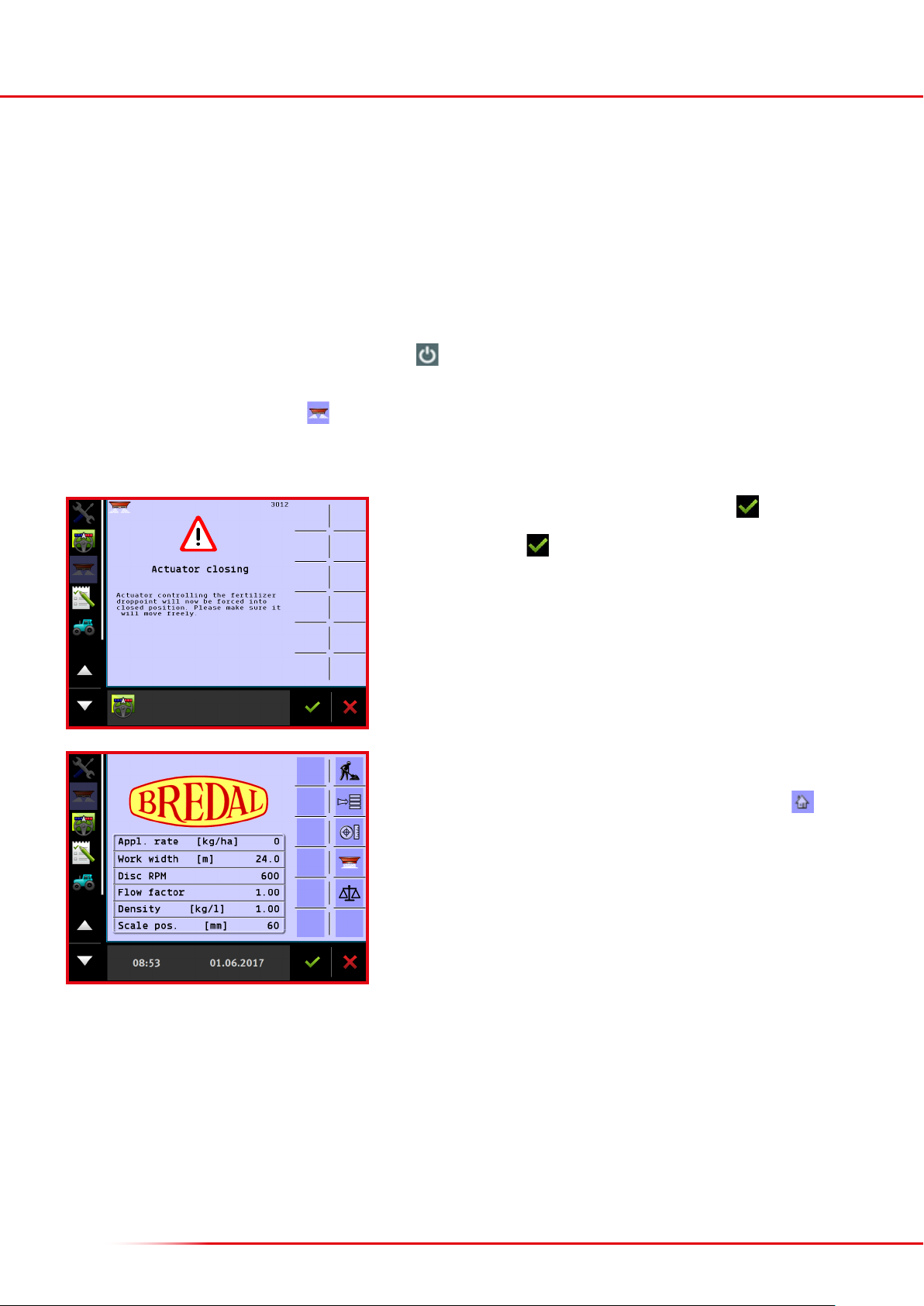
Aer start-up, the warning “Actuator closing” will appear; press to accept.
If “Simulated speed” is activated, an alert about this will also appear, and this must
be accepted by pressing .
If an ISOBUS terminal from Müller is included with the machine, some basic set-up needs to be done before the spreader’s section control can be used.
For installing the tractor mounting set and a GPS aerial, refer to the enclosed instructions from Müller. Also, please refer to Müller’s instructions for
operating programs that do not concern spreader operation, such as Track-leader, Field-nav, Farmpilot, or other soware that can be connected
to the Müller terminal.
The basic GPS receiver set-up, its activation, and the basic encoding of the GPS’s aerial’s location can also be found in Müller’s installation and
operating instructions.
The spreader can be operated once the terminal, tractor-attachment set and GPS aerial have been installed, and the plug from the spreader’s ISOBUS
socket is connected, and basic encoding is completed. Press the button for about 3 seconds. It can take up to two minutes aer switching on
the terminal for the spreader icon to appear on the screen.
If the screen display does not appear, press on the le side of the screen.
INITIAL INSTALLATION/SET-UP OF A MÜLLER TERMINAL
It is now possible to choose from among the various applications on the le side of
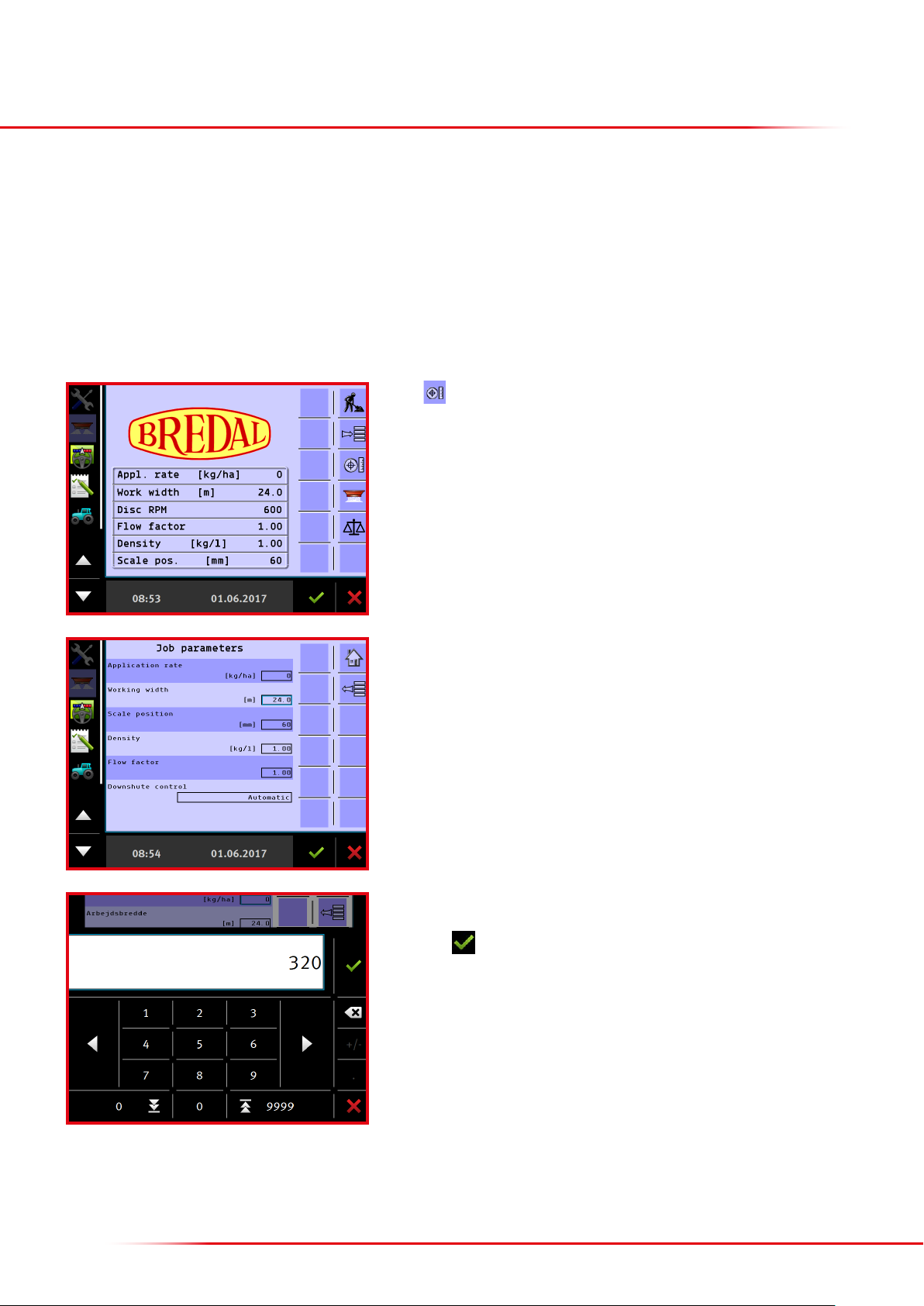
the screen. The spreader’s application is selected on the screen display shown here.
It is always possible to return to this page by pressing the “Home” icon , except
when an input eld is active.
The “Home” start-up screen shows the input application rate, working width, etc.
9
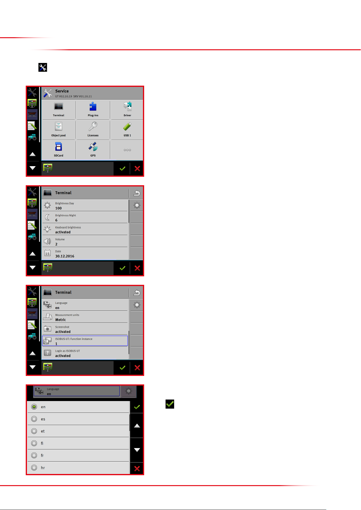
Press to modify the settings:
Select from the list
Press
Press “Terminal”.
LANGUAGE, CONTRAST, BRIGHTNESS AND
UNITS OF MEASUREMENT
Select “Language” by scrolling down.
Click the “Language” tab.
10
INITIAL SET-UP OF EXISTING TERMINAL
IN THE TRACTOR
If the spreader is connected to a tractor with an ISOBUS terminal, it may be necessary to enter the sections’ location and length and indicate that
a tractor mounted spreader is used. The input data is used to ensure that the spreader starts and stops applying fertiliser at the right time when
turning in headland. The Bredal program already contains this information, but not all tractor terminals upload the information from the spreader
when it is connected. Some terminals use the input data correctly. In some instances, the tractor’s terminal uses only one of the two input distances.
Sometimes, the tractor’s terminal does not upload the distances at all; in these cases, the distances must be entered in the tractor terminal’s section
control program. Follow the instructions from the manufacturer of the tractor’s terminal.
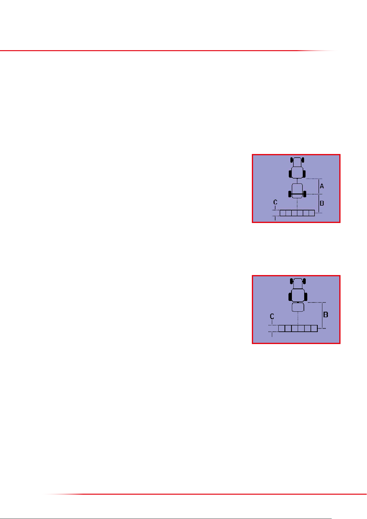
In order for the spreader to start and stop applying fertiliser at the right time, the following distances need to be entered:
• A = distance from the tractor hitch to the spreader axle
• B = distance from the spreader axle to the centre of the swath
• C = length of the swath
If a GPS aerial is mounted on the tractor, the following distances are recommended.
On most terminals, “Tractor drawbar” must also be selected.
• A = 4.0 metres
• B = 8.0 metres
• C = 5.0 metres
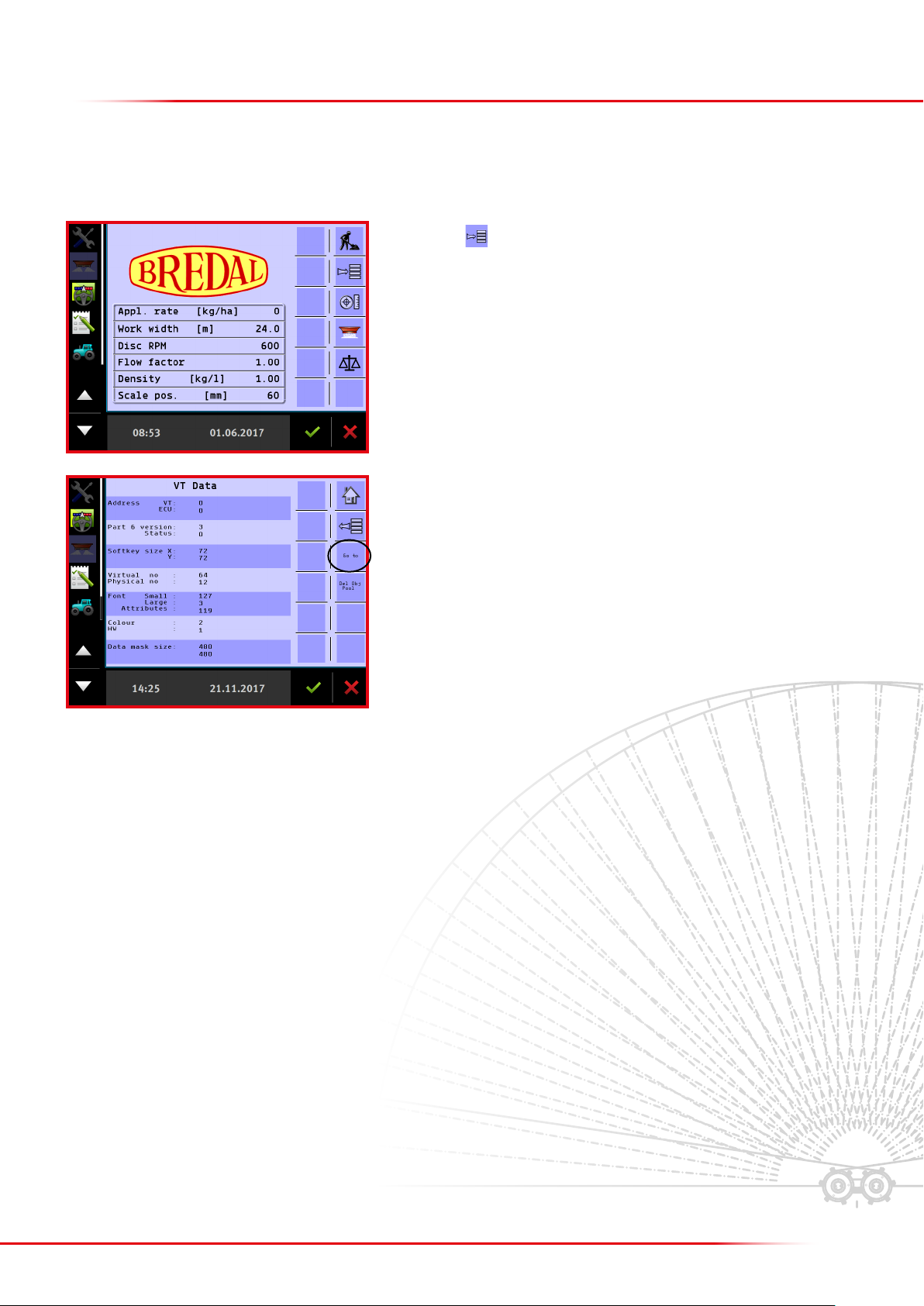
If a GPS aerial is mounted on the front of the tractor, select “three-point hitch” and the following
distances instead.
In this case, B = the distance from the tractor hitch to the middle of the swath.
• B = 12.0 metres
• C = 5.0 metres
11
MOVING A SCREEN DISPLAY TO ANOTHER TERMINAL
If more than one terminal is connected to the tractor’s ISOBUS system, the Bredal program display can be moved from one terminal to the other.
Press “Menu” , then select “Help”, followed by “Diagnostic” and then “VT”.
Press “Go to” on the right side.

12
Home: return to start page.
Work: go to operating page.
Start/stop button: starts and stops the application process.
Menu: go to the menu selected.
Return: go back to the previous menu.
Line down: moves the marking one line down.
Line up: moves the marking one line up.
Emptying: starts the oor belt, emptying the hopper.
Enter application data: goes to the menu where application rate, working width, etc., are entered.
Weighing control: goes to the menu for checking the application rate.
Accept: accepts the input data, or acknowledges an alarm.
Delete: cancels input data.
Toggles between dierent displays.
Manual closing of a section on the right side.
Manual opening of a section on the right side.
The following sections describe the Bredal program icons; their location on the screen can vary from one terminal to another.
Icon meaning/function:
DESCRIPTION OF THE BREDAL PROGRAM ICONS
13
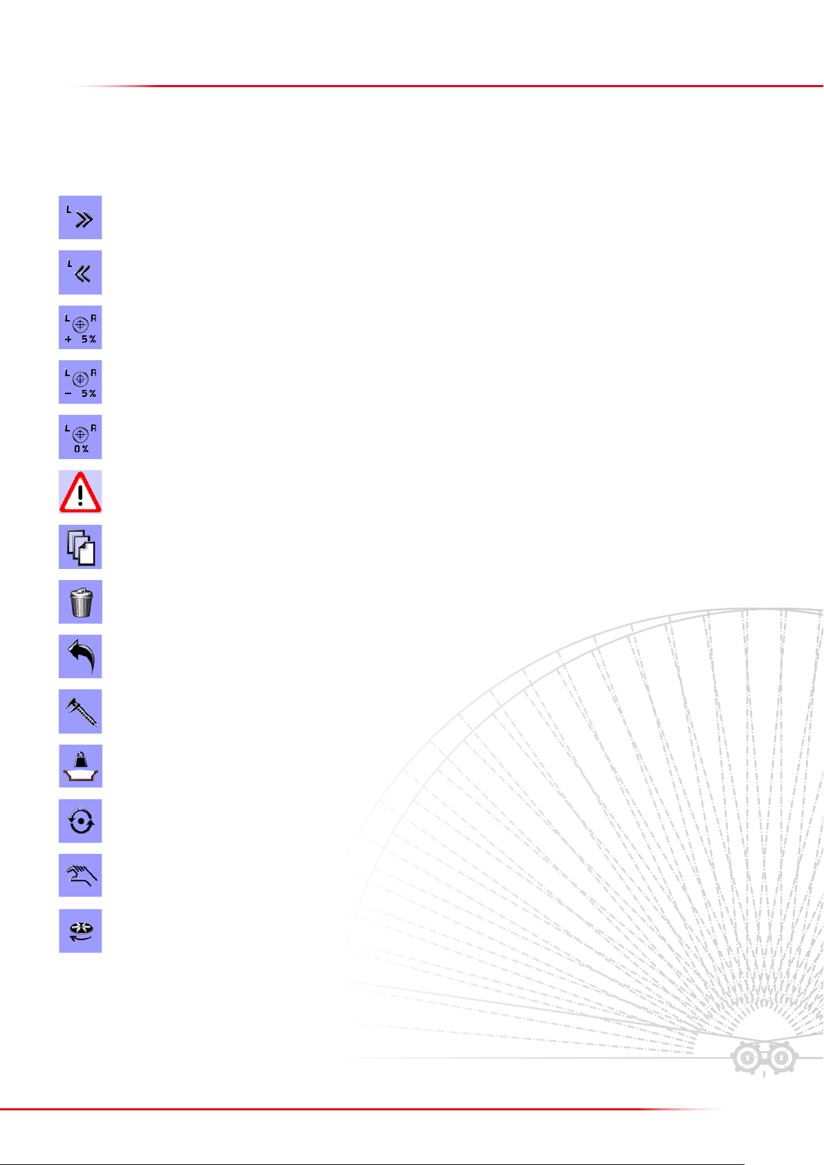
Manual closing of a section on the le side.
Manual opening of a section on the le side.
Increase the spreading volume by 5%.
Reduce the spreading volume by 5%.
Return to the originally entered spreading volume.
Warning/Alarm
Next page: goes to the next page.
Delete: deletes entered data.
ESC: returns without changing a value.
Calibrate:
Start new calculation
Pre-start function
Operate the hydraulic system
Start/stop hydraulic spreading discs

14
Select “Machine”
It is possible to set up individual alarms to issue a warning, such as when the hopper is almost empty. The following alarms are congurable:
• Kg/residual in the hopper
• PTO speed
• CAN speed timeout time
Press the button on the Home screen display.
CONFIGURABLE ALARMS
Select the alarm to be activated
Select “Alarm congurations”
15
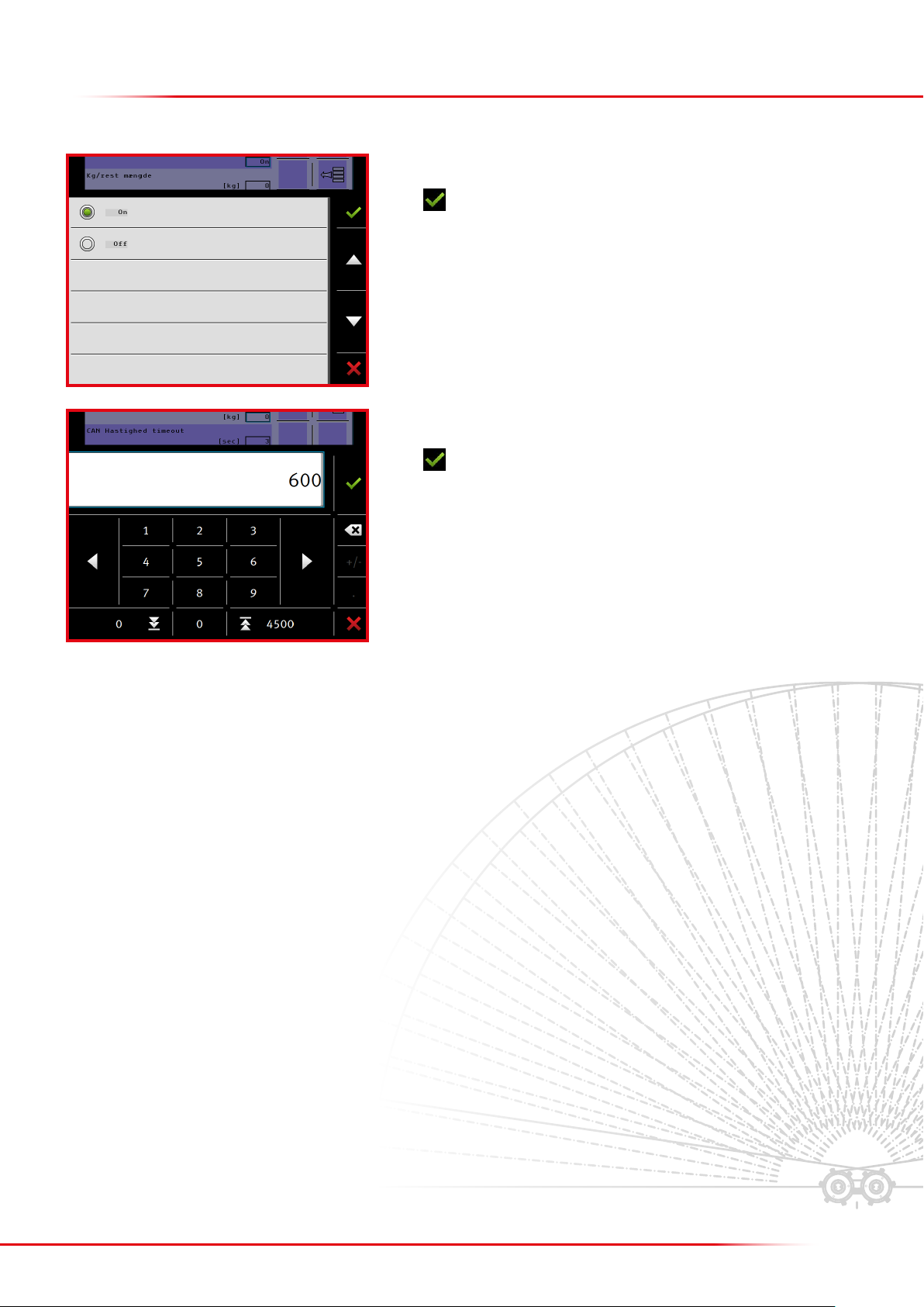
In this example, the alarm is set for kg/residual to be on.
Press to accept.
In the eld below, enter the residual volume (kg/residual) that will trigger the alarm.
Press to accept.
16
MENU FOR ENTERING THE APPLICATION RATE,
WORKING WIDTH, DENSITY, ETC.
The following parameters must be encoded before application begins:
• Kg/ha
• Working width
• Scale position, rear doors
• Downshute position
• Density
• Flow factor
Press to access the task menu.
Enter the preferred application rate.
Finish with
Press the input eld “kg/ha” to change the value.
>Entering the application rate
17
>Entering the working width
Press the input eld “Working width” to change the value.
Enter the preferred working width.
Finish with
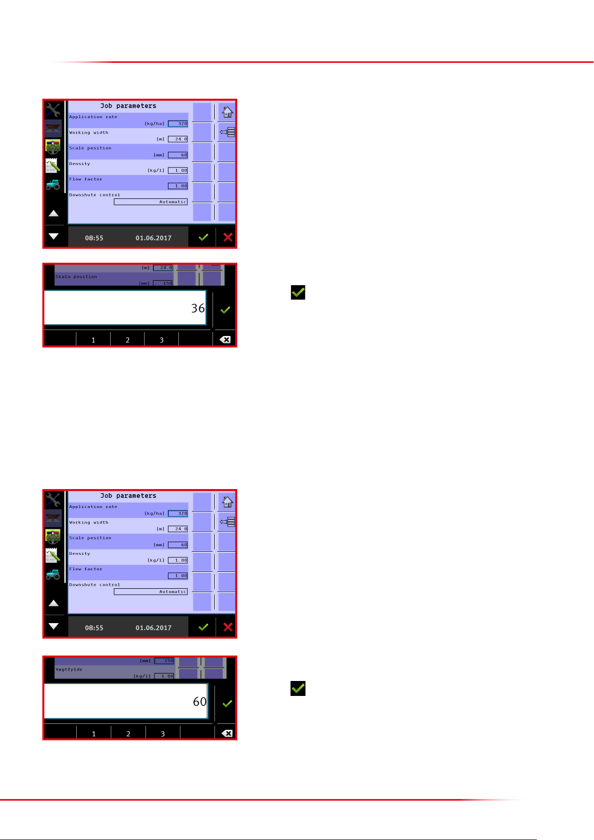
>Entering scale position
The setting for the opening of the rear door is entered under scale position. A scale setting of 60 is advisable. If a very large volume is to be spread,
the setting can be increased to 80 or 100. If a very small volume is to be spread, the setting can be reduced to 40.
NB: it is important to enter the value of the actual rear-door setting, as otherwise the spreader will spread incorrectly.
Press the input eld “Scale position” to change the value.
Enter the position of the rear door.
Finish with
18
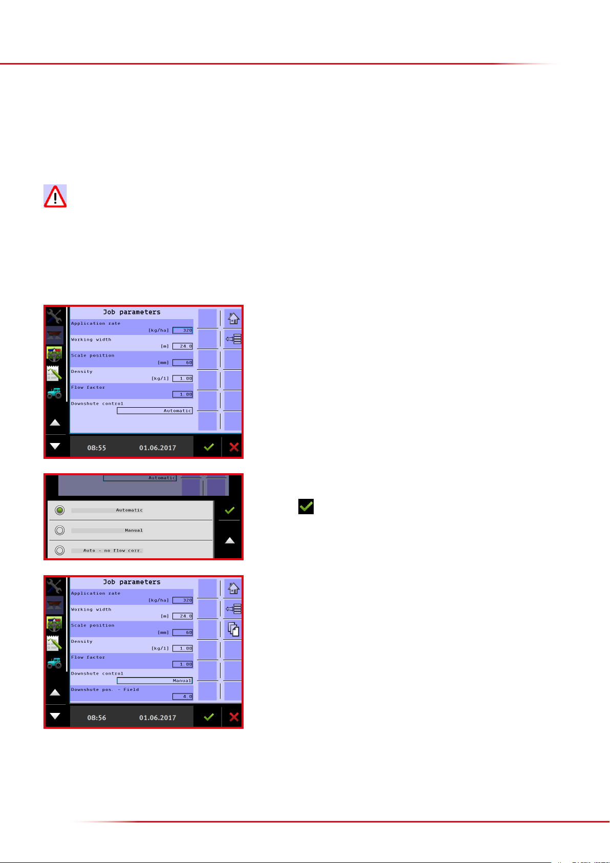
The following dierent setting options are found under downshute control:
• Automatic: the downshutes automatically adjust to the input working width.
• Manual: the preferred downshute position has to be entered.
• Automatic without ow control: the downshute position is not changed by dierent ows
When the working width is changed, downshute control always returns to automatic!
Optimised spreading settings for most fertiliser types can be downloaded from the Bredal website. It is advisable to use manual downshute control
and enter the downshute position that matches the type of fertiliser to be spread.
>Entering the downshute position
Press the input eld “Downshute control” to select.
Select the desired setting.
Finish with
When “Manual” is selected, the downshute position for eld and headland spreading
can be changed.
Press the eld “Downshute pos. eld” to change the setting.
19
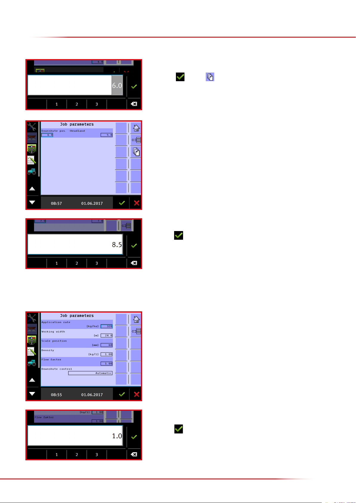
Enter the preferred downshute position for eld spreading.
Finish with or press to go to the next page where it is possible to enter
the downshute position for headland spreading.
Press the eld “Le” or “Right” to change the downshute position for headland spreading.
Enter the preferred downshute position for headland spreading.
Finish with .
Remember to enter the downshute position for both le and right sides, if both sides
have to be changed.
>entering density
Press the input eld “Density” to change the value.
Enter the fertiliser’s bulk density.
Finish with
20
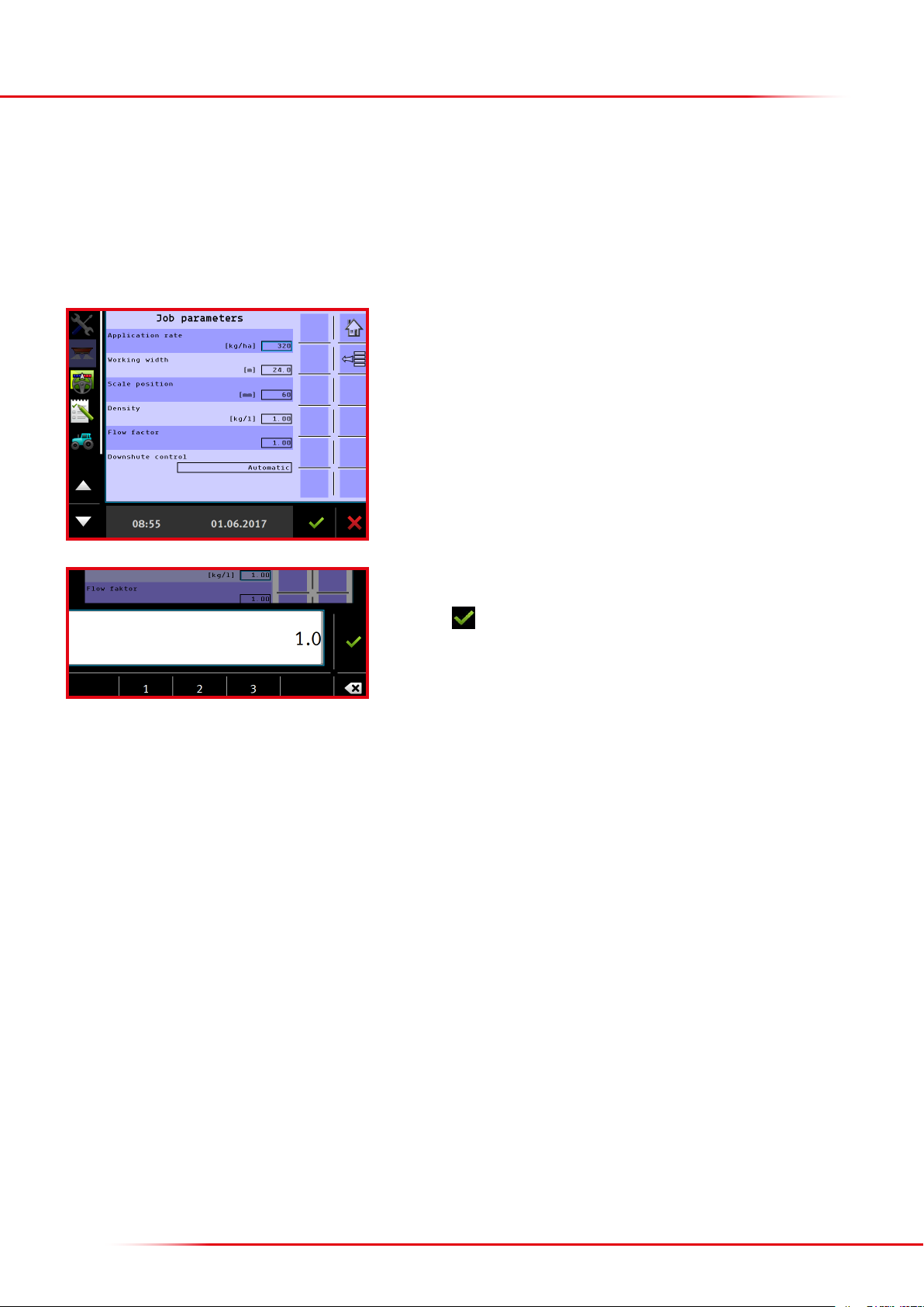
>Entering the flow factor
As a rule of thumb, always start out with a ow factor of 1.0. If the spreader is equipped with weight cells, the ow factor will be continuously
calculated during spreading; the most recently calculated ow factor is shown in the input eld under ow factor.
Press the input eld “Flow factor” to change the value.
Enter the preferred ow factor.
Finish with
Other manuals for F8
1
This manual suits for next models
1
Table of contents
Other Bredal Farm Equipment manuals


Popular Farm Equipment manuals by other brands

Schaffert
Schaffert Rebounder Mounting instructions

Stocks AG
Stocks AG Fan Jet Pro Plus 65 Original Operating Manual and parts list

Cumberland
Cumberland Integra Feed-Link Installation and operation manual

BROWN
BROWN BDHP-1250 Owner's/operator's manual

Molon
Molon BCS operating instructions

Vaderstad
Vaderstad Rapid Series instructions


