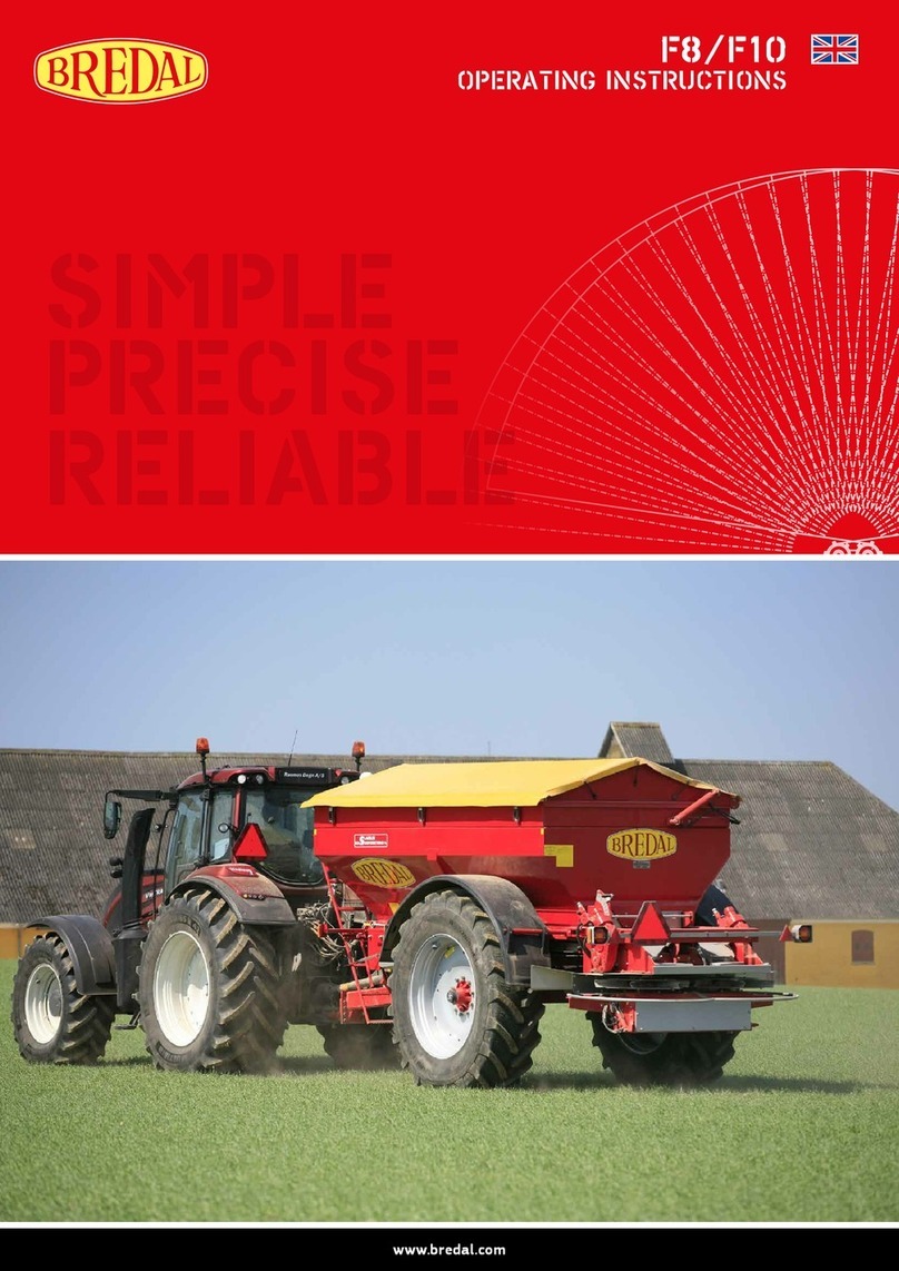
Bredal F8 User manual

www.bredal.com
F8/F10
OPERATING MANUAL
SIMPLE
PRECISE
RELIABLE

Misprints/typos might appear.
General sales and delivery terms and conditions can be found at www.bredal.com/en/betingelser
(Directive 2006/42/EF, Annex II, supplement. A)
Manufacturer: BREDAL A/S
Nimvej 1,
DK-7120 Vejle Ø
Hereby declares that:
BREDAL Type F8 / F10 serial number:
is produced in conformity with Machine Directive (Directive 2006/42/EF)
with changes and with national provisions.
Bredal DK-7120 Vejle Ø August – 2016
>EU Declaration of conformity
Type description, manufacture year, net.weight, serial number and total weight are given on the nameplate.
A number of values is encoded in the computer for each spreader, in case one of the values is deleted from the computer by mistake, the original
value can be encoded again.
The following values shall be encoded into the computer to make sure that all functions operate correctly:
Weighing: Calibrationgure...................
Zero load value. . . . . . . . . . . . . . . . . . . . .
Application rate: Volume per impulse . . . . . . . . . . . . . . . .
Speed sensor: Impulses / 100 meter. . . . . . . . . . . . . . .
>Basic data for a spreader

3
CONTENTS
Introduction 5
Security regulations 6
Tracsecurity 6
Connecting the spreader 7
First time installation / set-up of Müller terminal 8
First time set-up on existing terminal in the tractor 9
Description of Bredal program icons 10
Start-up of the terminal 12
Language, contrast, light and measuring units 13
Calibration of spreader’s speed sensor 14
Congurable alarms 16
Encoding menu for application rate, working width, density etc. 18
Encodingapplicationrate 18
Encodingworkingwidth 19
Encodingscalepositioning 19
Encodingdownchutepositioning 20
Encodingdensity 21
Encodingowfactor 22
Operating picture 24
User setup of operating picture 26
Express unloading 28
Weight menu 29
Counters 30
Setting up machine parametres 32
Machine calibration 34
Hydraulicsystem 35
Encodingspeedsensor 36
Taringofweighingcells 37
Calibrationofweighingcells 38
Newcalibration 39
TC-implementosets 40
Test of inputs and outputs 42
Testinput 42
Testoutput 43
Go back to factory settings 44
Fertilizer quality 46
Impact of fertilizer quality on spreading characteristics 46
Settings for dierent types of fertilizer 48
Spreading tests and adjusting application rate 49
Incasethereistoomuchfertilizerinbetweenthetracks 50
Incasethereistoomuchfertilizerbehindthespreader 50
Spreadingtest:Headlandspreading 50
Connecting/Disconnecting at headland (Manual) 51
Density 52
Late application with the help of specic late application equipment 53
Troubleshooting and maintenance 54
Troubleshooting 54
Errorinapplicationrate 54
Right(le)actuatorblocked 54
Ifbeltsdonotrun,thefollowingmightbethecause: 55
Controlofsensoronthegearbox 55
Basic settings and adjustment of downchute positions 56
Checkingdownchutecentering 56
Control/Adjustimentofdownchutescale 59

4
Adjustment of belt 60
Nylonscraper 60
Checking and basic settings for the rear door 61
Lubrication points 62
Every50hours 62
Every100hours 64
Every200hours 66
Maintenance and lubrication of spreading unit 68
Tightnessofthebelts 68
Headlanddevicefunction 68
Lubrication 69
Gear for operating the belts 70
Tire Pressure Table 72

5
INTRODUCTION
BredalF8/F10isdesignedtospreadarticialfertilizerormaterialssimilartoitonagriculturalareas.Theoperatoraloneisresponsiblefor
the use of the machine exclusively for its intended purpose in order to avoid all kind of damage to own or others’ health as well as property.
The machine is equipped with a name plate, where serial number and factory production year are indicated. Gross weight and tare weight are
indicatedthereaswell.Thedierencerepresentsthemaximallypermissibleload.Incaseifsomeotherwheelsaremounted,itistheuser´s
responsibilitytomakesurethattheycanwithstandtheloadfromthemachine´sgrossweight.
Thisoperatingmanualcontainsinstructionsandguidanceforoperatingthemachineandsettingitforspreadingofcommontypesoffertilizer.
Sincethefertilizerqualitycanvariatequitealotfromyeartoyearandfrombatchtobatch,itisrecommendedthatthereshallalwaysbeper-
formedaspreadingtest,ifthereisaslightestdoubtaboutcharacteristicsofthegivenfertilizertypeinrelationtoitsabilitytospreadonthe
requiredworkingwidthperformingagoodresult.ThenewestsettingsformostcommontypesoffertilizercanbedownloadedfromBredals
homepage.Itisrecommendedthattherealwaysshallbeundertakenaspreadingtestwiththetypeoffertilizerthathastobespread.The
spreadingtestshallbeperformedwiththattypeoffertilizerthatshallbespreadinordertotryouttherequiredsettingsbyBredal.Itisthe
operator´sresponsibilitytomakesurethatthemachineissetcorrectlyandworkslikeitshould,sothatacceptablespreadingpatterncouldbe
achieved. Bredal takes no responsibility for spreading errors.
Isobusterminalinthetractoranditssoware:
TheusersurfacelooksdierenteverytimethemachinegetsconnectedtoanotherISOBUSterminal.Thereasonforthisisthatterminalshave
dierentsolutions.Somefunctionsofthespreaderdependonthetypeofsowaretheterminalhas.Thefunctionsaredependantonthatthe
terminalshallcontainthenecessarysoware.Inordertoperformheadlandspreadingitisnecessarytomakesurethattheterminalcontains
sectioncontrolprogramalongwithtrackfollowingprogram.Iftheapplicationratingshallbebasedontheeldmap,theterminalmustalso
includethesowarewhichisabletooperateeldmaps.Whenthespreadergetsconnectedtothetractor,thespreader’sjobcomputerstarts
to exchange data with the tractor’s terminal, and only the functions supported by the tractor’s terminal would be active. In case the terminal
doesn’tcontainthesowarenecessaryforspreadinginwedges,thefunctioncannotbeapplied.

6
SECURITY REGULATIONS
The secure distance from the spreader’s discs is minimum 30 meters when they are in operation. In case there are people or animals within
thisdistance,thetractor’sPTOshallbeatoncedisconnected.
Never try to service headland device or make setting adjustments on the spreader when the discs are in operation.
Underloadingavoidthesituationwhenforeignobjectslikestoneorsimilarcomeincontactwiththemachine’shopper,astheymightcause
damageandinictgreatdangerforthesurroundings.
The presence in the spreader is forbidden during operation and road transportation.
Beforestartingthespreaderitisnecessarytomakesurethatthetractor’sPTOisdisconnectedandthehydraulicsystemisnotunderpressure.
ScreeningonPTOaxlesandonthemachineshallbeundamagedandcorrectlymounted.
>Traffic security
Whenmovingonthepublicroaditisimportantthattracsecurityisinorder,thefollowingthereforeshallbecontrolled:
• The light equipment shall be connected to the tractor’s light output, the lamps shall be cleaned, lights, turn signals and brake lights must
function correctly.
• Warning triangles shall be intact and cleaned.
• All bolts by drawbar and wheel shall be tightened properly and by correct torque.
• Tyre pressure must be correct.
• There may not be any cracks in the tires, axles and wheels.
• Theplugonthedrawbarshallbeofsubstantialsize,anditshallbelockedsoitcannotjumpup.

7
Whenthespreaderisconnectedtothetractor,itisimportantthatitispositionedhorizontally,orslightlyhunched,inordertoreachthebest
possible spreading results. It is possible to adjust a little bit the height by moving the tension in the bolt holes on the spreader frame.
The hydraulic hoses for operating the dosing shall be connected to a double-acting tractor outlet. 50-60 l/min shall be used.
The hydraulic hoses for operating headland spreading shall be connected to a double-acting headland gear.
The hydraulic hoses for operating hydraulic hopper extension is connected to a double-acting outlet.
Lighting plug on the spreader is connected to the tractor’s lighting outlet.
ISOBUSplugisjoinedtothetractor´sISOBUSconnection.
Universaldriveshaisconnectedtothetractor’sPTO.
CONNECTING THE SPREADER

8
Aerstart-upthereappearsawarning”Actuatorcloses”,click to accept.
If simulated speed is activated, the warning will appear, which is accepted by clicking
.
IncaseanISOBUSterminalfromMüllerisdeliveredtogetherwiththemachine,somebasicset-upshallbedonebeforeapplyingthefunction
of section control.
FormontagingthetractorassemblykitwithGPSantenna,yougetdirectedovertoinstructionsprovidedbyMüller,whereitispossibletoreferto
Müllerinstructionsforoperatingtheprogramsnotrelatingtospreader’soperation,suchasTrack-leader,Field-nav,Farmpilot,orothersoware
thatcanbeboughtadditionallyforMüllerterminal.
The basic set-up of GPS receiver, its activation and the basic encoding for GPS antenna location can be equally found in montage and operating
instructionsfromMüller.
Whentheterminal,tractorassemblykitandGPSantennaaremounted,thesocketfromthespreader’sISOBUSisconnected,thebasicset-up
encodingisnishedandthespreadercanbesetintoaction,pressthebutton for about 3 seconds. It can take up to 2 minutes from the
moment the terminal is switched on until the spreader icon appeares on the screen.
FIRST TIME INSTALLATION /
SET-UP OF MÜLLER TERMINAL
Nowitispossibletochoosebetweendierentparametresonthelesideofthe
screen,e.g.onthegivenscreenpicturethespreader´sapplicationrateischosen.
You can at any moment go back to this page by clicking home icon , except when
theentryeldisactive.

9
IncasethespreaderisconnectedtothetractorthathasISOBUSterminal,itcouldbenecessarytoencodethesections´locationandlength,
during the movement with a trailed spreader. The encodings shall be used for the spreader to start and stop the dosing at the right time, when
turning at headland. Bredal program already contains this information, but not every tractor terminal uploads this data from the spreader when
connected.Someterminalsapplytheencodingscorrectly.Insomecasesthetractor´sterminalappliesonlyoneortwooftheencodeddistances.
Sometimestheterminalcannotatallrecognizethedistances,insuchcasestheyshallbeencodedintosectioncontrolprogramofthetractor
terminal, follow the instructions of the manufacturer of the terminal.
To ensure that the dosing starts and stops at right moments, the following distances shall be encoded:
• A=Thedistancefromthetractor´spulltothespreader´saxle.
• B = The distance from the spreader’s axle to the middle of the spreading pattern.
• C = The length of the spreading pattern.
DistanceguresrecommendedbyBredal:
• A = 4,0 meter
• B = 6,0 meter
• C = 5,0 meter
Onmostterminalsitisnecessarytofurtherchooseatractordrawbar.
FIRST TIME SET-UP ONTO
EXISTING TERMINAL IN THE TRACTOR

10
Home, go back to starting page.
Work, go to operating page.
Start / stop button, starts and stops the dosing.
Menu, go to the chosen menu.
Return, go back to the previous menu.
Go to the line below, the marked line moves one line down.
Go to the line above, the marked line moves one line up.
Emptying, starts the conveyor belt so that the hopper empties.
Encoding application rate, go to the menu where application rate parametres, working width etc. is enlisted.
Weighing control, go to the menu for application rate control.
Accept the entered data or conrm the alarm.
Delete, cancel the entry.
Scroll between dierent views.
Manual closing of the section on the right side.
Manual opening of the section on the right side.
InthefollowingpassageyoucanndadescriptionofBredalprogramicons,thepositioningoficonscanvariateondierentterminals.The
icon´smeaning/function:
DESCRIPTION OF BREDAL PROGRAM ICONS

11
Manual closing of the section on the le side.
Manual opening of the section on the le side.
Increase output amount by 5%.
Reduce output amount by 5%.
Return to the original encoded output amount.
Warning / Alarm
Go to the next page.
Delete the entry.
ESC, go back without changes.
Calibrate.

12
Click to accept.
Presson/obuttonontheterminal.Whentheterminalstarts,thespreader´sprogramisloadedautomatically,thepopping-upwarning”Actuator
closing”shallbeconrmedfor.
START-UP OF THE TERMINAL
Then the start-up screen picture (Home) is shown. Here you can see the entered
application rate, working width etc.
In case the start-up screenshot can not be seen, click onthelesideofthe
screen.

13
Click to change the settings:
Choose from the list
Click
Click“Terminal”.
LANGUAGE, CONTRAST, LIGHT AND MEASURING UNITS
Selecte.g.“Language”byscrollingdown.
Clickatthetabpage“Language”.

14
Select“Machine”
Pay some attention to that it is possible to choose other speed sources than the spreader’s speed sensor, e.g. the speed via GPS signal, see VT
instruction manual for the terminal.
Click menu button at Home screen picture.
CALIBRATION OF SPREADER’S SPEED SENSOR
Select“Implementspeedsensor”
Select“Calibrations”

15
Click to start calibration.
The number of impulses can be directly introduced into the entry line in settings, if
the amount is known.
Move 100 meter forward, the impulses are calculated.
Click to save the calculated amount of impulses.

16
Select“Machine”
It is possible to set some individual alarms, so that there comes a warning e.g when the hopper is almost empty. The following alarms can be
congurated:
• Kg/leinthehopper
• PTOspeed
• CAN speed timeout point
Click button at Home screen picture.
CONFIGURABLE ALARMS
Select the alarm that shall be activated
Select“Alarmcongurations”

17
Inthisexamplealarmissetforkg/leat”On”.
Click to accept.
Theentryeldbelowismeantforintroducingtheresidualquantitykg/leatwhich
thealarmshallgoo.
Click to accept.

18
ENCODING MENU FOR APPLICATION RATE,
WORKING WIDTH, DENSITY ETC.
The parametres that shall be encoded before the start of spreading are the following:
• Kg/ha.
• Working width
• Rear door scale position
• Downchute position
• Density
• Flow factor
Click to go to the task menu.
Encode the required application rate.
Complete by clicking
Click“kg/ha”intheentrylinetochangethevalue.
>Encoding application rate

19
>Encoding working width
Clicktheentryspace“Workingwidth”tochangethevalue.
Encode the required working width.
Complete by clicking
>Encoding scale position
UnderthelineScalePositionthesettingsforthereardooropeningshallbeencoded.Itisrecommendedtodrivewithascalesettingon60.If
bigger amounts of material are dosed, the scale settings are increased up to 80 or 100. If small amounts are to be dosed, the settings are
reduced to 40.
NOTE,itisimportanttoencodethatvaluethatthereardoorissetfor,orelsethespreaderwilldoseincorrectly.
Clicktheentryspaceby“Scaleposition”tochangethevalue.
Encode the rear door position.
Complete by clicking

20
Underthefandownchutecontroltherearemanydierentsettingoptions,thatcanbechosenamongthefollowing:
• Automatic, downchutes adjust automatically to the encoded working width.
• Manual, the required downchute position shall be encoded.
• Automaticwithoutowcontrol,similartoautomatic,withtheonlydierencethatthepositionofdownchutesisn’tchangedatdierentow
patterns.
When the working width is changed, downchute control always goes back to automatic!
OptimizedsettingsforthemostfertilizertypescanbedownloadedatBredalhomepage,itisrecommendedtoapplymanualcontrolofdown-
chutesposition,andencodethatpositionofdownchutethattsforthefertilizertypetobespread.
>Encoding downchute position
Clicktheentryspaceby“Downchutecontrol”forselecting.
Select the required setting.
Complete by clicking
When introduction of manual settings is completed, settings for downchute positioning
forin-eldandheadlandspreadingcanbeadjusted.
Other manuals for F8
1
This manual suits for next models
1
Table of contents
Other Bredal Farm Equipment manuals
Popular Farm Equipment manuals by other brands

Schaffert
Schaffert Rebounder Mounting instructions

Stocks AG
Stocks AG Fan Jet Pro Plus 65 Original Operating Manual and parts list

Cumberland
Cumberland Integra Feed-Link Installation and operation manual

BROWN
BROWN BDHP-1250 Owner's/operator's manual

Molon
Molon BCS operating instructions

Vaderstad
Vaderstad Rapid Series instructions


