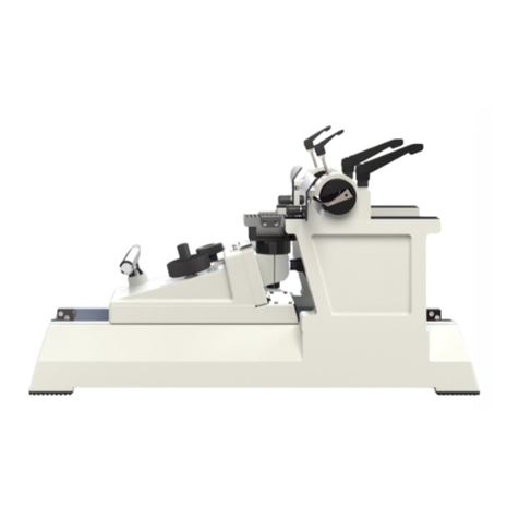
Bright Instruments 2212 Starlet User manual

Instruments
Instruments
Instruments
Instruments
Instruments
Instruments
2212 Starlet
Bench-Top
Portable
Cryostat
Manual

Bright Instruments 2
Contents
SAFETY WARNINGS 4
Low temperature 4
Knives / blades 5
SAFETY INFORMATION 6
Consumer protection 6
Electrical 6
Mechanical 6
Operation 7
Accessories 7
UV light power unit (when supplied) 7
Decontamination procedures 7
WARRANTY 9
1 INTRODUCTION 10
1.1 Receipt of Product 10
1.1.1 Receipt and unpacking 10
1.1.2 Receipt 10
1.1.3 Unpacking 10
1.2 Assembly & Installation 10
1.2.1 Fitting hand wheel 10
1.2.2 Installation of accessories 10
1.2.3 Insulating plug 11
1.2.4 Positioning 11
1.3 Electrical Connections 11
1.3.1 Settling 11
1.3.2 Electrical requirements 11
1.3.4 Switching on 11
2 OPERATING INSTRUCTIONS 12
2.1 Control Panels 12
2.1.1 Mains switch 12
2.1.2 Defrost clock 12
2.1.3 Chamber temperature 12
2.1.4 Defrost switch 12
2.1.5 Quick freezer temperature 12
2.2 Microtome Controls 13
2.2.1 Blade guard 13
2.2.2 Blade holder 13
2.2.3 Blade angle 13
2.2.4 Coarse advance control 12
2.2.5 Section thickness control 14
2.2.6 Object holder 14

Bright Instruments 3
Contents Cont.
3 ANTI-ROLL ASSEMBLY 15
3.1 Parallel adjustment 15
3.2 Height adjustment 15
3.3 Magnaplate anti-roll plate 15
4 CUTTING & COLLECTING 16
SECTIONS
4.1 Trimming 16
4.2 Section cutting 16
5 GENERAL MAINTENANCE 17
5.1 Daily Care 17
5.2 Automatic Deforst Cycle 17
5.3 Total Defrosting 18
5.4 Operating in Extreme Conditions 18
5.5 Service & Repairs 19
5.6 Decontamination 20
5.6.1 Formaldehyde decontamination 20
5.6.2 Virkon decontamination 20
6 FROZEN SECTIONING: 22
PROBLEM SOLVING GUIDE
6.1 Checklist 22
6.1.1 Specimen 22
6.1.2 Blade check 22
6.1.3 Anti-roll plate 22
6.2 Intermittent failure to cut 22
6.3 Sections crumbling/not forming 22
6.4 Excessive compressions 22
of sections
6.5 Uneven thickness across section 23
6.6 Vertical score marks on section 23
6.7 Sections Curling 23
6.7.1 Sections curl over anti-roll plate 23
6.7.2 Sections curl under anti-roll plate 23
6.7.3 Sections curl under 23
and stick to anti-roll plate
6.7.4 Sections curl after lifting 23
anti-roll plate
6.8 Sections fail to flatten 23
and pass down blade
6.9 Cutting Temperatures 23
6.9.1 Fresh, unfixed tissue 23
6.9.2 Fixed tissue 23
7 SPECIFICATIONS 24
ACCESSORIES & CONSUMABLES 25
MATERIAL SAFETY DATA SHEETS 26
Cryo-M-Bed 53581 27
Cryospray 57713 28
Low Temperature Oil 57491 34
REFERENCES & DRAWINGS 36
Figure A. Quick Freezer Bar 37
Figure 1. Blade Holder 38
Figure 2. Blade Angle 39
Figure 3. Blade Angle Adjustment 39
Figure 4. Coarse Advance Control 40
Figure 5. Section Thickness Control 40
Figure 10. Trimming 41
Figure 11. Trimming 41
Figure 15. Pawl Assembly 42
Figure 16. Pawl Adjustment 42
Rotary Handwheel Diagram 43
DWG: 136026-01 44

Bright Instruments 4
SAFETY WARNING
Low temperatures are present in this
equipment. Extreme care should be taken.
DO NOT let bare skin come into contact
with metal surfaces.

Bright Instruments 5
SAFETY WARNING
Extremely sharp knives/blades.
Use knife/blade guards at all times.
Use correct tools for removal and insertion of knives/blades.
DO NOT leave knives/blades laying around.
Place knives/blades not in use, into box/wallet provided.

Bright Instruments 6
Safety Information
CONSUMER PROTECTION
The Consumer Protection Act 1987 Part 1,
refers to Product Liability. This legislation was
issued as a direct result of an EC Directive to
all member states and has been in force with
effect from 01 March 1988.
Bright Instrument Company Limited, ever
mindful of the need to ensure that their
products are not subject to misuse and/or
incorrect handling, have made it their aim to
communicate any possible dangers to their
customers.
Whilst Bright Instrument Company Limited
markets products manufactured to the highest
safety standards, it is in the interest of the
purchaser that he is aware of the resultant
dangers of misuse and/or incorrect handling
of these products.
Your attention is therefore drawn to the
following precautions:
ELECTRICAL
a. Warnings - A warning notice is fixed to
the instrument stating that it should be
disconnected from the power supply before
removing the panels. This warning should
be strictly observed. This cryostat is fitted
with an in line mains filter which may affect
portable appliance test results.
b. Fuses - Fuse ratings are clearly indicated
on all fuse panels adjacent to the fuse holder.
If and when replacement is necessary, the
correct fuse rating must be adhered to.
c. Earthing (Grounding) - A protective earth
terminal is fitted, and must be used in all two
wire installations.
MECHANICAL
Microtome knives can be hazardous in the
laboratory. Personnel should be made aware
of the dangers and observe the following
warnings:
a. Do not leave the microtome unattended
with an exposed knife in position. Remove the
knife, or cover it with the guards provided.
b. Do not leave knives lying around. Place
knives that are not in use in their boxes.
c. Do not carry knives unless secure in the
box provided.
d. Do not clean the knife along its length.
Wipe from the back edge of the cutting edge.
e. Remember that even used knives are
dangerous – they are still sharp and may
have been used to cut potentially infectious
specimens.
f. Dispose of used knives with the same care
as other sharp objects. On no account should
used knives be placed in waste bins.

Bright Instruments 7
Care must be taken when using Cryospray
134. The risk of creating an aerosol of
potentially infectious tissue particles must be
borne in mind.
All communications should be direct to our
Quality Assurance Department and will be
acknowledged.
UV LIGHT POWER UNIT (WHEN SUPPLIED)
This switchable power output provides an
electrical supply for the optional UV light unit.
WARNING: The UV lamps emit short
wavelength UV (UVC) radiation, which is
potentially harmful to skin and eyes, and
therefore adequate safety precautions
must be taken.
It is a condition of the supply of this
option that you accept the responsibility
of ensuring that users are aware of
this situation.
OPERATION
When placing object holders in the microtome,
when orientating, manipulating or in any way
placing fingers in a position above the knife
edge – ensure that the hand wheel is locked
and knife guards are in position.
Parts of this instrument may attain
temperatures as low as minus 55ºC. It is
important to avoid allowing bare skin to touch
such cold surfaces – when in doubt, wear
gloves. Avoid touching the knife – it is cold as
well as sharp! ALWAYS use knife guards
ACCESSORIES
Fluids supplied as accessories with Bright
Instruments, such as Cryospray 134,
Cryo-M-Bed and microtome oil, are strictly
for laboratory use only. They should not be
taken by mouth and precautions afforded to
other laboratory chemicals should be adhered
to. Please refer to the material safety data
information.
DECONTAMINATION PROCEDURES
Cryostats & Ultra Low Temperature
Freezing Units: If decontamination is
required carry out the standard procedures
as practised in your laboratory. It is the
responsibility of the customer to use a
decontamination procedure appropriate to
his/her work. The following decontamination
method is as recommended in the ‘Code of
Practise for the Prevention of Infection in
Clinical Laboratories and Post-mortem Rooms’,
ISBN 0 11 320464 7.
a. Bring the cryostat to room temperature.
b. Place 50-100ml of formalin BP in a flat dish
inside the chamber. Close the window.
c. Leave for at least 24 hours, preferably
48 hours.
d. Open the window and place a beaker
containing 10ml of ammonia SG.880 in the
chamber. Close the window.
e. Leave for one hour. The cryostat is
now decontaminated.essential that it
be decontaminated.
Safety Information Cont.

Bright Instruments 8
DECONTAMINATION PROCEDURES CONT.
Microtomes: If decontamination is required
carry out the standard procedures as
practised in your laboratory. It is the
responsibility of the customer to use a
decontamination procedure appropriate to
his/her work.
Microtomes Knives: If decontamination is
required carry out the standard procedures
as practised in your laboratory. It is the
responsibility of the customer to use a
decontamination procedure appropriate to
his/her work.
For further information regarding alternative
decontamination procedures please refer to
‘Safe Working and the Prevention of Infection
in Clinical Laboratories’, ISBN 0 11 885446 1.
Safety Information Cont.

Bright Instruments 9
Warranty
i. The Seller ‘s products are carefully inspected
and submitted to its standard tests.
ii. The Seller warrants all its products to be
free from defects in workmanship and
materials under normal conditions of use and
service provided always:
a. That if any of the goods so manufactured
is alleged to be defective in workmanship
and material and is returned carriage paid,
and protected against damage in transit to
the Seller’s works at Huntingdon within 12
months from the date of despatch and if
after examination by the Seller that goods
or part of them are found to be so defective
then the Seller will repair or replace them free
of charge and will return them to the Buyer,
carriage paid.
b. Where any part of the goods manufactured
by the Seller is repaired or replaced under
the terms of the foregoing warranty, such
warranty shall thereafter be limited to a
period of six months from the date when
the goods shall have been re-delivered
to the Buyer.
c. This warranty does not apply to any defects
caused by wear and tear, incorrect installation
abnormal conditions of working, accident,
misuse or neglect.
d. That save as in this clause herein before
expressed, the Seller shall not be under any
liability for negligence or otherwise in respect
of defects in goods delivered or for any injury,
damage or loss resulting from such defects
and the Seller’s liability under this clause shall
be in lieu of any warranty or condition implied
by law as to the quality or fitness for any
particular purpose of such goods.
e. This warranty is expressly in lieu of all
other warranties, guarantees or liabilities
expressed or implied by any of the Seller’s
Representatives or Agents.
Please see our separate Product Warranty
sheet for deliveries to the mainland UK.
WARNING: Before proceeding to Operating
Instructions, ensure you are familiar with
the contents of the pages marked ‘Safety
Information’. This instrument must only be
used by competent persons.

Bright Instruments 10
1. Introduction
1.1 RECEIPT OF PRODUCT
1.1.1 RECEIPT AND UNPACKING
This instrument received a final test and
inspection prior to despatch from the factory.
The following instructions are given for the
re-assembly of the instrument, adjustments
and its correct use. If the instrument is
received before preparations for installation
are completed. It should be stored in a clean,
dry place and not exposed to dirty or damp
conditions.
1.1.2 RECEIPT
Immediately upon receipt of the instrument,
make a careful examination for evidence of
damage encountered in transit. If any damage
is found or suspected, notify both the carrier
and Bright Instrument Company Limited
immediately.
1.1.3 UNPACKING
All packing must be carefully removed and
parts checked against the enclosed packing
list. If any damage or discrepancy is noted,
please inform our agent/distributor or Bright
Instrument Company Limited immediately.
1.2 ASSEMBLY & INSTALLATION
1.2.1 FITTING HAND WHEEL
(MODELS WITH HAND WHEEL ONLY)
Push the hand wheel over the shaft on the
right side of the cabinet. Ensure pin on shaft
engages slot in centre of hand wheel, press
firmly home then fit centre screw.
1.2.2 INSTALLATION OF THE MICROTOME
(ALWAYS INSTALLED ON INITIAL
DESPATCH)
The microtome is supplied already installed
in the chamber, carefully remove the packing
from around the microtome and the anti-roll
plate and turn the plate so it faces the
blade holder. Note that the metal plate at
the back of the chamber is held in place with
adhesive tape during transit – remove and
discard the tape.
Fit the stainless-steel shelf to the sides of the
chamber on the two studs provided. Place the
black quick freezer bar in position at the front
right side of the chamber and locate with lock
pin as shown below.
Refer to Figure A.
The freezer bar can be used to freeze
specimens to the specimen holders.
If the Starlet is the lever operated version,
screw the lever into position on the right side
of the microtome, using the black knob on.

Bright Instruments 11
1. Introduction Cont.
1.2 ASSEMBLY & INSTALLATION
CONT.
1.2.3 INSULATING PLUG
The insulated plug should be fitted into
position in the top of the chamber at all times,
except when the cryostat is actually in use.
1.2.4 POSITIONING
As free air flow around the cryostat is
essential, take care that the vents at the
sides of the cryostat are not restricted.
1.3 ELECTRICAL CONNECTIONS
1.3.1 SETTING
During transit the oil in the compressor will
have been subject to movement, so it is
important to let the instrument settle before
switching on. We recommend the instrument
is left standing for at least eight hours, and
preferably overnight, before switching on.
1.3.2 ELECTRICAL REQUIREMENTS
The supply cord of the instrument should be
connected to any ordinary electrical outlet
(minimum 13 amps for 220/240v or 20 amps
for 110/115v) a 13 amp or 20 amp fuse should
be incorporated in the line. Check the voltage
stamped on the name plate, located on the
back of the cabinet tallies, with your supply.
The connections are:
Brown - Positive (live)
Blue - Negative (neutral)
Yellow/Green - Earth (ground)
1.3.3 SWITCHING ON
After settling, switch on the mains
(Section 2.1.1) Initially the LEDS displays will
flash for a few seconds. Once the displays are
constant, the required chamber temperature
can be set (Section 2.1.3)

Bright Instruments 12
2. Operating Instructions
2.1 CONTROL PANELS
2.1.1 MAINS SWITCH
This is located on the rear panel. It is
recommended that the cryostat is left running
even if it is not being used regularly.
2.1.2 DEFROST CLOCK
Set the clock on the rear panel to the actual
time by turning the clear plastic disc with
your finger. [See Section 3.2 for additional
information on defrosting.]
2.1.3 CHAMBER TEMPERATURE
This is located on the top control panel.
See Fig B
To set chamber temperature, press and
release Set button, then press Up or Down
buttons until desired temperature is set. After
5 seconds the actual chamber temperature
will show.
To review set temperature at any time press
and release Set button.
WARNING: Do not hold the Set button
down for more than 6 seconds as the
control will go into a diagnostic/calibration
mode.
If the diagnostic/calibration mode is
selected in error, take the following steps:
a. If Up or Down have not been pressed
(ie: no new parameters have been entered),
simply leave for 20 seconds. Display will
revert to normal.
b. If new parameters have been selected
contact Bright Instrument Company Limited
or your local representative for advice.
2.1.4 DEFROST SWITCH
When on, a defrost heater is activated during
the defrost cycle. (Section 3.2).
APP'D
DO NOT SCALE!
DECIMAL:
WHOLE NUMBERS:
ANGULAR:
COPYRIGHT PROTECTED - ALL RIGHTS RESERVED
Starlet
IF IN DOUBT ASK!
3RD ANGLE
PROJECTION
MM
18/09/2019
1:5
SCALE
1 OF 1
SHEET
A2
0,10
0,50
0,5
LJ
1. REMOVE ALL BURRS, SHARP EDGES AND CORNERS.
2. ALL SURFACES TO BE CLEAN AND SCRATCH FREE.
Instruments
Starlet 2212
DEFROST
OFF
SET SET
CHAMBER TEMPERATUREQUICK FREEZER TEMPERATURE
Instruments
Starlet 2212
DEFROST
OFF
SET SET
CHAMBER TEMPERATUREQUICK FREEZER TEMPERATURE
PLEASE NOTE: The defrost switch should
remain on all the time that the cryostat is
switched on. This is because once every
24 hours it is necessary to heat the
evaporator fins to melt the frost on them,
to keep the refrigeration system running
efficiently. During the heating cycle a small
amount of water might be released from
the drain at the rear of the cryostat and
a small container should be used to catch
this water.
2.1.5 QUICK FREEZER TEMPERATURE
Also located on the top control panel, this
constantly displays the temperature of the
quick freezer bar.

Bright Instruments 13
2. Operating Instructions
Cont.
2.2 MICROTOME CONTROLS
This is located on the rear panel. It is
recommended that the cryostat is left running
even if it is not being used regularly.
2.2.1 BLADE GUARD
This should be in position against the blade at
all times when a blade is fitted, except when
sections are being cut.
2.2.2 BLADE HOLDER
Refer to Figure 1.
The blade is held in position by a series of
powerful magnets located on the blade holder.
Before positioning the blade, it is important
to ensure that the holder is completely free
of ice, frost or debris that could prevent the
blade form seating perfectly. A dirty blade
holder will almost certainly cause blade
vibration and bad sectioning.
Frost and ice can be removed from the holder
by scraping it with a wooden or plastic
scraper or wiping it with a cloth dampened
with alcohol.
After cleaning, be sure to remove all traces of
alcohol by wiping it with a dry cloth.
Take a new blade from the dispenser and
remove the grease with solvent.
To position the blade, place it in the slot on
the left side of the blade holder, then slide it
in, keeping it in place on the ledge. When one
of the holes in the blade appears, top sliding
by hand. Locate the small circular tip of the
blade handling device in the hole and slide
the blade into position. To obtain maximum
use of the blade, slide it to a new position
when the edge has dulled. After half the
blade has been used in this way, remove it as
described below, reverse and re-position it.
To remove a used blade, hook the blade
handling device above the dull edge centrally
over the hole. Press the lower round projection
of the device into the hole in the blade.
Then slide the blade up and away from the
magnetic holder.
The blade may now be detached from the
device and safely disposed of. If the blade has
been used only at one end, it may be reversed
and refitted as described above.
2.2.3 BLADE ANGLE
Refer to Figure 2 & 3.
The blade holder is clamped in position
against a cam by means of the knob (39).
To adjust the blade angle, slacken the cam
lock screw (25) and reposition the cam by
moving the knife angle adjuster (24), the angle
is indicated on the scale.
Re-tighten lock screws (25) and knob (39)
securely.
After adjusting the angle, it may be necessary
to re-position the specimen.
2.2.4 COARSE ADVANCE CONTROL
Refer to Figure 4.
The ratchet wheel (14) is used for manually
moving the specimen forwards or backwards.
Before moving the wheel, disengage the pawl
(17) by pushing the lever to the left.
.

Bright Instruments 14
2. Operating Instructions
Cont.
2.2 MICROTOME CONTROLS CONT.
2.2.5 SECTION THICKNESS CONTROL
Refer to Figure 5.
Set the micron indexing dial (28) to the
desired section thickness.
IMPORTANT: Always push the operating
lever/hand wheel down slightly before
changing thickness setting.
2.2.6 OBJECT HOLDER
First apply a coating of embedding compound
to the top surface of the object holder,
making sure that the temperature of the
object holder is above zero otherwise the
embedding compound will not freeze on it
properly.
Tissue samples are then frozen onto the
object holder (34) by placing the object
holder into a hole in the quick freezer bar,
Figure 6. Figure 7.
Object Holder (34)Bright Instruments
Cryo-M-Bed
before inserting in the carrier (head)(12) and
tightening the clamp screw (20)
Figure 8.
Clamp Screw
STARLET MICROTME
FIXINGS REMOVED
ROTARY TYPE STARLET -
EXPLODED
ASSEMBLY
53768
TJJ
15/6/06
KNIFE HOLDER ASSEMBLY
CUTTING ARM ASSEMBLY
DRIVE SHAFT
ASSEMBLY
152
155
149
MATERIAL: SEE PARTS LIST
SCALE 1:2
FINISH: CLEAN
142 143 141
444
96
38
137
59
5
8
7
4
44 42
1
36
39 35
27 46
88
106
74
47
132
60
46 26
87
72
45
28
90
21
22
60
21
23
90
49
50
24
87
25
144
131
129
133
15
135
134
128 136
6
36.13
TJJ
CN2700
26.06
TJJ
CN2388
COPYRIGHT PROTECTED - ALL RIGHTS RESERVED
DRAWN
TRACED
CHECKED
APPROVED
DATE
DRAWING No.
TITLE
ISSUE
DESCRIPTION
APP'D
DATE
ALL DIMENSIONS IN mm
3rd ANGLE PROJECTION
DO NOT SCALE !
IF IN DOUBT - ASK!
TOLERANCES UNLESS STATED
DECIMAL :-
WHOLE Nos :-
ANGULAR :-
0,10
0,50
0,5
NOTES :-
1. REMOVE ALL BURRS, SHARP CORNERS AND EDGES.
2. ALL SURFACES TO BE CLEAN AND SCRATCH FREE.

Bright Instruments 15
3. Anti-Roll Plate
Assembly
The Anti-roll Plate (ARP) is probably the
most important accessory to obtaining
good sections. Its correct adjustment and
maintenance are essential.
The ARP is set ready to use, but if adjustment
is necessary the following directions should
be followed:
Figure 9.
Anti Roll Plate
3.1 PARALLEL ADJUSTMENT
The top edge of the ARP must be parallel
to the blade. It can be adjusted by slightly
loosening screws (89) and moving the ARP
into position. Then tighten the screws.
3.2 HEIGHT ADJUSTMENT
The top edge of the ARP should be just above
the blade edge. If it is too low, the section
will curl up and fail to pass between the blade
edge and ARP.
To adjust the height of the ARP turn screw
(84)
Upward adjustment can be made with the ARP
against the blade; downward adjustment must
be made with it away from the blade. If the
ARP is moved downwards against the blade
the spacing registers will be cut away and the
AR will be damaged.
NOTE: that the surfaces of the ARP and
the blade must be clean and free of grease,
frost or debris.
3.3 MAGNAPLATE ANTI-ROLL PLATE
The Magnaplate anti-roll plate can be used as
an alternative to the fixed anti-roll plate.
Figure 12a. Figure 12b.
Magnaplate Anti-Roll Plate
Render
Render

Bright Instruments 16
4. Cutting And Collecting
Sections
4.1 TRIMMING
Refer to Figures 10 & 11.
a. Disengage the pawl (17) by pushing the
lever to the left.
b. Turn the ratchet wheel (14) anticlockwise;
the carrier moves back away from the blade.
c. Place the specimen on its object holder
(34) in the carrier (head) (12) and tighten the
clamp screw (20).
d. Bring the specimen down by means of the
actuating handle/hand wheel (30) and turn
the ratchet wheel (14) clockwise until the
specimen reaches the blade.
e. Re-engage the pawl (17) by pushing the
lever to the right.
f. Set the micron indexing dial (28) to 12µm.
g. Move the handle down and up, (or the hand
wheel round), until satisfactory sections are
cut.
h. Clean the blade surface using the bristle
brush with an upward motion.
4.2 SECTION CUTTING
a. Set the micron indexing dial (28) to the
desired thickness.
IMPORTANT: Always push the operating
lever/hand wheel down slightly before
changing thickness setting.
b. Swing the anti-roll plate into position.
c. Actuate the operating lever / hand wheel;
a slow stroke generally gives good results.
Experiment to find the most suitable speed.
Figure 12.
d. After cutting an acceptable section, lock
the specimen at the bottom by using the hand
wheel lock, or by pushing the lever back.
e. Swing the anti-roll plate carefully aside.
f. Take a glass slide from the ambient
temperature of the laboratory and bring it up
gently to the section. The section should move
on to the slide.
NOTE: Foreign matter – fragments of
previous sections – ice or a film of grease
on the blade or anti-roll plate – will cause
sufficient friction to prevent sections from
slipping down the blade surface freely.
The blade should be kept clean by means
of the bristle brush. The bristle brush
should frequently be cleaned in acetone or
chloroform and occasionally well-washed in
detergent. A coating of ice on the back of
the blade will damage the exposed surface
of the tissue block.
NOTE: When the instrument is fitted with
4-24µm feed range (2212-019) then the
scale is doubled. ie: Setting of 8µm, Actual
thickness is 16µm.
Render

Bright Instruments 17
5. General Maintenance
5.1 DAILY CARE
All major parts are self-lubricating. However,
certain other parts and the screw threads are
not, and should be kept lubricated with the
special low temperature grease provided.
Clean up debris from chamber. If necessary,
scrape any frozen debris from the freezer
area.
Every few months remove the back panel and
clear any dust and lint which has accumulated
on the fins of the condenser. This is best
carried out with a vacuum cleaner suction
nozzle, using a brush to clear the matter from
the crevices.
5.2 AUTOMATIC DEFROST CYCLE
This clock sets the time required for routine
defrosting. During the defrost cycle the
clock switches off the refrigeration unit and
activates a low power heater (if switched on)
which clears frost from the cooling fins. The
defrost clock should be set so that it initiates
the defrost at night, and the defrost duration
is sufficient to clear the cooling fins without
the rest of the chamber rising above 0ºC.
Figure 13.
Set the analogue clock to the actual time by
turning the clear plastic disc with your finger.
NB: This is a 24 hour clock. Check that
the small black arrow is aligned with the
correct time, i.e.: a.m. or p.m.
The defrost time is set in the factory to
start at midnight for 30 minutes, but may be
altered by moving the pins which are around
the edge of the clock face. If the time already
set provides inadequate defrosting, it is
recommended that a second 30 minute cycle
is programmed to operate several hours later
(eg: 12 midnight and 6am)
IMPORTANT: DO NOT increase the defrost
time above 30 minutes, as the microtome
and chamber may warm up above 0ºC
causing pools of water to form and
subsequently freeze.
In conditions of high humidity some
experimentation may be required to obtain
optimal defrosting (section 3.4)
There is an override switch on the defrost
clock: turning the small black button switches
the defrost cycle on or off.
Render

Bright Instruments 18
5. General Maintenance
Cont.
5.3 TOTAL DEFROSTING
It will be necessary to periodically defrost the
entire cryostat to carry out cleaning and/or
other procedures. The frequency of this total
defrosting will depend on how heavily the
cryostat is used; it may be as often as daily
but is commonly once a month.
To carry out a total defrost:
a. Switch off the cryostat
b. Remove the storage shelf and quick freezer
bar (reversal of installation – Section 1.1.3)
c. Remove the microtome as follows:
Hand wheel version: Press down on the
specimen carrier to take up the spring tension.
With the other hand press the drive shaft
coupler to the right and rotate it forwards
(clockwise) to lock it. Now pull the microtome
forwards, then lift it out of the chamber.
Figure 14.
Press the coupler
to the right and
rotate it here
Press down here
Lever version: Simply pull the microtome
forward and lift it out of the chamber.
d. Remove the cover from the microtome and
allow it to warm to room temperature and dry
off completely, then lubricate the visible screw
threads with the low temperature grease
supplied.
e. Clean the chamber and dry it off.
f. See notes on Decontamination (section 3.6).
g. Re-installation of the microtome is the
reverse of removal. With the hand wheel
version ensure the hand wheel is in the correct
position before engaging coupling, and check
that the coupling fully engages by rocking the
hand wheel.
5.4 OPERATING IN EXTREME
CONDITIONS
a. The refrigeration system used in Bright
cryostats is highly efficient and will cope well
with high ambient temperatures. However,
where conditions of high humidity exist, it
may be necessary to adjust the automatic
defrost cycle in order to ensure that the
cooling coils remain frost-free.
b. It is recommended that additional defrost
cycles are initiated at convenient times (eg:
18.00, 06.00 hours).
c. This is done by pressing in the appropriate
pins on the clock to give two further thirty
minute defrosts.
d. Do not extend the defrost cycle time
beyond thirty minutes, as this could cause the
entire chamber to warm up above 0ºC.
Render

Bright Instruments 19
5. General Maintenance
Cont.
5.5 SERVICING & REPAIRS
In the event of a breakdown a qualified person
should be called. Refrigeration problems are
likely to be rare, and will normally be dealt
with by your local refrigeration specialist. For
electrical and mechanical problems contact
either your local agent / distributor or bright
Instrument Company Limited.
Please provide the following information:
- Model and serial number
(ID plate on rear panel)
- Date of Installation
- Nature of Fault
The following tasks can be carried out by
competent personnel:
Changing fuses:
On the rear panel of the cabinet are a number
of fuse holders. Determine which fuse is
blown and replace it with one of exactly the
same type and rating.
Replacing the Pawl and Spring:
Refer to Figures 15 & 16.
a. Remove the microtome from the cryostat
and take off its cover.
b. Locate pawl (17) shown on Figs.3 & 4
c. Remove pawl spring locating screw, spring
and backing plate (97, 19, 73)
d. Replace new spring, backing plate and
locating screw.
e. Check to see if pawl indexes the ratchet
wheel correctly:
Turn the ratchet wheel clockwise, looking
at and listening for positive pawl indexing:
operating the microtome at 12µm setting:
check that the ratchet wheel does not index
on the down strike.
f. Set pawl in the rewind position.
g. Loosen the lock screw (18)
h. Set the gap from ratchet wheel to pawl
point to approximately 2mm.
i. Tighten the lock screw.
j. Repeat step ‘e’.
k. When you have finished, replace the cover,
put the microtome back into the cryostat and
check it under refrigerated conditions.
Calibrating the Microtome:
a. Remove the microtome from the cryostat
and take off its cover.
b. Set micron indexing dial (28) to 12µm with
pawl disengaged (Fig.1)
c. The roll pin (98) on pawl arm (13) should be
approximately 1mm away from index cam (27)
if otherwise, adjust pawl stop/cap head screw
(48/72) to correct the gap.

Bright Instruments 20
5. General Maintenance
Cont.
5.5 SERVICING & REPAIRS CONT.
Calibrating the Microtome (Cont.):
d. Engage the pawl. Operate one complete
cutting and return cycle. Then slowly do a
downward cutting stroke observing pawl
movement (clicks) in and out of teeth on
ratchet wheel (14), 1 click = 2µm. If otherwise,
adjust screw (88), clockwise for fewer clicks.
NOTE: Before adjusting screw (88), loosen
the locking nut (106) beneath (88) and
tighten after each adjustment.
e. When you have finished, replace cover, put
the microtome back into the cryostat and
check it under refrigerated conditions. I may
be necessary to alter the calibration once the
microtome is cold, particularly if a hand wheel
is fitted.
5.6 DECONTAMINATION
It is the responsibility of the user to ensure
that a decontamination procedure is employed
which is appropriate to the nature of the work
carried out.
The cryostat chamber, freezer assembly
and accessible parts of the microtome are
constructed of corrosion-resistant materials,
and the following decontamination procedures
can be used. Hypochlorite (bleach) solutions
are corrosive to many metals and should be
avoided.
5.6.1 FORMALDEHYDE DECONTAMINATION
This method is recommended in the Howie
Code on the prevention of infection in medical
laboratories and more recently in the “Code
of Practise for the Prevention of Infection in
Clinical Laboratories and Post-mortem Rooms”,
ISBN 0 11 320464 7
a. Defrost the cryostat completely (after
removing knife)
b. Place 50ml of formalin BP in a flat dish in
the cabinet. Fit the insulating plug.
c. Leave for at least 24 hours and preferably
48 hours.
d. Remove the insulating plug briefly and
place a beaker containing 10ml of ammonia
SG.880 in the chamber.
e. Leave for 1 hour. The cryostat is then ready
for cleaning.
5.6.2 VIRKON DECONTAMINATION
‘Virkon’ is a virucidal disinfectant made
by Antec International and widely used in
microbiological and clinical departments.
a. Defrost the cryostat completely.
b. Remove the microtome (Section 3.3.3)
This manual suits for next models
3
Table of contents
Other Bright Instruments Laboratory Equipment manuals
Popular Laboratory Equipment manuals by other brands

Omega Engineering
Omega Engineering WTM-1000 user guide

Cuda Fiberoptics
Cuda Fiberoptics XLS-300 Service manual

Hygiena
Hygiena SuperSnap SUS3000X manual

Ushio
Ushio Picoexplorer PAS-110 User's manual and troubleshooting guide

Agilent Technologies
Agilent Technologies IDP3GBKIT Quick reference guide

Thermo Scientific
Thermo Scientific Dionex UltiMate 3000 Series operating instructions