Elan 10 2.0 / Elan 16 2.0 / Elan 25 2.1 614391-F
1
1.1
1.2
2
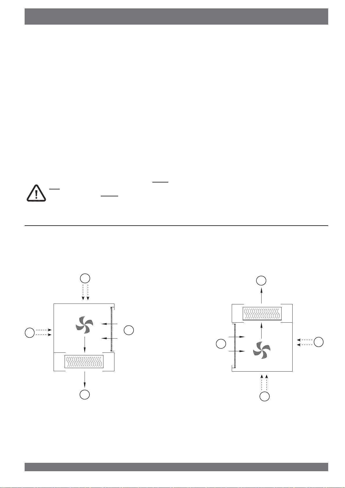
2.1
2.2
3
3.1
3.2
3.3
3.4
3.5
3.6
4
4.1
4.2
4.3
4.4
5
5.1
5.2
5.3
5.4
5.5
5.6
5.7
5.8
5.9
5.10
5.11
5.11.1
5.11.2
6
6.1
6.2
6.2.1
6.2.2
6.2.3
6.3
6.4
6.5
7
7.1
7.2
7.3
8
8.1
8.2
Delivery..........................................................
Scope of delivery ............................................
Accessories Elan ............................................
Application ....................................................
General ...........................................................
Upow and ownow versions.......................
Version...........................................................
Technical information Elan 10 2.0...................
Technical information Elan 16 2.0..................
Technical information Elan 25 2.1...................
Exploded view appliance (ownow version
imensions Elan 10 2.0 ownow .................
imensions Elan 16 2.025 2.1 Upow.........
Operation .......................................................
escription......................................................
Frost safety .....................................................
Outdoor air control .........................................
Extra Connectors ............................................
Installation .....................................................
Installation general .........................................
Placing the appliance .....................................
Conversion to Upow version .........................
Conversion to ownow version ....................
Water connections .........................................
Connecting ducts ............................................
Conversion from right-handed to left-handed
appliance .......................................................
Installation HRV on Elan ownow ................
Filter connections topbottom .........................
Cooling ...........................................................
Electric connections........................................
Connection of the power plug .........................
Ventilation switch ............................................
Display view ..................................................
General explanation control panel ..................
Operating mode ..............................................
Status system fan ...........................................
View output temperature ................................
Message text for operating mode ...................
Settings menu.................................................
Readout menu ................................................
Service menu..................................................
Putting into operation ..................................
Switching the appliance on and o .................
Setting the air owrate ....................................
Other settings installer ....................................
Faults .............................................................
Trouble shooting .............................................
isplay codes .................................................
1
1
2
3
3
3
4
4
5
6
7
8
8
9
9
9
9
9
10
10
10
10
11
11
11
12
13
13
13
14
14
14
15
15
16
16
16
16
17
18
19
20
20
20
20
21
21
21
7DEOHRIFRQWHQWV
9
9.1
9.2
10
10.1
11
11.1
11.2
11.2.1
11.2.2
11.3
12
12.1
12.2
13
Maintenance ................................................
Filter cleaning ...............................................
Maintenance .................................................
Electric diagrams........................................
Wiring diagram .............................................
Electric connections accessories .............
Connections connectors ...............................
Connection examples multiple switch...........
Multiple switch with lter indication ...............
Wireless remote control (without lter indica-
tion...............................................................
Connecting cooling .......................................
Service .........................................................
Exploded view ..............................................
Service articles .............................................
Setting values .............................................
eclaration of conformity ..............................
23
23
24
26
26
27
27
28
28
28
29
30
30
30
32
33