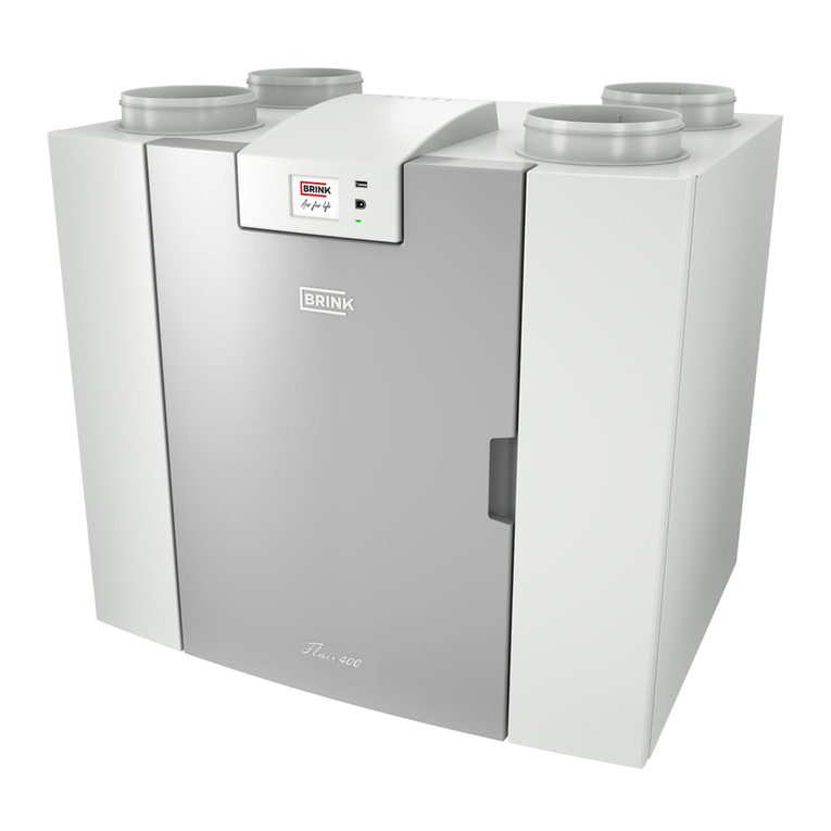
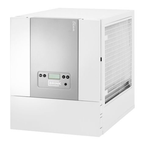
Brink ELAN 25 User manual

Installation instruction
Elan 25

STORE NEAR THE APPLIANCE
Country : UK
Installation instructions
Indirectly red air heater
Elan 25

Elan 25 1th edition May 2006
Tabel of contents
Chapter Page
Application
Standard version
1
1.1
1
1
Version
Upow and downow versions
Technical information
2
2.1
2.2
2
2
3
Design
Exploded view appliance
Function components
3
3.1
3.2
4
4
5
Operation
Outline description
LED indication system and operating panel
Ventilation switch
Cooling
4
4.1
4.2
4.3
4.4
6
6
6
8
8
Installation
Installation general
Placing the appliance
Free space around appliance
Regulations
Hot water connections
Right-handed and left-handed versions
Location heat recovery on Elan 25 Downow
Assembly
Connecting ducts
Overview connection options Elan 25 Downow R+L
Overview connection options Elan 25 Upow R+L
Condensate discharge
Electric connections
Connecting the power mains
Connecting cooling
Connecting the ventilation switch
5
5.1
5.1.1
5.1.2
5.1.3
5.1.4
5.1.5
5.1.6
5.2.1
5.2.2
5.2.3
5.2.4
5.3
5.4
5.4.1
5.4.2
5.4.3
9
9
9
9
9
9
9
10
11
11
12
13
14
14
14
15
15
Putting into operation
Switching the appliance on and off
Setting the output temperature
Setting the air quantity
Adjusting the air quantity at the grates
Other settings
Menu structure display
6
6.1
6.2
6.3
6.4
6.5
6.6
16
16
16
17
18
18
19
LED display system
General explanation display
Readout normal operation
Fault messages
7
7.1
7.2
7.3
21
21
22
23
Trouble shooting
Trouble shooting
Block diagram control and safety
8
8.1
8.2
25
25
26
Maintenance
User maintenance
Installer maintenance
9
9.1
9.2
27
27
28

Elan 25 1th edition May 2006
Tabel of contents
Electric diagrams
Wiring diagram
Connecting diagram
Connecting the ventilation switch
Connecting cooling
Fire safety
10
10.1
10.2
10.3
10.4
10.5
29
29
30
31
32
33
Service
Exploded view Elan 25 Upow
Exploded view Elan 25 Downow
Service kits
11
11.1
11.2
11.3
34
35
36
37
Chapter Page

Elan 25 1th edition May 2006

Elan 25 1th edition May 2006 1
Application Chapter 1
An appliance from the Elan 25 series is an indirectly red air
heater suitable for installations where a hot water supply is
available.
The appliance is also suitable for district heating.
The electric power consumption is reduced strongly because a
direct current fan is used. This fan has a high electric efciency
under all conditions of use.
It is possible to combine the Elan 25 Downow air heater with
the heat recovery unit Renovent HR.
The air quantity is automatically adapted to the outlet tempera-
ture of the appliance. All this results in very stable room tem-
perature, realising a perfect interior climate.
The appliance is available in a left-handed and a right-handed
version.
A right-handed version has the lter door on the right.
The appliance comes as standard with frost safety. This provi-
sion ensures that the heat exchanger cannot freeze.
When the temperature downstream of the heat exchanger
drops below 10 ºC, a switch ontact on the control unit is closed
(see section 10.2). That can for instance be used to switch on a
central heating pump to make (hot) water ow through the heat
exchanger. If the temperature should still drop below 5 ºC, the
system fan will be switched off.
The system fan will start running again if the temperature above
the heat exchanger becomes higher than 30 ºC.
The appliance comes ready to plug in. When it is placed, the
appliance must be connected to the system air channels, the
condensate discharge (applicable if a Renovent is mounted)
and the mains power.
It is possible to connect a ventilation switch.
This switch can be used to set the appliance in three different
modes, see section 4.3 and section 10.3.
1.1 Standard version

2 Elan 25 1th edition May 2006
The Elan 25 is available in a version with bottom output (Down-
ow) and in a version with top output (Upow)
2.1 Upow and downow versions
1 = Hot air
2 = Return air
Chapter 2 Version
5241-0
Figure 1: Basic diagram Elan 25
5562-0
Downow Upow

Elan 25 1th edition May 2006 3
Water ow [ºC]
Air input temperature [ºC]
Nominal Maximum
+16 +18 +20 +22 +16 +18 +20 +22
90/70 1,58 1,53 1,47 1,42 1,59 1,54 1,48 1,42
90/50 1,26 1,20 1,14 1,08 1,25 1,19 1,13 1,07
70/50 1,05 1,00 0,95 0,89 1,06 1,00 0,94 0,89
50/35 0,61 0,55 0,50 0,44 0,60 0,55 0,49 0,44
An air heater type Elan 25 is supplied for an installation were
hot water supply is available.
The appliance comes with the CE mark and complies with
the machine directive 89/392/EEC, the low-voltage directive.
73/23/EEC and the EMC directive 89/336/EEC.
2.2 Technical information
Nominal Maximum
Air displacement [m3/h] 1800 2200
Heating capacity [kW] 21,9 25,4
Water capacity [l/h] 956 1108
Waterside resistance [kPa] 2,24 2,94
Rated power fan [W] 315 460
Water ow [ºC] 70/50
Air input temperature [ºC] 18
Supply voltage [V~/Hz] 230/50
Maximum operating pressure exchanger [bar] 16
Water capacity exchanger [l] 3,26
Protection degree IP30
Water connection (female thread) [”] 1
Weight [ kg] 62
Correction factor heating capacity Elan 25 at other water and air input temperatures
Version Chapter 2

4 Elan 25 1th edition May 2006
5577-0
Figure 3: Location components Elan 25 R Upow
Chapter 3 Design
3.1 Exploded view appliance
Figure 2: Location components Elan 25 R Downow
5200-D
1 = Feedthrough condensate discharge heat recovery (if applicable)
2 = Feedthrough power cable 230 V
3 = Switchbox with control unit
4 = Operating panel
5 = Water connection (Return)
6 = Return temperature sensor
7 = Water connection (Supply)
8 = Filter door
9 = System fan
10 = Filter
11 = Heat exchanger
12 = System temperature sensor

Elan 25 1th edition May 2006 5
3.2 Function components
Design Chapter 3
1 Feedthrough condensate discharge Feedthrough condensate discharge if a heat recovery appliance is placed on the Elan
2 Feedthrough power cable Feedthrough 3-core power cable 230 V
3 Switchbox) Box with electronic components for various controls and monitoring for safe operation
of the appliance. It also contains the 20-pole connector for specic applications
4 Operating panel The operating panel has a display for indicating several operational situations, a reset
button for unlocking faults and keys for program settings
5 Water connection (Return) Connecting the water return
6 Return temperature sensor Sensor that measures the return air and, after switching on the frost safety, releases
the control again
7 Water connection (Supply) Connecting the water supply
8 Filter door Opening it gives access to the lter
9 System fan Arranges transport of air to the relevant rooms and sucks in the return air
10 Filter Filters dust particles from the air and protects the system fan from fouling
11 Heat exchanger This is where heat is exchanged to the air to be heated
12 System temperature sensor Sensor that controls the system fan rpm and, if necessary, activates the frost safety

6 Elan 25 1th edition May 2006
Chapter 4 Operation
4.1 Outline description
Elan 25 is a highly advanced air heater for which special atten-
tion has been paid to achieving the lowest possible energy con-
sumption. This is achieved through various electronic control
systems and an electronically operated direct current system
fan.
As a result of the application of a direct current motor in the
system fan, even at low mother rpm the electric efciency will
remain high.
A microprocessor control unit controls and monitors the safe
operation of the appliance. The system fan will steplessly
transport more or less air, dependent on the appliance output
temperature, which is measured continuously by the system
temperature sensor. The system temperature sensor is placed
under the heat exchanger.
The installer can set the maximum and minimum air quantity on
the appliance operating panel just like an air quantity for free
cooling. The electronic control in the system fan will ensure that
the preset air quantity remains maintained, until the pressure in
the air ducts has reached a preset maximum.
4.2 LED display system and operating panel
The Elan 25 has an operating panel on the outside. This oper-
ating panel can be used to call up and modify settings in the
control unit program. The operating panel has six keys and a
display (see gure 4).
Figure 4: View operating panel
4205-A
The display is composed of two sections; the left-hand section
shows the program or the step number and the right-hand sec-
tion, dependent on the program, a readout value, for instance
temperature, (indicated here is the operating situation with an
output temperature of 60 ºC).
Numbers higher than one hundred are indicated on the last
three 3 digits of the display (indicated is a temperature of
110 ºC at step number b).
Numbers below zero are indicated with a minus sign on the
second digit of the display (indicated is an outdoor temperature
of -20 ºC).
Display

Elan 25 1th edition May 2006 7
After adjusting the air quantity in the duct system, this initial
situation will be stored in the memory of the control unit (see
section 6.4, item 7). In addition, the permissible pressure in-
crease in the duct system can be entered into the memory, if
desired, by changing step no. 6 in the settings program into the
desired pressure(see section 6.4, item 8). When subsequently
the permissible pressure increase in the duct system is ex-
ceeded relative to the initial situation after adjustments or due
to closing dampers or grates or a fouled lter, the maximum air
output of the system fan will drop. That will make the pressure
in the duct sytem decrease to the original value.
When this control system is active, that will be indicated with a
‘o’ on the top half of the second digit of the display.
Keys
The six keys have the following functions:
MODE = selection key program,
STEP = increase the step number/programming,
STORE = store the setting,
+ = increase the setting,
- = decrease the setting,
RESET = reset key.
The ‘MODE’ key can be used to choose from a number of pro-
grams:
• operating situation,
(also refer to section 7.2)
• readout program (dot blinking),
(also refer to section 7.2)
• fault message (letter “F” and fault number
blinking simultaneously),
(also refer to section 7.3)
• setting program (dot lighted, step and readout value dis-
played alternately). (Only accessible for the installer after
entering the access code, with the exception of step 1 up
to and including 4, see basic settings appendix inspection
report)
As standard the display shows the standard operating situa-
tion, if a different program has been chosen, the appliance will
automatically return to displaying the operating situation after
some time.
In appendix “Inspection report” to these installation instructions,
the installer can record the values set in the setting program.
Operation Chapter 4
5306-A

8 Elan 25 1th edition May 2006
Chapter 4 Operation
4.3 Ventilation switch
If a ventilation switch is installed (connections 10, 11 and 12 on
the 20-pole connector), the user can set the number of operat-
ing situations:
4.4 Cooling
An Elan appliance can be equipped for cooling. For that pur-
pose an Elan cooling block must be placed in the air system,
a condensing unit must be connected to the cooling block and
a relay must be mounted on the Elan control unit (also refer to
section 6.3).
When cooling is switched on, the system will always be run-
ning at the air quantity cooling (setting step 4). For switching on
cooling, a connection must be made between terminals 8 and 9
on the 20-pole connector.
Position on 20-pole connector
10-12
Ventilation setting off (stand-by)
- System fan controlled by system temperature sensor; at no heat demand
the system fan is stopped
-
Comfort setting (regular)
- System fan controlled by system temperature sensor; at no heat demand
system fan continuously at minimum air quantity
10-11 Increased fan setting (high)
- System fan continuously on maximum preset air quantity

Elan 25 1th edition May 2006 9
Installation Chapter 5
5.1 Installation general
5.1.1 Placing the appliance
Before opening the appliance, rst pull the coloured lter door
from the clamp; then you can unscrew the front cover. Take into
account the following points when placing the air heater.
• Put the appliance as closely as possible to the water input/
output.
• Put the appliance as centrally as possible relative to the air
ducts.
• Put the appliance at an accessible place with sufcient room
for service.
• The hot water connections and the electric connections are
as standard at the left for an Elan 25 R; for an Elan 25 L
these connections are on the right.
• Put the appliance in a frost-free room.
• The air heater can be equipped with a free return.
This means that the installation room has an open connec-
tion with the rest of the dwelling.
• On a damp oor the air heater must be placed at a raised
level.
• Place the appliance vibration-free and level.
5.1.2 Free space around appliance
A number of requirements apply to the free space around the
appliance.
• Leave room between the appliance and the wall and the
ceiling.
• Always make sure there is a free space of at least 1 m at the
front of the appliance with a free headroom of at least 180
cm because of maintenance.
5.1.3 Regulations
The air heater Elan 25 must be installed in accordance with:
• The safety regulations for central heating installations,
• The relevant articles of the Building Decree
• The safety regulations for low-voltage installations,
• Any additional regulations of the local utilities.
• The installation regulations of the Elan 25.
5.1.4 Hot water connections
The heat exchanger in the air heater is connected with the aid
of a 1” connection.
When connecting the heat exchanger, be sure to hold the
1” connection to prevent it from rotating!
It is recommended to place stop cocks with couplings directly
on the outside of the appliance in the input as well as the input
lines.
5.1.5 Right-handed and left-handed versions
The Elan 25 is available in a right-handed as well as in a left-
handed version.
An Elan 25 with a lter door on the right is referred to as an
Elan 25 R, when the lter door is on the left the appliance is
referred to as an Elan 25 L.
Because the right-handed and the left-handed appliances have
different front panels, it is not possible to convert a right-hand-
ed appliance to a left-handed version afterwards. In addition,
when changing the right-handed version to a left-handed ver-
sion, the switchbox in the appliance is modied and moved and
the position of the temperate sensors is changed.

10 Elan 25 1th edition May 2006
Chapter 5 Installation
5.1.6 Location heat recovery on Elan 25 Downow
The Elan 25 Downow is already prepared for placing a Brink
heat recovery unit type Renovent HR on the appliance.
When placing the Renovent HR on an Elan 25 Downow, it
is assumed that the fronts of the two appliances are always
kept in line and that the lter doors of the two appliances are
mounted on the same side.
The connection “to dwelling” is connected at the top on the
Elan 25 Downow appliance.
The condensate discharge of the Renovent HR runs through
the Elan 25 Downow and comes out at the side of the Elan
25 Downow. Mount the condensate discharge carefully to
ensure that no condensate can enter the electronics of the
Elan 25D. The appliance comes with a set of plates needed to
seal a number of openings when a Renovent HR is installed.
First unscrew the square cover plate on top of the appliance.
The correct plate and the correct position are shown in gure 5.
Figure 5 : Placing sealing plates when a heat recovery unit is used
5319-0
Elan 25D R + Renovent HR Elan 25D L + Renovent HR
Elan 25D R + Renovent HR + Bypass Elan 25D L + Renovent HR + Bypass

Elan 25 1th edition May 2006 11
Installation Chapter 5
5.2.2 Connecting ducts
Standard hot air distribution boxes are available for the Elan
25 series. For an Upow these are placed on the appliance
and for a Downow they are placed under the appliance. The
hot air ducts are connected to the hot air distribution box.
Observe the following points when connecting the ducts.
• Install a control damper in every branch of the hot air distri-
bution box or the main duct.
• Insulate all hot air ducts including the grate shoes and the
exterior air duct.
• Apply a moisture barrier around the insulation mate-
rial to prevent takeup of moisture from the surrounding
air.
• Always lay out return ducts in such a manner that they do
not become sound bridges, so no straight connections be-
tween two rooms.
• Connecting the return
Connect the return duct to the return air or the installation
room. An acoustic return plate is available for an appliance
with open return.
• Provide the exterior air connection with a control damper
and connect it to the return duct.
More detailed information can be found in the guidelines
stated in the Brink design manual and assembly manual.
5.2.1 Assembly
Assembly of the hot air distribution box, and the air ducts is
described in the Brink assembly manual.

12 Elan 25 1th edition May 2006
Figure 7: Connection points Elan 25D L
5305-A
A = Feedthrough condensate discharge heat recovery
(Only if applicable)
B = Feedthrough power cable
C = Water connection (return)
D = Water connection (supply)
E = Input opening return air
F = Output opening
G = Connection heat recovery (only if applicable)
H = Feedthrough condensate discharge heat recovery
(Only if applicable)
5.2.3 Overview connection options Elan 25 Downow R+L
Figure 6: Connection points Elan 25D R
5242-B
Chapter 5 Installation

Elan 25 1th edition May 2006 13
5.2.4 Overview connection options Elan 25 Upow R+L
Installation Chapter 5
Figure 9: Connection points Elan 25 L
5560-0
B = Feedthrough power cable
C = Water connection (return)
D = Water connection (supply)
E = Input opening return air
F = Output opening
Figure 8: Connection points Elan 25 R
5561-0

14 Elan 25 1th edition May 2006
5.3 Condensate discharge Renovent HR
The Elan 25 Downow is already prepared for placing a Ren-
ovent HR on the Elan 25. The condensate discharge of the
Renovent HR must be carried outside through the Elan 25
Downow. This feedthrough is always at the same side as the
hot water connections, so for an Elan 25 R Downow the con-
densate discharge is fed out of the appliance on the left. The
condensate discharge pipe Ø20 is fed outside through a grom-
met; select the most suitable grommet; cut an opening into the
grommet for feeding through.
For a correct operation of the appliance, the condensate dis-
charge must have an open connection to the drain system,
provided with a funnel and an additional water seal or siphon
(see gure 7). The condensate discharge of the appliance must
never be sealed.
Without any objection the condensate can be carried off through
the interior drains.
Discharge to the gutter is not permitted because of the risk of
freezing.
Warning
When the appliance has been placed, the siphon must be
lled with water.
Figure 7: Connecting the condensate discharge to the interior drains
5321-A
5.4.1 Connecting the power mains
The mains plug must be connected to a power mains 230 V~50
Hz with earth. The connection must be an earthed wall socket.
The wall socket must be accessible at all times. It is recom-
mended to connect this supply to a separate end group, with
fuse 16 A(T) inert. All mains wiring must be in accordance with
the current I.E.E. Regulations, or the appropriate standards of
your country and Must be installed by a suitably qualied per-
son.
Chapter 5 Installation

Elan 25 1th edition May 2006 15
Installation Chapter 5
5.4.2 Connection cooling
If the Elan 25 is equipped with cooling, the control wires for
the condensing unit must be connected to no.1 and no.2 of
the 20-pole connector of the switchbox (see section 10.4).
The Elan Series with cooling is described in more detail
in het installation instructions with cooling.
The installer does have to place the cooling relay in the
relay socket provided in the switchbox.
A separate air quantity can be set for cooling (see section
6.3).
5.4.3 Connecting the ventilation switch
It is also possible to connect a ventilation switch to the switch-
box (see section 10.3). It allows the users to set a number of
operating situations (see section 4.3).
Table of contents
Other Brink Heater manuals
Popular Heater manuals by other brands

Lasko
Lasko Designer 6405 Important instructions & operating manual

Trotec
Trotec TIH 350+ operating manual

Kroll
Kroll P32 instruction manual

Ceanothe
Ceanothe DECOWATT Installation and operation manual

EUROM
EUROM 307030 instruction manual

Process Technology
Process Technology SH Series Installation and operation manual