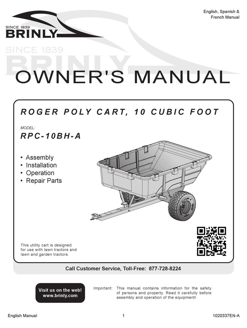
Brinly PCT-101BH User manual

11008577ALL-E
Call Customer Service, Toll-Free: 877-728-8224
Important: This manual contains information for the safety
of persons and property. Read it carefully before
assembly and operation of the equipment!
Visit us on the web!
www.brinly.com
POLY CART, 10 CUBIC FOOT
MODEL:
PCT-101BH
PCT-101BHC
PCT-101BHC-A
PCT-101BHEXP
This utility cart is designed
for use with lawn tractors and
lawn and garden tractors.
English Manual
French Manual

21008577ALL-E
==================================================================================================
English Manual
INTRODUCTION AND SAFETY
CUSTOMER RESPONSIBILITIES
- Please read & retain this manual. The instructions will enable to assemble and maintain your product properly.
- Please carefully read and observe the SAFETY SECTION of this manual.
- Follow a regular schedule in maintaining and caring for your Brinly-Hardy product.
CONGRATULATIONS on your new Brinly-Hardy Cart! This accessory has been designed, engineered and manufactured
to give you the best possible dependability and performance.
Should you experience any problem you cannot easily remedy, please do not hesitate to contact our knowledgeable
customer service department toll-free at 1-877-728-8224. We have competent, well trained technicians to help you with
the assembly and use of your Cart.
TABLE OF CONTENTS
Introduction, Safety and
Required Tools ............... 2 - 4
Parts ....................... 5 - 6
Assembly ................... 7 - 12
USE AND CARE
Operation ................. 12 - 14
Adding Side-Stakes ......... 14 - 16
Service ...................... 17
Accessories .................. 17
Warranty ..................... 18
TOOLS REQUIRED
FOR ASSEMBLY:
=============================
• 1/2” Wrench (x2)
• 9/16” Wrench (x2)
• Flat Tip Screw Driver
• Pliers
• Gloves
SPECIFICATIONS
============================================
Maximum Towing Speed ................................. 5 mph
Bed Capacity ............................................ 10 Cu. Ft.
Maximum Load ............................................. 650 lbs
Tire; Size ................................................... 15" x 6"
The safety labels shown in this section are placed in important
areas on your product to draw attention to potential safety
hazards.
On your product safety labels, the words DANGER, WARNING
and CAUTION are used with the safety-alert symbol. DANGER
identifies the most serious hazards.
The operator’s manual also explains any potential safety
hazards whenever necessary in special safety messages that
are identified with the word, CAUTION, and the safety-alert
symbol.
SAFETY LABELS
=================================================
This symbol will help to point out important safety
precautions throughout this manual. It means:
ATTENTION! BECOME ALERT! YOUR SAFETY
IS INVOLVED.

31008577ALL-E
==================================================================================================
English Manual
SAFETY
GENERAL SAFETY NOTES
Towing speed should always be slow enough to maintain
Caution should be taken when towing and/or using any attachment. This attachment combined with the weight distribution,
turning radius, and speed of towing vehicle can result in severe injury or death to operator, damage to towing vehicle,
and/or attachment if not used properly. Follow all towing safety precautions noted in the towing vehicle owner’s manual,
including the following precautions:
Reduce towed weight when operating on slopes.
sudden changes in speed, directions, or turning.
If you start and stop suddenly on hills, you may lose steering
WARNING
AVOID INJURY FROM EXPLOSION
RIDERS CAN FALL OFF AND BE KILLED

1008577ALL-E
==================================================================================================
English Manual
STOP
Installation Questions?
DON’T GO BACK TO
THE STORE!
any reason including emptying the attachment.
This attachment is intended for use in lawn care and home
any high speed applications.
towing speed.
damage should be repaired before restarting and operating the
equipment.
Replace all worn or damaged safety and instruction decals.
Keep all nuts, bolts and screws tight.
KEEP RIDERS OFF TOWED
ATTACHMENT AND TOWING VEHICLE
and turns.
attachment being operated in an unsafe manner.
TOWING VEHICLE AND TOWING SAFELY
operating.
counterweights or wheel weights as described in the towing
PROTECT THOSE AROUND YOU
Before you operate any feature of this attachment or towing
Keep children, bystanders and pets at a safe distance away
while operating this or any attachment.
behind for bystanders.
POLY CART SPECIFIC SAFETY INSTRUCTIONS
GENERAL SAFETY NOTES
SAFETY

51008577ALL-E
==================================================================================================
English Manual
COMPONENT VIEW AND REFERENCE LIST
1
3
6
14 14
20
19
2
7(x10)
10 (x10)
(x2)
(x2)
8
9+
(x8)
9
+
8
14
+
13
14
+
13
24
12
5
15
23
18
17
22
(x2)
9
(x2) 7
+
8
16
11
21
4
Ref. Description Part Number Qty.
21 Towbar B-6296-2 1
Ref. Description Part Number Qty.

61008577ALL-E
==================================================================================================
English Manual
DO NOT RETURN PRODUCT IF YOU ARE MISSING PARTS.
HARDWARE IDENTIFIER
Illustrations on this page
are to scale for faster
during assembly.
Hitch
D-146P . . . . . . . . . . . . . . . .
18
. . . . . . . . . . . . . . . . . . . . . . . . .
B-3861
12
Retaining Ring, E
. . . . . . . . . . . .
13
B-4305
. . . . . . . . . . . . .
8
30M1000P
. . . . . . . . . . . . . . . . . .
16
B-6299
. . . . . . . . . . . . . . .
11
B-1675P
5/16” . . . . . . . . . . . . . . . . .
9
40M1000P
5/16” . . . . . . . . . . . . . . .
45M1111P
10
. . . . . . . . . . . . . . . . .
B-6298
15
. . . . . . . . . . . . . . . . . . . . . . . . . . . . . . . . . . . .
20M1016P
7
B-6300
17
. . . . . . . .
A few extra parts will be leftover that are not used on this model.
EXTRA PARTS:

1008577ALL-E
==================================================================================================
English Manual
Please disregard the extra washers in Hardware Panel 2, they are for a dierent model.
ASSEMBLY
x8
7
10
Assembly Step 1
8
9
8
+
9
10
+
7
20
1
Install Axle Support
20
1
1
710
9
8
NOT
x2
7
10
Assembly Step 2 8
9
8
+
9
10
+
7
1
6
NOT
Install Lock Bracket
6
6
1
7
10
From the outside, add a 5/16"
9
8
similarly, as illustrated.

1008577ALL-E
==================================================================================================
English Manual
4
21
the notch in the foot pedal oriented
towards the raised tongue on
the drawbar.
See illustration.
4
21
ASSEMBLY
4
21
Starred edge of the waSher needS to be facing the Spring.
15
21
4
1615
NOTE: Foot pedal can be adjusted slightly while installing
bolt (15). This will help to align the bolt with the hole on the
other side of the drawbar.
Assembly Step 3-B
4
21
16
15
16
Assembly Step 3-A

91008577ALL-E
==================================================================================================
English Manual
ASSEMBLY
Starred edge of the waSher needS to be facing the Spring.
Assembly Step 3-C
154
4
1615
1521
NOTE: Foot pedal can be adjusted slightly while installing bolt (15).
This will help to align the bolt with the hole on the other side of the
drawbar.
4
21
16
16
15
Assembly Step 3-D
16
16
11
15
15
11
16

10 1008577ALL-E
==================================================================================================
English Manual
ASSEMBLY
Assembly Step 4
17
hole at the base of the foot
4
17
21
21
17
x2
12
18
NOTE: For initial use, you may need to tap or push the hairpin cotter
into place by applying some pressure with a tool.
5
21
75
21
Secure beneath the drawbar (21) with
two 5/16 in. lock washers (9) and 5/16
in. nuts (8).
5
7
18
12
7
8
9
Install Clevis
Assembly Step 5
21
4
9
8
+

11 1008577ALL-E
==================================================================================================
English Manual
19
13
ASSEMBLY
Assembly Step 6
21
19
20
19
21
20
NOTE: A light coating of grease or oil on axle will
aid in inserting the axle through the axle support.
13
NOTE: You may need to tap or push the retaining ring
into place by applying pressure with a tool.
19
14
14
3
21
19
21
c
b
a
d
14
193
14
Please disregard the extra
bushings in Hardware Panel 6,
they are for a different model.
Please disregard the extra bushings in Hardware Panel 6, they are for a dierent model.
NOTE: Tighten all hardware installed on Steps 1 and 2.

12 1008577ALL-E
==================================================================================================
English Manual
ASSEMBLY
Assembly Step 7
Gently ip
the cart over.
SPECIFICATIONS
............. 10 cu ft
......... 5 mph
MAXIMUM ........
Tire pressure may be reduced to increase
wheel traction or to reduce shock, although
it should not be reduced to below 70% of the
maximum rated pressure.
DIMENSIONS ..........
Assembly is complete!
MAINTENANCE
all fasteners for tightness.
impair its function and safety.
and, if necessary, lubricate with oil.
For rust appearing on painted surfaces, sand lightly and paint
affected area with enamel.
USE AND CARE
MODEL:
PCT-101BH CART
USE & CARE SECTION

13 1008577ALL-E
==================================================================================================
English Manual
REMOVING THE CART
(See towing vehicle operator’s manual).
1812
5
1218
CAUTION: AVOID INJURY!
12
18
INSTALLING THE CART
(See towing vehicle operator’s manual).
5
125
1218
CAUTION: AVOID INJURY! Keep body parts
18
12
5
USE AND CARE
CAUTION:
CAUTION: AVOID INJURY! Keep body parts
away from under Bed when dumping or closing.
(See towing vehicle operator’s manual).
3. Raise the bed carefully into the full dump position.
5. Keep body parts from under the Bed when closing.
CAUTION:
(Example: load
set at rear of cart).
UNLOADING THE CART
STORAGE
CART SHOULD BE STORED IN A DRY PLACE.

1008577ALL-E
==================================================================================================
English Manual
USE AND CARE
WEIGHT CAPACITY
adding ballast to the towing machine.
weight is required, add this weight at or forward of the rear
Keep riders out of cart.
AVOID OVERFILLING THE CART
cart to a capacity that is comfortable for you to dump.
CAUTION:
operator MUST BE MORE than the weight of
cart and load.
EXAMPLE:
----------------
MODEL WEIGHT
(empty)
----------------
DIY: DIRECTIONS FOR
CUSTOM-BUILT SIDE STAKES
Read a
nd follow the operating
rails to increase the weight capacity of your cart. (Refer to
your cart manual for cart weight capacity).
the cart.
arms, or head as these could become caught and cause
-
machine being operated in an unsafe manner.
table.
Inspect wood for rot and fasteners for rust before use and
replace rotted, rusted, or worn parts as needed.
SAFETY NOTES:

15 1008577ALL-E
==================================================================================================
English Manual
USE AND CARE
DIY: DIRECTIONS FOR CUSTOM-BUILT SIDE STAKES, Continued
SHOPPING LIST /
MATERIALS NEEDED:
Ref. Description: Qty.
Long Pressure
Treated Wood:
1
2 2
3
Hardware:
20
5
6
20
Material Notes:
- It is recommended that all
fasteners are plated grade 5.
- All material listed can be
purchased at a standard
hardware store.
Step 1.
1
1
rail installation.
9/32 Diameter
33-1/2”
13-1/8
4”
10-3/16
42-1/4”
5-3/4 13-1/8 13-1/8 13-1/8
8” 13-1/2”
9/32 Diameter
2”
3-3/4”
9/32 Diameter9/32 Diameter
4”
1
Step 2.
2
Holes must be aligned as illustrated here:
9/32 Diameter
33-1/2”
13-1/8
4”
10-3/16
42-1/4”
5-3/4 13-1/8 13-1/8 13-1/8
8” 13-1/2”
9/32 Diameter
2”
3-3/4”
9/32 Diameter9/32 Diameter
4”
2
Step 3.
3
Holes must be aligned as illustrated here:
9/32 Diameter
33-1/2”
13-1/8
4”
10-3/16
42-1/4”
5-3/4 13-1/8 13-1/8 13-1/8
8” 13-1/2”
9/32 Diameter
2”
3-3/4”
9/32 Diameter9/32 Diameter
4”
3

16 1008577ALL-E
==================================================================================================
English Manual
USE AND CARE
DIY: DIRECTIONS FOR CUSTOM-BUILT SIDE STAKES, Continued
4
5
1
56
1
4
5
5
6
3
2
Step 4.
Building the
Stake Side Rails
here.
Step 5.
Drilling Location (if needed)
OR
The hole must be
centered right to left on the cart
pocket and 1-3/4” up from the
pocket bottom.
Step 6.
Securing the Stake Side Rails
illustrated here.
7
7
7
77
7

1008577ALL-E
==================================================================================================
English Manual
Additional accesories are also available in our Parts Store online: shop.brinly.com
Magnetic Hitch Pin
pin can replace a regular cotter
180-Degree Full Dump Kit
OPTIONAL ACCESSORIES
QUALITY CONTINUES
WITH QUALITY SERVICE
SERVICE
call
Toll-Free: 877-728-8224
www.brinly.com
Email: customerservice@brinly.com
QR code.
ONLINE
BRINLY.COM
USE AND CARE
NOTES

CARTS
If this equipment is being used in a commercial application and / or for
multiple properties, the warranty is 90 days after purchase for all parts.
warrantY period:
See applicable parts listed below.
Standard / Residential Use:
............. 2 years
.......................... 2 years
.................... 90 days
All other normal wear parts or component failures
will be covered on this product for a period of 90 days.
-
uct has been assembled, operated, and maintained in accordance
damage because of other peril or natural disaster.
-
-
pressly limited to the replacement or repair, at our option, of parts
how to obtain SerVice:
-
No implied warranty, including any implied warranty of mer-
chantability of tness for a particular purpose, applies after
the applicable period of express written warranty above as to
the part as identied below. No other express warranty whether
written or oral, except as mentioned above, given by any per-
son or entity, including a dealer or retailer, with respect to any
product, shall bind Brinly-Hardy Co. During the period of the
warranty, the exclusive remedy is repair or replacement of the
product as set forth above.
The provisions as set forth in this warranty provide the sole
and exclusive remedy arising from the sale. Brinly-Hardy Co.
shall not be liable for incidental or consequential loss or dam-
age including, without limitation, expenses incurred for substi-
tute or replacement lawn care services or for rental expenses to
temporarily replace a warranted product.
consequential damages, or limitations on how long an implied warran-
or to others and their property arising out of the misuse or inability
This limited warranty shall not extend to
anyone other than the original purchaser or to the person for whom
it was purchased as a gift.
This limited warranty lasts as long you own your product purchased
Coverage terminates once you sell or
otherwise transfer the product.
-
are the original purchaser of the product, purchased the product from
limited warranty.
How state law relates to this warranty:
iMportant:
date of manufacture determined by the serial number manufacturing
of the original product, and any warranty on the replaced parts will
The limited warranty set forth below is given by Brinly-Hardy Company with respect to new
merchandise purchased and used in the United States (its possessions and territories) and Canada.
This limited warranty does not provide coverage
in the following cases:
c. Transportation and/or labor charges.
d. The warranty does not include commercial and/or rental use.
Other manuals for PCT-101BH
1
This manual suits for next models
3
Other Brinly Outdoor Cart manuals