manuals.online logo
Brands
  1. Home
  2. •
  3. Brands
  4. •
  5. Brizo
  6. •
  7. Plumbing Product
  8. •
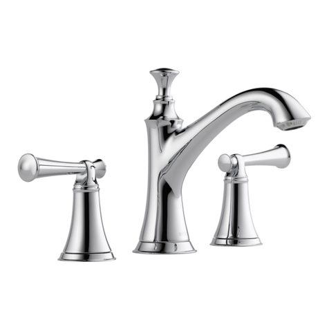
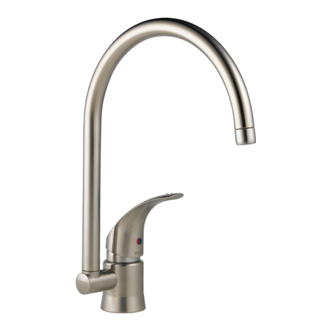
  9. Brizo Trevi Cross 6516017 User manual

Brizo Trevi Cross 6516017 User manual

Models/Modelos/Modèles
6516017
Series/Series/Seria
TrevitCross
Writepurchasedmodelnumberhere.
Escriba aquíelnúmero del modelocomprado.
Inscrivez lenuméro demodèleici.
Youmay need/Usted puedenecesitar/
Articlesdontvouspouvez avoirbesoin:
For easyinstallationofyour
BRIZOtfaucetyouwill need:
*ToREAD ALL theinstructionscompletely before
beginning.
*ToREAD ALL warnings,care,and maintenance
information.
*To purchasethe correctwater supplyhook--up.
Parainstalaciónfácil desullave
BRIZOtusted necesitará:
*LEERTODASlasinstruccionescompletamente
antesde empezar.
*LEERTODOSlosavisos,cuidados,einformación
demantemiento.
*Comprarlasconexionescorrectaspara elsuministro
deagua.
Pourinstaller votre robinetBRIZOt
facilement, vousdevez :
*LIRE TOUTESlesinstructionsavantdedébuter.
*LIRE TOUSlesavertissementsainsiquetoutes
lesinstructionsdenettoyage etd’entretien.
*Acheterlebon raccordementnécessaire pour
l’alimentationeneau.
12690.00 11.05d
1
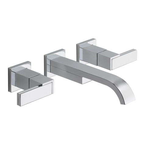
TWO HANDLE WIDESPREAD LAVATORY FAUCETS
MEZCLADORPARA SUPERFICIEHORIZONTAL
DE LAVABO
MELANGEUR SUR PAROIHORIZONTALE POUR LAVABO
3mm
t
Note:The back edge of the faucetbody
mustbe atleast1 1/2inchesfromthe
backsplashonwall in orderto allowthe
lift rod tofunction properly.
Nota:La orilla posteriordelcuerpo de la
llave de agua debe estara porlomenos
1 1/2 pulgadasdelprotectorde pared
en la pared para permitirque la barra de
levantefuncione apropiadamente.
Note:Le rebord arrièreducorpsdu ro-
binetdoitsetrouveràaumoins1 1/2 po
du dosseretsurlemurpourque latirette
puissefonctionnercorrectement.
r
CSAB125
ASMEA112.18.1
ICC/ANSIA117.1
r
2
12
1
INSTALLATIONOFSPOUT
Note:When drilling mounting holesforthespout it isrecommended
that theholesize mustbeaminimumof1--1/4”(32 mm).
A.Makesureo--ring (1)isin place as shown.
B.Insertspoutassemblyintomounting surface.
C.Slipfixing washer(2)overmounting stud and securewith nut(3).
Option:If mounting surface isuneven,usesiliconesealantunder
faucet in place ofgasket.
INSTALACIÓN DEL CAÑO
Nota:Cuando taladrelosagujerosparalainstalación delsurtidorse
recomiendaque el tamaño delagujerosea deun mínimo de1--1/4”
(32 mm).
A.Aseguresequelajuntatórica (1)estéposicionada comosemuestra en
eldibujo.
B.Introducirlallaveporelorificio delasuperficiedemontaje.
C.Situarlapieza defijación (2)enlavarillaroscadayfijarmediantela
tuerca (3).
Opcional:Si lasuperficiedemontajeno estálisa,aplicarun cordón de
silicona enlugardelajuntadegoma.
INSTALLATIONDUBEC
Note:letrou pourlebec doit avoiraumoins1--1/4po(32 mm);
assurez--vousqu’il estdu bon diamètre enleperçant.
A.Assurez--vousquelejoint torique(1)esten place.
B.Placez lerobinetdansletrou d’installation.
C.Placez larondelledefixation (2)surletoulon fileté etfixez--la avec
l’écrou (3).
Option:Si lasurface d’installation est inégale,utilisez un matériau
d’étanchéitédesiliconesouslerobinetaulieudujoint.
3
2
12690.00
2
3
2
9
7
4
10
8
6
5
1
11
INSTALLATIONOFVALVEASSEMBLY.
Note:When drilling mounting holesforsidevalvesit isrecommendedthatholesize
mustbeaminimumof1--1/8”(29 mm).
A.Assemblemounting partstosidevalve(1):nut(2)washer(3)and gasket(4).
B.Insertvalve assembly, into holefromunderneathmounting surface.Screwon top
flange(5)and tightenfirmly. Place valvein desired position and hand tightennut(2).
C.Install stempiece (6)and attach handlebase(7)totop flange(5)butdonot tighten
until handlehasbeenlinedupand nut(2)hasbeentightened. Install handle(8)with
valveinclosed position. Securehandlewithscrewand attach plug (11).
D.Place handlein desired position by turning valve assembly, and securevalve
assemblybytightening nut(2)firmly. Tighten handlebase(7)by hand only.
E.Connectflexibleoutlethoses(9)and inlethoses(10)totheportsmarked”IN”&
”OUT”on sidevalves,and tospout.Tighten nutsfirmly(Hex:23 mm)butdo notover
tighten.
INSTALACION DE LASLLAVES.
Nota:Cuando taladrelosagujerosparalainstalación delasválvulaslaterales sere-
comiendaque el tamaño delagujerosea deun mínimo de1--1/8”(29 mm).
A.Ensamblelaspiezasparalainstalación enlaválvula alcostado (1): latuerca (2)la
arandela(3)ylajunta(4).
B.Introduzca elensambledelaválvula enelagujero pordebajo delasuperficiedonde
estáhaciendo lainstalación. Atornille elrebordesuperior(5)yaprietefirmemente.
Coloquelaválvula enlaposición deseadayaprietelatuerca amano(2).
C.Instalelapieza dela espiga(6)yfijelabasedelamanija(7)alrebordesuperior(5)
perono aprietehastaquelamanijaseha alineadoylatuerca (2)seha apretado. Instale
lamanija(8)con laválvula en posición cerrada.Fijelamanija con el tornilloyfije el
tapón (11).
D.Coloquelamanija enlaposición deseadagirando elensambledelaválvula,yfijela
válvula apretando latuerca (2)firmemente.Aprietelabasedelamanija(7)sóloamano.
E.Conectelasmanguerasflexiblesdelaguadesalida(9)ylasmanguerasdelaguade
entrada(10)alastomasmarcadas”IN”y”OUT”enlasválvulasdeloscostados,yal
surtidor.Aprietelastuercasfirmemente(Hex:23 mm)peronoaprietedemasiado.
INSTALLATION DE L’ASSEMBLAGEDESOUPAPE
Note:letrou pourles soupapesdoit avoiraumoins1--1/8po(29 mm);
assurez--vousqu’il estbon diamètre enleperçant.
A.Assemblez lespiècesdemontagedelasoupape(1): l’écrou (2),larondelle(3)et le
joint(4).
B.Introduisez lasoupapedansletrou parledessousdelasurface demontage.Vissez la
collerettesupérieure(5)etserrez--lafermement.Placez lasoupapedanslaposition
voulue estserrez l’écrou àlamain(2).
C.Montez larallonged’obturateur(6)etfixez labasedelamanette(7)àla collerette
supérieure(5),maisévitez deserrer tantquevousn’avez paspositionnélamanette et
serrél’écrou (2).Montez lamanette(8)alorsquelasoupape estfermée.Immobilisez la
manetteàl’aidedelavisetfixez lebouchon (11).
D.Placez lamanettedanslaposition voulue entournant lasoupape etfixez lasoupape
enserrant l’écrou (2)fermement.Serrez labasedelamanette(7)àlamainseulement.
E.Raccordez lestuyaux souplesdesortie(9)et lestuyaux souplesd’entrée (10)aux
orificesdes soupapesidentifiésparlesmots“IN”et“OUT”ainsiqu’au bec.Serrez les
écrousfermement(cléhexagonale23 mm),maispasexcessivement.
3
34
12
3
1/2”(12.70mm)IPS
4
Forfixedspout
Para caño fijo
Pourbec fixé
12690.00
HAGALASCONEXIONESALASLÍNEASDEAGUA:
Escoja conexionesde1/2”IPS:
(1)Tubo montantedebola(tuberíade cobre3/8”D.E.)o
(2)Conexión I.P.S.de1/2”parallaves.
Utilice lastuercasde acoplamientoincluídas(3)con lostubosmontantes
debola(1).Utilice dosllavesfijascuando apriete(4).Noapriete
demasiado.
MAKECONNECTIONSTOWATERLINES:
Choosehook--upsfor1/2”I.P.S.connections:
(1)Ball noseriser (3/8”O.D.coppertubing),or
(2)1/2”I.P.S.faucetconnector.
Usethe enclosedcoupling nuts(3)withtheball noserisers(1).
Usetwowrenches(4)whentightening.Do notovertighten.
RACCORDEZ LESTUYAUX D’EAU CHAUDEETD’EAU
FROIDE.
Choisissez desraccordscompatibles1/2”IPS:
(1)tubes--raccordsàportée sphérique(tube encuivre3/8”d.e.),ou
(2)raccordsderobinet1/2”IPS.
Sivousutilisez destubes--raccordsàportée sphérique(1),servez--vous
desécrousderaccordementfournis(3).Utilisez deux clés(4)pourserrer
lesraccords.Prenez gardedetrop serrer.
OPTIONAL:
INSTALL SWIVEL LIMITATION
A.Unscrewthescrew(4)and removethespout(3).
B.Fit thetwoswivel limitation elements(1 and 2)intherecess on
thestud.(Element1-- plasticlimitation,element2-- metalbushing).
C.Install theswivelspout(3)on thestud.
D.Install thescrew(4)for fixing thespout tothemetalbushing.(2)
OPCIONAL:
INSTALACIÓN DEL BLOQUEODEL CAÑO GIRATORIO
A.Desatornillarel tornillo(4)y dejarelcaño (3).
B.Montarlasdosunidadesdebloqueo(1-- 2)enlaranura enelracor
(Unidad1-- bloqueo deplástico,unidad2-- bloqueometálico).
C.Fijarelcaño giratorio(3)enelracor.
D.Apretarel tornillo(4)paralafijación delcaño enelbloqueo
metálico(2).
FACULTATIF:
INSTALLEZ LALIMITATIONDUMOUVEMENTPIVOTANT
A.Dévissez levis(4)etenlevez lebec (3).
B.Montez lesdeux plaquesdeserrure(1et2)enreces surlatubulure
(Elément1–arrêten plastique,élément2–arrêt métallique).
C.Montez lebec pivotant(3)surlatubulure.
D.Montez levis(4)pour fixation du becàl’arrêt métallique(2).
4
2
1
3
4
5
15
14
13
912
11
16
2
1
3
4
5
6
7
8
10
17
E.Colocarlapieza deplástico(8)dentro delcuerpo (9)yroscareste enla
válvula(3).Nota:Elorificioroscado (16)debe estarorientado haciala
llave.Empujarhacia abajolaválvulayreajustarlaspiezascolocadasen
elpasoD.
F.Colocarel tapón (2)dentro delaválvula(3).Colocarlapieza negra(11)
enlavarilla(12)asulado corto.Colocartambiénlapieza deplástico
(13)enlavarillaporsulado largo.
G.Introducirlavarilla(12)enelcuerpo (9).Apretarlatuerca de
acoplamientoalorificioroscado.
H.Unirlavarilla(12)al tornillo de apriete(14).Introducirelaccionador
(17)atravésdelcuerpo delallavedentro del tornillo de apriete(14).
Apretarel tornillo(15)ycomprobarelbuenfuncionamiento delsiste-
ma.
INSTALACIÓN DEL DESAGÜEAUTOMÁTICO.
A.Quitar elprotectordeplástico(1)yeltapón(2)dela válvula(3).
B.Desmontarelracordedesagüe(10)delcuerpo (9)aplicando Teflónâa
la zonaroscadadel tubo.Roscaréste(10)denuevo enelcuerpo (9).
C.Colocarlajuntadegomablanca (4)enlaválvula(3).Sepuedeutilizar
un cordón desiliconasisedesea.Introducirlaválvula enelorificio de
desagüedel lavabo/fregadero,etc
D.Colocarlajuntadegomablanca (5),con su parte cónica hacia arriba,
ylajuntadefibra(6)enlaválvula(3)pordebajo del lavabo/
fregadero.Roscarlatuerca (7)enlaválvula(3)peronoapretar
definitivamentetodavía.
POP--UPINSTALLATION
A.Removeplasticstoppercap(1)and stopper(2)fromflange(3).
B.Removetailpiece (10)frombody (9)and applyTeflonâtapetothreads
on tailpiece.Screwtailpiece (10)backinto body (9).
C.Slidewhitegasket(4)ontoflange(3).(Siliconemay beusedtoreplace
gasket ifdesired.) Insertflangeintosink.
D.Push black gasket(5),conesideup,and fiberwasher(6)ontoflange
(3)fromundersink.Screwnut(7)ontoflange(3)butdo notsecurein
place yet.
E.Place whiteplasticseal(8)into body (9)and screwbody (9)ontoflange
(3).Note:Pivot(16)mustface faucet.Pull assembly downand tighten
nut/washer/gasketon flange(3).
F.Place stopper(2)intoflange(3).Place blackseal(11)onto pivotrod
(12)fromshortend and pivotnut(13)from long end.
G.Insertpivotrod (12)into body (9).Tighten pivotnut.
H.Attach pivotrod (12)toclamp(14).Install liftrod (17)through faucet
body intoclamp(14).Tightenscrew(15)and check operation of
stopper.
INSTALLATION DU VIDAGEAUTOMATIQUE
A.Enlevez le chapeau deprotection(1)etlebouchon(2)delabonde
àbouchon(3).
B.Enlevez leraccord devidage(10)du corps(9)etappliquez unebande
adhésivedeTéflonâaufiletagedu raccord devidage.Vissez le
raccord devidage(10)surle corps(9)denouveau.
C.Faitesglisserlejointblanc(4)surlabondeàbouchon (3).(On peut
éventuellementutilisersilicone aulieudujoint).Passez labonde à
bouchon danslelavabo.
D.Poussez lejointnoir(5),avec le côté conique en haut,et lejointen
fibre(6)surlabondeàbouchon (3)dedessousdu lavabo.Vissez
l’écrou (7)surlabondeàbouchon (3)sansfixerencore en place.
E.Placez lejointen plastiqueblanche(8)dansle corps(9)etvissez le
corps(9)surlabondeàbouchon (3).Note: lemembredu pivot(16)
doit êtretournéverslerobinet.Tirez en basl’assemblage etserrez
l’écrou et lesjoints surlabondeàbouchon (3).
F.Placez lebouchon (2)danslabondeàbouchon (3).Placez lejointnoir
(11)surlatigehorizontale(12)àl’extrémité courte et l’écrou (13)à
l’extrémitélongue.
G.Placez latigehorizontale(12)dansle corps(9).Serrez l’écrou du
pivot.
H.Fixez latigehorizontale(12)àlapièce deserrage(14).Installez la
tirettedevidage(17)àtraversle corpsdu mitigeuretdanslapièce de
serrage(14).Serrez levis(15)etcontrôlez lefonctionnementdu
bouchon.
12690.00
5
67
1
FLUSHYOUR SYSTEM
Remove aerator(1)and turn bothfaucethandles(2)tothefull open
position.Turn on hotand coldwatersuppliesand flushwaterlinesfor
oneminute.
Important: Thisflushesawayany debristhatcouldcausedamageto
internalparts.
PURGAR SUSISTEMA
Quite elaireador(1)y girelasdosmanijasdelallave(2)alaposición
completamente abierta.Abralos suministrosde agua calienteyfríay
deje correrelaguaporlaslíneasporun minuto.
Importante:Estolimpia cualquierescombro quepueda causardaño a
laspartesinternas.
RINCEZ LE ROBINET
Enlevez l’aérateur(1)et tournez lesdeux manettes(2)en position
d’ouverturemaximale.Rétablissez l’alimentation eneauchaude eten
eaufroide et laissez coulerl’eau pendantuneminute.
Important: Lefait delaissercoulerl’eau permetd’évacuerlescorps
étrangersquipourraientabîmerlescomposantsinternesdu robinet.
2
2
CHECKCONNECTIONS
Checkall connectionsforleaks.Re--tightenifnecessary,but
do notovertighten.
VERIFICAR UNIONES
Verificartodasuniones sihayfugas.Apretardenuevo,si
necesario,no aprietedemasiado.
CONTROLEZ LESASSEMBLAGES
Contrôlez touslesassemblages s’il yadesfuites.Reserrez si
nécessaire,maisprenez gardedenepastrop serrer.
12690.00

Other Brizo Plumbing Product manuals

Brizo Riviera 6115080 User manual

Brizo

Brizo Riviera 6115080 User manual

Brizo BELO 63052LF User manual

Brizo

Brizo BELO 63052LF User manual

Brizo SOLNA Series User manual

Brizo

Brizo SOLNA Series User manual

Brizo Baliza Series User manual

Brizo

Brizo Baliza Series User manual

Brizo Mystix RP103316BNXL User manual

Brizo

Brizo Mystix RP103316BNXL User manual

Brizo Sotria T65851LF Series User manual

Brizo

Brizo Sotria T65851LF Series User manual

Brizo Siderna SENSORI T66T080 User manual

Brizo

Brizo Siderna SENSORI T66T080 User manual

Brizo Quiessence 85521 User manual

Brizo

Brizo Quiessence 85521 User manual

Brizo 65014LF Series User manual

Brizo

Brizo 65014LF Series User manual

Brizo VUELO 64255LF Series User manual

Brizo

Brizo VUELO 64255LF Series User manual

Brizo Odin T65875LF LHP Series User manual

Brizo

Brizo Odin T65875LF LHP Series User manual

Brizo Charolotte 65885LF Series User manual

Brizo

Brizo Charolotte 65885LF Series User manual

Brizo ATAVIS 88742 User manual

Brizo

Brizo ATAVIS 88742 User manual

Brizo Siderna 65880LF User manual

Brizo

Brizo Siderna 65880LF User manual

Brizo MultiChoice T60P006-GLLHP User manual

Brizo

Brizo MultiChoice T60P006-GLLHP User manual

Brizo TALO 64003LF User manual

Brizo

Brizo TALO 64003LF User manual

Brizo Venuto 64970LF User manual

Brizo

Brizo Venuto 64970LF User manual

Brizo Baliza Series User manual

Brizo

Brizo Baliza Series User manual

Brizo Charlotte 65685LF-ECO User manual

Brizo

Brizo Charlotte 65685LF-ECO User manual

Brizo Levoir 696398 Series User manual

Brizo

Brizo Levoir 696398 Series User manual

Brizo MultiChoice VETTIS T60288 User manual

Brizo

Brizo MultiChoice VETTIS T60288 User manual

Brizo Litze 65035LF ECO Series User manual

Brizo

Brizo Litze 65035LF ECO Series User manual

Brizo Virage 68430 User manual

Brizo

Brizo Virage 68430 User manual

Brizo Frank Lloyd Wright T60P022-PCLHP User manual

Brizo

Brizo Frank Lloyd Wright T60P022-PCLHP User manual

Popular Plumbing Product manuals by other brands

Moen SANI-STREAM 8797 manual

Moen

Moen SANI-STREAM 8797 manual

Grohe Allure Brilliant 19 784 manual

Grohe

Grohe Allure Brilliant 19 784 manual

Cistermiser Easyflush EVO 1.5 manual

Cistermiser

Cistermiser Easyflush EVO 1.5 manual

Kohler Triton Rite-Temp K-T6910-2A installation guide

Kohler

Kohler Triton Rite-Temp K-T6910-2A installation guide

BEMIS FNOTAB100 Installation instruction

BEMIS

BEMIS FNOTAB100 Installation instruction

Hans Grohe ShowerTablet Select 700 13184000 Instructions for use/assembly instructions

Hans Grohe

Hans Grohe ShowerTablet Select 700 13184000 Instructions for use/assembly instructions

Akw Stone Wash Basin Installation instructions manual

Akw

Akw Stone Wash Basin Installation instructions manual

Enlighten Sauna Rustic-4 user manual

Enlighten Sauna

Enlighten Sauna Rustic-4 user manual

Moen ShowHouse S244 Series quick start guide

Moen

Moen ShowHouse S244 Series quick start guide

Sanela SLWN 08 Mounting instructions

Sanela

Sanela SLWN 08 Mounting instructions

Franke 7612982239618 operating instructions

Franke

Franke 7612982239618 operating instructions

Heritage Bathrooms Granley Deco PGDW02 Fitting Instructions & Contents List

Heritage Bathrooms

Heritage Bathrooms Granley Deco PGDW02 Fitting Instructions & Contents List

Tres TOUCH-TRES 1.61.445 instructions

Tres

Tres TOUCH-TRES 1.61.445 instructions

STIEBEL ELTRON WS-1 Operation and installation

STIEBEL ELTRON

STIEBEL ELTRON WS-1 Operation and installation

Miomare HG00383A manual

Miomare

Miomare HG00383A manual

BELLOSTA revivre 6521/CR1 quick start guide

BELLOSTA

BELLOSTA revivre 6521/CR1 quick start guide

American Standard Heritage Amarilis 7298.229 parts list

American Standard

American Standard Heritage Amarilis 7298.229 parts list

BorMann Elite BTW5024 quick start guide

BorMann

BorMann Elite BTW5024 quick start guide

manuals.online logo
manuals.online logoBrands
  • About & Mission
  • Contact us
  • Privacy Policy
  • Terms and Conditions

Copyright 2025 Manuals.Online. All Rights Reserved.