BRN DISPLAY 500 User manual

DISPLAY 500
USER MANUAL

Contents
1. About the user manual ..................................................................................................... 2
2. Material and external dimensions .................................................................................... 2
Real product and dimension figure :(unit: mm)............................................................................2
3. Function
summar ........................................................................................................... 3
4. Button
function ................................................................................................................ 5
5. Normal operation ............................................................................................................. 6
(1). On/off function ....................................................................................................................... 6
(2). Displa
interface ..................................................................................................................... 8
(3). Turn on
(off) backlight ......................................................................................................... 10
(4). PAS level selection ............................................................................................................... 11
(5). Batter indication .................................................................................................................. 11
(6). Error code
definition ............................................................................................................. 12
6. General setting ............................................................................................................... 12
(1) Unit speed setting,km/h and mph switching..........................................................................12
7. Maintenance .......................................................................................................................... 12
WARNINGS ................................................................................................................................ 13
1.About the user manual
Dear users,
To ensure better performance of our ebike, please read through the 500
instruction carefull before using it. We will inform ou of all the details, including
the installation and function setting of the displa with the most concise words.
Meanwhile, the specification will also help ou to solve possible malfunction.
2.Material and external dimensions
500 products use the LCD screen, double side printed board , n lon buckle, ABS
material shell. Under the temperature ranging from -20℃to 60℃, the shell
material can ensure the good mechanical performance of the products.
Real product and dimension fi ure :(unit: mm)

Figure 2

3. Function summary
500 is a Multifunctional displa .
500 function Summar (Figure 3-1)
◆Kilometers or miles scale selection
◆Current speed indication
◆Rotational informations: Total
distance indication, Riding
distance indication, Time
(Hours:Minutes)
◆Backlight indication (switch backlight)
◆PAS level selection, Error code definition
◆Batter capacit indication
Figure 3-1
Di )


Display during use(without backlight (figure 3-3)
Figure 3-3
Display during use(with backlight (figure 3-4)
Figure 3-4
The displa could be the left and right hand t pe according with bike manufacturer
choice.
4. Button function
500 has two buttons including ON/OFF/UP and SET/DOWN.(figure 4)

Figure 4
Pressing the ON/OFF/UP button for 3 seconds ou can turn the s stem on
Once the s stem is ON, pressing shortl the UP button means to shift to higher
assistance levels.
Pressing the UP button for 3 seconds shut the s stem off.
Pressing the SET/DOWN button shortl means to shift to lower assistance
levels.
Pressing the SET/DOWN button for more than 5 seconds ou can use the 6Km/h
function if ou are in 0 assistance level.
Pressing UP and DOWN buttons together, shortl , ou can light up displa and
bic cle lights if the are connected to the electrical s stem.
Pressing UP and DOWN buttons together, for more than 10 seconds, ou will
access programming area with sensitive data under password.
Password is given to manufacturers onl .

5.Normal operation
To switch on the s stem first ou have to switch one the batter . Than ou can
operate the commands on the displa trough buttons.
The s stem will start in 0 assistance mode. It means that the s stem will not start
if ou push the pedals. To start to have assistance ou have to select manuall the 1
or the upper assistance mode.
(1) On/off function
Clicking button, the displa starts to work and provides the power to the
s stem.
You can hold button for 3 seconds to turn off the s stem power. The displa is
no longer asking power from batter and the leakage current is less than 2µA.
When ou press the button for more than 5 seconds, there will be 1.3V-3.5V
signal sent to the controller, it can push the ebike reaching 6km/h. This function can
be used in two occasions:
a) the rider doesn
’
t want to push hard on pedals at start.
b) The rider is not on the bike and wants to push the bike, while walking, with
out an effort.
Both kind of use will affect the milage of the bike since the s stem will use Power
provided b the batter
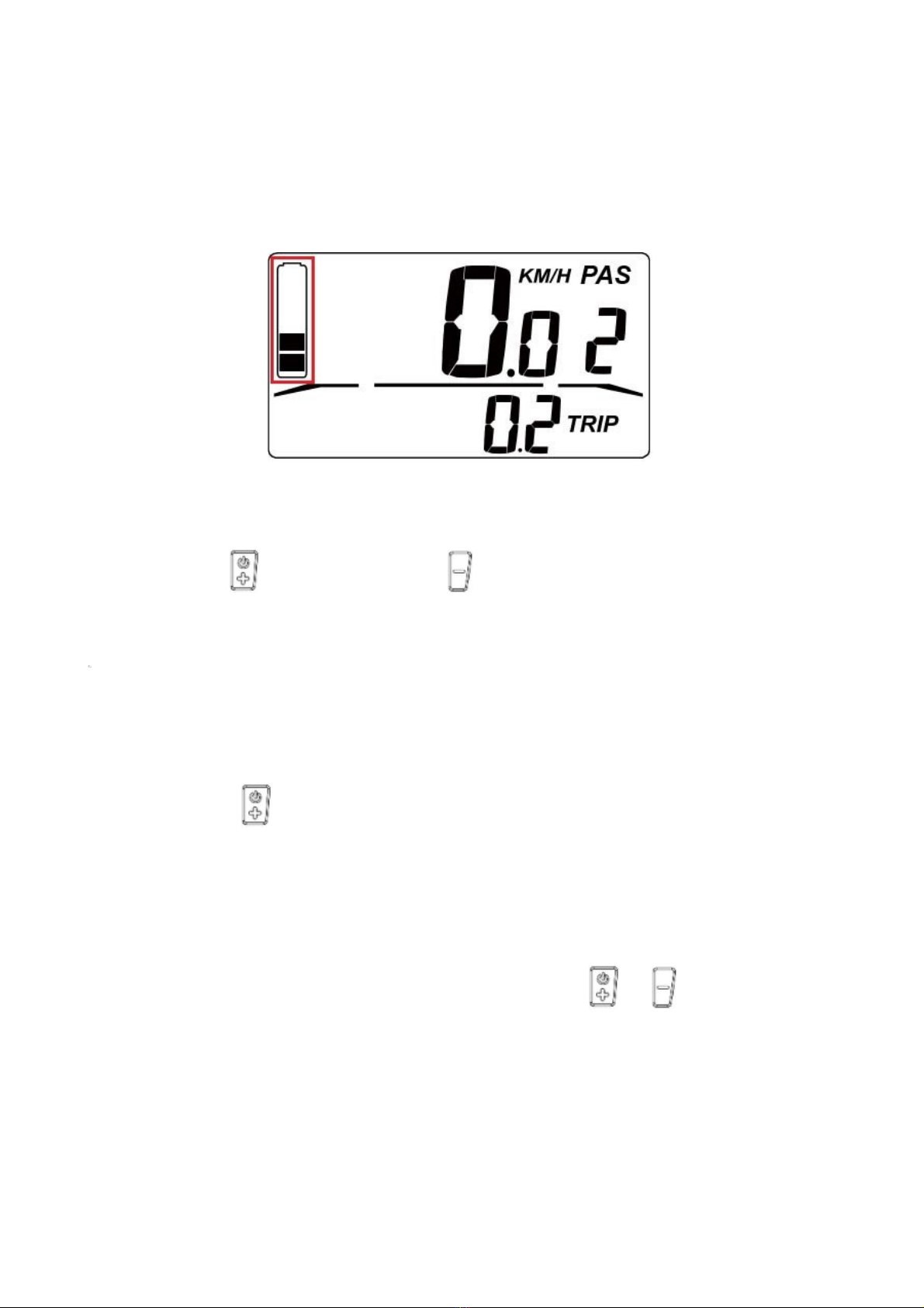
(2) Display interface
Displa will show the current speed of the ebike , total distance , trip
distance,pedal assistance level, batter capacit .
Current speed is shown in figure 5-1.

Figure 5-1
Distance is shown in figure 5-2 as ODO, Distance from the last Switch On is
showed as TRIP.
Figure 5-2
Pedal assistance level is shown in figure 5-3.
Figure 5-3

Batter capacit is shown in figure 5-4.( The remaining power 2 out 5,it
means 40% of the batter capacit is remained)
Figure 5-4
(3)Turn on (off) backli ht
Clicking button together with , and after the displa initializing for 3s ,
the light starts to work. Holding the two buttons for 3 seconds once the lights
are On,the backlight is turned off . If a front and/or a rear light is attached to the e-
bike s stem of the bike the back light functions will be applied also to the connected
lights.
You can hold button for 5S to turn off the power of the s stem.
(4) PAS level selection
When the displa is power on , you can shortly click or button to adjust
the PAS level which will change the output power of the motor. The PAS level is
normally set at level 0 when you power on the display , you can adjust it from 0 to
,the operation process is shown in figure 5-5.

Figure 5-5
(5) Battery indication
There will be five bars shown on the screen if the batter capacit is ver high
enough. The less bars will show on the screen if the capacit of the batter is less.
When the batter is almost dead, the last bar will flash. You need to charge the
batter immediatel . As shown in figure 5-6.
Figure 5-6
(6)Error code definition
When the ebike drive s stem fails, it will stop working ,and the displa will show
the error code on the screen automaticall . The error code will not stop showing on
the screen until the problem is solved. The reason for the error is shown in the
attachment of error code definition table.
Displa error code is shown in figure 5-7.

6.General setting
Figure 5-7
(1) Speed unit settin , km/h and mph switchin
When the displa is power on, ou can hold buttons for 10s to enter into
the speed unit settings interface. You can change the speed unit to kilometers or miles
b clicking or button.( It will return to the main operation interface if ou
doesn
’
t click an button in 5s). As shown in figure 7-1 (Default setting is km/h if
there is no special requirement)
Figure 6-1
7.Maintenance
The 500 displa and related electrical Kit do not require special maintenance from
the user.
It is maintenance free for the final user except periodical cleaning from mud or dust.

Batter of the s stem should be charged once the displa show that it is at lower level
or when the s stem shut off because out of current.
Charge periodicall (at least ever 2 weeks) the batter .
Keep the batter at least 50% charged when the bike will be left for long time
not used. Batteries that will remain not charged at the lowest level for long time
ma loose performaces or even die.
Use a proper batter charger to charge the batter . For a 36V lithium batter a charger
with following specifications is required:
- Max 42V output charging tension
- Min 2A max 4A output charging current.
- 100/240Vac input voltage.
- Costant Current/Costant Voltage functioning s stem (specific for Lithium
batteries). Plug the charger to a Vac socket compliant with the voltage and
morpholog of the charger itself to charge the batter .
Use a matching connector to connect charger to batter . Do not tr to modif a not
matching one to connect the batter .
If the user warn a problem during the ride of the bike, it is important to bring the
vehicle to a service center.
Before an maintenance operation please be sure that the power of the s stem is off.
Periodicall check that bolts, tightenings and electrical connections are not loose.
Periodicall proceed with cleaning of installed electrical components with a wet
towel and not with high pressure water.
WARNINGS
- Do not use the electrical s stem in a dangerous or not intended use
- Do not expose the electrical s stem to heav rain or snow
- Pa attention to use correct connector matching if connector removal is required
- On connectors there are indications about correct plug in position. Please do not
force connectors during the matching.
- If ou want to wash electrical components, please use a wet towel once the
s stem is off.
- Charge at least ever 2 weeks our batter with appropriate charger.
- Charge our e-bike with the s stem switched off and in a dr place.
- This instruction has been translated from the original documentation written in
Mandarin Chinese. All cares to be compliant with original meaning have been taken.
Table of contents
Other BRN Bicycle Accessories manuals