Broadata Communications Link Bridge LBC-HDBT-Lite-Tx User manual

LBC-HDBT-Lite-Tx/Rx
LINK BRIDGETM HDBASET
HDMITRANSMISSION SYSTEM
BCI reserves the right to make changes to the products described herein without
prior notice or consent. No liability is assumed as a result of their use or
application. All rights reserved.
©2013 Broadata Communications, Inc.

LBC-HDBT-LiteUser’sManual
LinkBridgeTM HDbaseT HDMITransmission System
SAFETY INSTRUCTIONS AND
COMPLIANCE DECLARATIONS
PLEASEOBSERVETHEFOLLOWINGSAFETY
PRECAUTIONS
SURGEPROTECTION DEVICERECOMMENDED
This product contains sensitive electrical components that may be
damaged by electrical spikes, surges, electric shock, lightning strikes,
etc. Use of surge protection systems is highly recommended in order
to protect and extend the life of your equipment.

LBC-HDBT-LiteUser’s Manual
LinkBridgeTM HDbaseT HDMITransmission System
Broadata Technical Support, (800) 214-0222
4
TABLE OF CONTENTS
1.0 PRODUCT DESCRIPTION .............................................5
2.0 OPERATION CONTROLS AND FUNCTIONS ...............6
2.1 TRANSMITTER FRONT AND REAR PANELS...............6
2.2 RECEIVER FRONT AND REAR PANELS.......................7
3.0 SERIAL CONTROL..........................................................8
3.1 D-SUB 9 PIN ASSIGNMENT ...........................................8
3.2 IR BLASTER CABLE PIN ASSIGNMENT.......................9
3.3 IR RECEIVER CABLE PIN ASSIGNMENT ....................9
4.0 MAINTENANCE AND TROUBLESHOOTING..............10
4.1 MAINTENANCE .............................................................10
4.2 TROUBLESHOOTING ..................................................10
5.0 SPECIFICATIONS..........................................................12
6.0 SERVICE PROCEDURE ...............................................13
6.1 REPLACEMENT POLICY .............................................13
6.2 RETURN AND REPAIR SERVICE .................................13
7.0 LIMITED WARRANTY....................................................14

LBC-HDBT-LiteUser’sManual
LinkBridgeTM HDbaseT HDMITransmission System
1.0 PRODUCT DESCRIPTION
The LBC-HBDT-Lite-Tx/Rx with HDMI video and RS-232 over Single
CAT5e/6transmitterandreceiversetcansenduncompressedaudio/video
over a single run of CAT5e/6 cable up to 60m with PoH (Power over
HDBT)featureandtheaddedbenefitofcontrolthroughthebuilt-inRS-232
andIR ports.
Features
• HDMI 1.4 with 3D, 4k×2k support, HDCP & DVI Compliant
• SupportsCECbypass
• Simultaneoustransmission of uncompressed data over a
single60m/CAT5e/6 cable
• Uncompressedvideo 1080p, 60 Hz, 36-bit
• Audiosupport up to 7.1CH & Dolby TrueHD, DTS-HD
• RS-232withbaudrateupto115200/sec
Package Contents
• 1×HDMIto CAT5e/6(withIR/RS-232/PoH) Transmitter
• 1×CAT5e/6toHDMI (withIR/RS-232/PoH) Reciever
• 1×IRBlaster
• 1×IRReceiver
• 1x3.5to RS-232 female adapter
• 1x3.5toRS-232maleadapter
• 1×24V/1.25ADC PowerAdaptor
• OperationManual

LBC-HDBT-LiteUser’s Manual
LinkBridgeTM HDbaseT HDMITransmission System
Broadata Technical Support, (800) 214-0222
6
2.0 OPERATION CONTROLS AND FUNCTIONS
2.1 Transmitter Front and Rear Panels
1. RS-232 In: Connect to a PC or laptop with D-Sub 9 pin male
cablefor the transmission of RS-232 commands.
2. IR 2 Extender: Connect tothe suppliedIR receivercables forIR
signal reception. Ensure that remote being used is within the
directline-of-sight of theIRextender.
3. IR 1 Blaster: Connect to the supplied IR blaster cable for IR
signaltransmission. PlacetheIR blasterin direct line-of-sightof
theequipment to be controlled.
4. HDMI In: ConnecttoHDMI sourceequipment suchas aDVD or
Blu-rayplayer.
5. DC 24V: Plug the24VDCpowersupplyintotheunit andconnect
theadaptor to anACoutlet. Only one sideof power needs tobe
connectedto activate both transmitterand receiver.
6. Link LED: The yellow LED will illuminate when both the input
andoutput signals are connected.
7. Power LED: This blue LED will illuminate when the device is
connected to a power supply.
8. CAT5e/6Out:Connectto therecieverunitwith aSingle CAT5e/6
cable for tranmission of all data signals.
LBC-HDBT-LiteUser’sManual
LinkBridgeTM HDbaseT HDMITransmission System
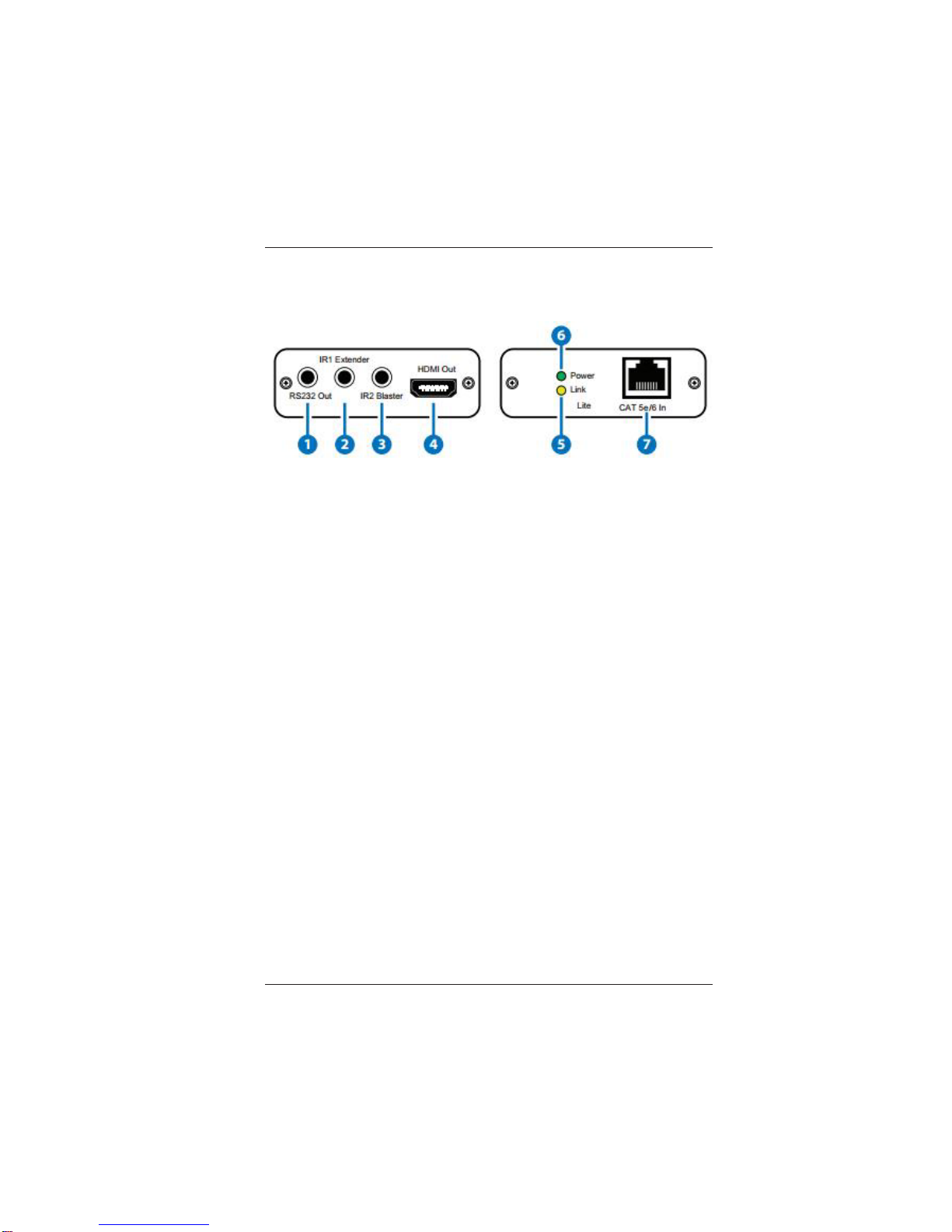
2.2 Receiver Front and Rear Panels
1. RS-232 Out: Connect to the device that is to be controlled (via
D-Sub9 pin female cable) by RS-232 commands.
2. IR 1 Blaster: Connect to the supplied IR blaster cable for IR
signal transmission. Place the IR blaster in direct line of sight
of the equipment to be controlled.
3. IR 2 Extender: Connect to the supplied IR receiver cables for
IRsignal reception. Ensurethatremote being usedis within the
directline-of-sightofthe IR extender.
4. HDMI Out: Connect to a HDMI source equipment such as a
DVDor Blu-ray player.
5. Link LED: The yellow LED will illuminate when both the input
andoutput signals are connected.
6. Power LED: This blue LED will illuminate when the device is
connected to a power supply.
7. CAT5e/6 In: Connect tothe receiver unit witha Single CAT5e/6
cable for tranmission of all data signals.

LBC-HDBT-Lite User’s Manual
LinkBridgeTM HDbaseT HDMITransmission System
Broadata Technical Support, (800) 214-0222
8
3.0 SERIAL CONTROL
3.1 D-Sub Pin Assignment
Pin
1
2
3
4
5
6
7
8
9
Define TX/RX
N/C
TxD/RxD
RxD/TxD
N/C
GND
N/C
N/C
N/C
N/C
LBC-HDBT-LiteUser’sManual
LinkBridgeTM HDbaseT HDMITransmission System
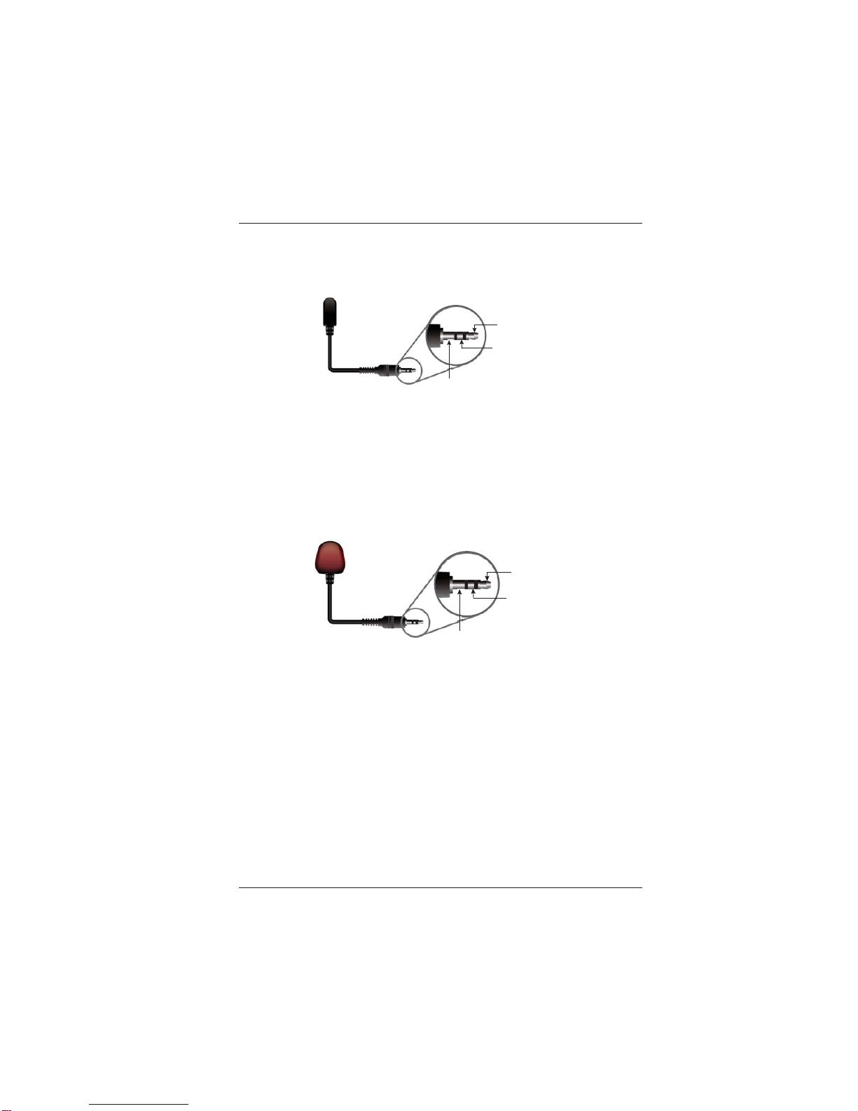
3.2 IR Blaster Cable Pin Assignment
3.3 IR Receiver Cable Pin Assignment
IR Blaster Power 5V
IR Blaster Signal
NC
IR Receiver
IR Signal
Power 5V
Grounding

LBC-HDBT-Lite User’s Manual
LinkBridgeTM HDbaseT HDMITransmission System
Broadata Technical Support, (800) 214-0222
10
4.0 MAINTENANCE AND TROUBLESHOOTING
4.1 Maintenance
Thereis no operator maintenance other then keepingtheunits
clean. However, observe the following light indicators to make
sure that the unit is working properly:
4.2 Troubleshooting
If the LBC-HDBT-Lite units do not operate properly after
installation,check forpossible cablebreaks, looseconnections,
and incorrect cable connections. If problems persist that may
be fiber related, contact BCI at 1-800-214-0222 for further
assistance.
For electrical problems, perform the following troubleshooting
procedures:
1. If the POWER indicator is OFF, check for the following:
a. The line cord is plugged into the unit and your outlet
haspower.
2. If the POWER indicator is ON, but the Link indicator is
OFF, check for the following:
a. Makesure the appropriate cables are being used.
b. Cableand cable connectors are not broken.
c. For each unit, the transmit (TX) cable is connected to
theother unit’s receiver (RX).

LBC-HDBT-LiteUser’sManual
LinkBridgeTM HDbaseT HDMITransmission System
3. If the POWER indicator and Link indicator are ON, but
the channels are not operating, then:
a. Checktoseethattheattacheduserequipmentisturned
on.
b. Both ends of the link are connected to the
corresponding equipment and to the same
correspondingchannel port.
c. Cable connections at both channels are securely
fastened to each connector. Turn the power off, then
back on to reset the link.
This manual suits for next models
1
Table of contents
Other Broadata Communications Microphone System manuals


