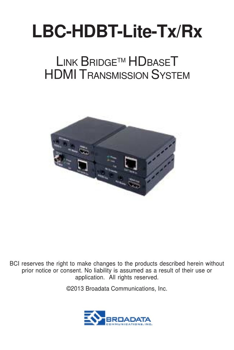
Broadata Communications LINKBRIDGE LBO-DP12-R-2F User manual

LINKBRIDGE™ FIBER OPTIC / DISPLAY PORT
TRANSMISSION SYSTEM
BCI reserves the right to make changes to the products described herein without
prior notice or consent. No liability is assumed as a result of their use or application.
All rights reserved.
©2019 Broadata Communications, Inc.
LBO-DP12-T-2F / LBO-DP12-R-2F

LinkBridge Fiber Optic/DisplayPort Transmission System User Manual (LBO-DP12-T-2F / LBO-DP12-R-2F)
SAFETY INSTRUCTIONS AND COMPLIANCE DECLARATION
PLEASE OBSERVE THE FOLLOWING SAFETY PRECAUTIONS AS OUR PRODUCTS
CONTAIN
CLASS I LASER PRODUCTS
WARNING
Do not disconnect the fiber optic connector while the unit is powered up.
Exposure to laser radiation is possible when the laser fiber optic connector is
disconnected while the unit is powered up.
Although the fiber optic connectors in this product emit only Class 1 energy that is
below the levels considered to be hazardous, one should never stare directly into
a fiber optic connector or an unconnected fiber end unless one can be certain that
no exposure to laser energy could occur.
CAUTION
This manual is intended for use by trained service personnel. The use of controls,
making adjustments, or performing operations other than those specified may
result in hazardous radiation exposure.
The following label or equivalent is located on the surface of laser products. This
label indicates that the product is classified as a CLASS 1 LASER PRODUCT.
SURGE PROTECTION DEVICE RECOMMENDED
This product contains sensitive electrical components that may be damaged
by electrical spikes, surges, electric shock, lightning strikes, etc. Use of surge
protection systems is highly recommended in order to protect and extend the life
of your equipment.

SAFETY INFORMATION
LinkBridge Fiber Optic/DisplayPort Transmission System User Manual (LBO-DP12-T-2F / LBO-DP12-R-2F)
Do not use this device near water/liquids. This device should not be exposed to dripping and
splashing or liquids.
Clean only with dry cloth.
Do not use solvents such as paint thinners and acetone to clean external casing. Such
agents will remove any labels on the device.
Do not block any ventilation openings.
Do not install near any sources of intense heat such as radiation, boilers, or other equipment
that produce heat
Not intended for use/storage in close proximity of critical medical supplies such as those that
might come into direct contact with patients or medical sta.
Protect the power cord from being pinched or damaged at receptacles and the point of exit
from the device.
Only use attachment /accessories specified by manufacturer. If you have any questions
about the compatibility of an accessory, contact your dealer.
In case liquid spillage on device, unplug mains power cord and contact your dealer. Continu-
ous use in this case may result in fire or electric shock.
To reduce the risk of electric shock, do not touch connectors with wet hand.
Only power with the marked voltage on the device. Any other voltage can cause fire or elec-
tric shock.
Do not use the device if an abnormality occurs. If any smoke or odor becomes apparent, un-
plug the power cord and contact your dealer. Do not try to repair the device yourself.
Avoid using physically damaged devices. If your device metal housing is seriously physically
damaged, the internal components may function abnormally. Contact your dealer.
Do not install the device in an area heavy with dust or constant high humidity. Operating the
device in this case may result in fire or electric shock.
Only use supplied power supply. For a list of other compatible power supplies, contact your
dealer.
Install this device in a secure location where it cannot be easily pushed or knocked over.

TABLE OF CONTENTS
LinkBridge Fiber Optic/DisplayPort Transmission System User Manual (LBO-DP12-T-2F / LBO-DP12-R-2F)
PRODUCT DESCRIPTION
OPERATION CONTROL AND FUNCTIONS
TRANSMITTER / RECEIVER
CONNECTION DIAGRAM
SYSTEM SETUP
SPECIFICATIONS
MAINTENANCE AND TROUBLESHOOTING
SERVICE PROCEDURE
REPLACEMENT POLICY
RETURN AND REPAIR SERVICE
LIMITED WARRANTY
5
6
6
8
9
10
11
12
13
13
14
1.0
2.0
2.1
3.0
4.0
5.0
5.1
5.2
6.0
7.0
8.0

5
PRODUCT DESCRIPTION
LinkBridge Fiber Optic/DisplayPort Transmission System User Manual (LBO-DP12-T-2F / LBO-DP12-R-2F)
The LBO-DP12 Series is a high performance, low cost, small form-factor, directly pluggable
Fiber Optic 4K DisplayPort Transmission System (Transmitter and Receiver). It transmits 4K
(4096x2160) at 60Hz DisplayPort video signals over (2) LC Multimode fibers to provide full
uncompressed video. This unique fiber optic transmission system allows video signals to be
extended up to 200m at 4K60, YCbCr 4:4:4. Simply plug-in the DisplayPort adapter to your
source and/or displays and fiber connectors and the system is ready to use.
FEATURES:
• Extend 4K DP signals up to 200 meters over two (2) LC multi-mode fibers (OM3)
• Video Resolutions up to 4K2K @ 60Hz, YCbCr 4:4:4 or RGB
• Fully uncompressed video and audio provides zero loss of quality
• Oers total maximum bandwidth of 21.6Gbps (5.4 Gbps per lane)
• Supports Dual-mode DP (DP++)
• Includes two (2) micro USB cables for the transmitter and receiver
• Certification CE/FCC, UL IT, Laser Safety Class 1
• Supports multi-stream transport (MST)
• Tx/Rx can be powered by phantom power or by USB power
IDEAL FOR
• Medical Imaging
• Military- Command & Control Rooms, Simulators,
• Showrooms & Demo Rooms
• Hotel Lobby Information Displays
• Public Commercial Displays
PACKAGE CONTENTS
• 1×LinkBridge™Fiber Optic/DisplayPort Transmitter
• 1×LinkBridge™Fiber Optic/DisplayPort Receiver
• 1×DisplayPort Extender Cable (Male to Female DP)
• 2×Micro USB to USB Cable
• 1×User Manual
SYSTEM REQUIREMENTS
• DisplayPort source equipment such as a media player, video game console or set-
top box.
• DisplayPort receiving equipment such as HDTVs, monitors or audio amplifiers.
• The use of Broadata Fiber Optic cables is highly recommended. (F2-P-OM3-XXX)

6OPERATION CONTROL AND FUNCTIONS
LinkBridge Fiber Optic/DisplayPort Transmission System User Manual (LBO-DP12-T-2F / LBO-DP12-R-2F)
TRANSMITTER
1
LBODP12T2F
2
34
5
DisplayPort Connector: Connect to DisplayPort input/source equipment such as
a media player, game console or set-top box.
Power LED: This LED will illuminate blue when the Transmitter is connected
to a DisplayPort source and receiving a signal.
Status LED: This LED will blink three (3) times when a connection is made to
the display side. When the connection is made, this LED will
blink again.
LC Connector: Connect Fiber Optic cables with duplex connectors for
extension to the Receiver
USB Port: Connect Micro USB Cable to provide power to the units*
* Unit can also be powered using 3.3V from Pin #20 on the
DisplayPort Interface
1
2
3
4
5

7
OPERATION CONTROL AND FUNCTIONS
LinkBridge Fiber Optic/DisplayPort Transmission System User Manual (LBO-DP12-T-2F / LBO-DP12-R-2F)
RECEIVER
1
LBODP12R2F
2
34
5
DisplayPort Connector: Connect to DisplayPort monitor
Power LED: This LED will illuminate blue when the Receiver is connected to
a DisplayPort Monitor and receiving a source signal.
Status LED: This LED will blink three (3) times when a connection is made to
the source side. When the connection is made, this LED will
blink again.
LC Connector: Connect Fiber Optic cables with duplex connectors for
making a connection to the Transmitter
USB Port: Connect Micro USB Cable to provide power to the units*
* Unit can also be powered using 3.3V from Pin #20 on the
DisplayPort Interface
1
2
3
4
5

8CONNECTION DIAGRAM
LinkBridge Fiber Optic/DisplayPort Transmission System User Manual (LBO-DP12-T-2F / LBO-DP12-R-2F)
Two (2) Optical Fiber Cable
Up to 200m (656ft)
at 4K 60Hz (4096x2160)
DisplayPort Display
Figure A
Fiber Optic/DisplayPort
Transmitter
Fiber Optic/DisplayPort
Transmitter
DisplayPort Source

9
SYSTEM SETUP
LinkBridge Fiber Optic/DisplayPort Transmission System User Manual (LBO-DP12-T-2F / LBO-DP12-R-2F)
System Setup:
Important: Please follow the System Setup procedure below. System may not
operate properly if the start-up sequent is not followed correctly.
Step 1: Carefully unpack all package contents
Step 2: Power on the DisplayPort source and display.
Step 3: Connect two (2) LC optical fibers between the transmitter and the receiver. Make
sure the duplex connectors are fully engaged. The Power LED will begin to blink
rapidly.
Note: The maximum extensiuon length by OM3 fiber is 100 meters.
Step 4: Connect the Transmitter to the DisplayPort source device
Step 5: Connect the Receiver to the DisplayPort display
Note: The transmitter and receiver can be powered via the USB port or by 3.3V from pin #20
of the DisplayPort interface. We recommend powering through USB for a more reliable power
supply.
Note: Although this product is regulated to operated under the LASER Class I, DO NOT look
directly into the LC receptacles of the Transmitter, while it is powered on.

10 SPECIFICATIONS
LinkBridge Fiber Optic/DisplayPort Transmission System User Manual (LBO-DP12-T-2F / LBO-DP12-R-2F)
1”
CERTIFICATIONS
CE, FCC
GREEN COMPLIANCE
RoHS
ORDER INFORMATION
LBO-DP12-T-2F Fiber Optic 18G/4K DisplayPort
Transmitter, Multimode, 2-Fiber
LBO-DP12-R-2F Fiber Optic 18G/4K DisplayPort
Transmitter, Multimode, 2-Fiber
LBO-DP12-T/R-2F Fiber Optic 18G/4K DisplayPort
Transmission System (Tx and Rx)
Multimode, 2-Fiber
Included Accessories 2- Micro-USB Cable
VIDEO SPECIFICATIONS
Resolution Up to 4K @ 60Hz, 4:4:4
Connector DisplayPort Male
Protocol EDID/ DPCD/HDCP 1.3 Capable
OPTICAL
Fiber Type Multimode
Number of Fibers 2
Connector LC
Dynamic Range 6dB
PHYSICAL
Dimensions 1.02” (W) x 2.83” (D) x 0.59” (H)
Power Consumption 1.15W (TX) / 1.35W (RX)
LED Indicator Power/Status
Operating Temperature 0 to 40ºC
Humidity 0 to 85% RH, Non-Condensing
PANEL DRAWING

11
MAINTENANCE AND TROUBLESHOOTING
LinkBridge Fiber Optic/DisplayPort Transmission System User Manual (LBO-DP12-T-2F / LBO-DP12-R-2F)
3.1 Maintenance
There is no operator maintenance other then keeping the units clean. However,
observe the following light indicators to make sure that the unit is working properly:
3.2 Troubleshooting
If the LBC-DP12-T-2F or LBC-DP12-R-2F units do not operate properly after installation,
check for possible cable breaks, loose connections, and incorrect cable connections. If
problems persist that may be fiber related, contact BCI at 1-800-214-0222 for further
assistance.
For electrical problems, perform the following troubleshooting procedures:
1. If the POWER indicator is OFF, check for the following:
a. The line cord is plugged into the unit and your outlet has power.
2. If the POWER indicator is ON, but the Link indicator is OFF, check for the following:
a. Make sure the appropriate cables are being used.
b. Cable and cable connectors are not broken.
c. For each unit, the transmit (TX) cable is connected to the other unit’s receiver
(RX).
3. If the POWER indicator and Link indicator are ON, but the channels are not operating,
then:
a. Check to see that the attached user equipment is turned on.
b. Both ends of the link are connected to the corresponding equipment and to
the same corresponding channel port.
c. Cable connections at both channels are securely fastened to each connector.
Turn the power o, then back on to reset the link.
4. If the screen is distorted or displays noise.
a. Check the graphic resolution is properly set. Go to the display properties
settings and ensure the resolution is set at less than WQUXGA (3840x2400) at
60Hz refresh ratio.
b. Reset the System
c. Power down, disconnect and reconnect the optical system cable or USB
power adapters and power back up.

12 SERVICE PROCEDURE
LinkBridge Fiber Optic/DisplayPort Transmission System User Manual (LBO-DP12-T-2F / LBO-DP12-R-2F)
5.1 Replacement Policy
Standard products found defective on arrival (DOA) will be replaced, based on
availability, within 24 to 48 hours anywhere in the U.S. Please call Customer
Service at 800-214-0222 for information.
5.2 Return/Repair Service
The LBO-DP12-T-2F and LBO-DP12-R-2F contains no user serviceable
components. If you have a problem with your unit, please contact the Customer
Service Department. To facilitate our return/ repair processing please contact
Broadata Communications, Inc. to obtain a Return Material Authorization (RMA).
Please include the following information:
• Product Model Number
• Serial Number
• Complete Description of Problem
• Hardware Installation Description
Broadata Communications, Inc.
2545 West 237th Street, Suite K
Torrance, CA 90505
1-800-214-0222
(310) 530-1416
(310) 530-5958 (Facsimile)
e-mail: [email protected]
Website: www.broadatacom.com

13
LIMITED WARRANTY
LinkBridge Fiber Optic/DisplayPort Transmission System User Manual (LBO-DP12-T-2F / LBO-DP12-R-2F)
6.0 LIMITED WARRANTY
Broadata Communications, Inc. (BCI) warrants, for a period of one year from date of ship-
ment, each product sold shall be free from defects in material and workmanship. BCI will
correct, either by repair, or at BCI’s election, by replacement, any said products that in
our sole discretion prove to be defective and are returned to the manufacturing location
within 30 days after such defect is ascertained. All warranties are limited to defects arising
under normal use and do not include malfunctions or failure resulting from misuse, abuse,
neglect, alterations, electrical power problems, usage not in accordance with product
instructions, improper installation, or damage determined by BCI to have been caused by
the Buyer or repair made by a third party. Limited warranties granted on products are to the
initial customer end-user and are not transferable. OUR LIABILITY UNDER THIS WARRANTY
SHALL IN ANY CASE BE LIMITED TO THE INVOICE VALUE OF THE PRODUCT SOLD
AND BCI SHALL NOT BE LIABLE TOANYONE FOR CONSEQUENTIAL OR INCIDENTAL DAM-
AGES ARISING FROM THE USE OF ITS PRODUCTS OR THE SALE THEREOF. We make NO
WARRANTY AS TO THE MERCHANTABILITY OF ANY GOODS, OR THAT THEY ARE FIT FOR
ANY PARTICULAR PURPOSE OR END APPLICATION NOR DO WE MAKE ANY WARRANTY,
EXPRESSED OR IMPLIED OTHER THAN AS STATED ABOVE.

LinkBridge Fiber Optic/DisplayPort Transmission System User Manual (60000LBO-DP12-T/R-2F)
Broadata Communications, Inc.
2545 West 237th Street, Suite K
Torrance, CA 90505
1-800-214-0222
(310) 530-1416
(310) 530-5958 (Facsimile)
e-mail: [email protected]
Website: www.broadatacom.com
2545 West 237th Street
Torrance, CA 90505
800•214•0222
310•530•1416
e-mail: [email protected]
www.broadatacom.com
This manual suits for next models
1
Table of contents
Other Broadata Communications Microphone System manuals