5. Newinstallationpriortofinishingtheceilingorwall:
MAKE SURE HOUSING WILLBE FLUSH WITH FIN-
ISHEDCEILINGORWALL.Slottedtabsare provided
tolocatehousingflushwith1/2"ceilingorwallmaterial.
Bend tabs outward 900(Use a screw driver if desired)
and position housing so that tabs rest against bottom
edge of joists (or front of stud). Nail housing to joist or
studusingfournailstoensureasolid,quietinstallation.
Ceilinginstallations:Tabsonoppositesideofhousing
canbebentoutwardtorestontopof1/2"ceilingmaterial
and provide extra stability. (FIG. 4)
5. Replacementinstallation:
Position housing so that it is centered in existing
opening.MAKESUREHOUSINGISFLUSHWITHFIN-
ISHEDCEILINGORWALL.Aftermakingelectricaland
ductwork connections (see steps 4, 5 and 6), nail
housinginplace.Drivenailsthroughthehousingwhere
indicated by arrows. (FIG. 5)
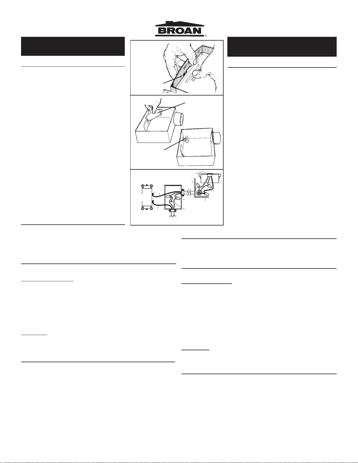
5. New installation in an existing ceiling or wall:
From above ceiling or behind wall, position housing
againststudorjoist.Traceoutlineofhousingonceiling
or wall material. (FIG. 6) Set housing aside and cut
opening. Place housing in opening such that its
BOTTOMEDGEISFLUSHWITHFINISHEDCEILING
OR WALL. 1/2" ceiling or wall material: Bend tabs
outward 900(use a screwdriver if desired) to rest on
topofceilingorwallmaterialandprovideextrastability.
Nail in place using four nails to ensure a solid, quiet
installation. (FIG. 7)
6. Install 3" round duct onto damper/duct connector. If
rigid ductwork is used, its seam should be positioned
at top of damper/duct connector. Tape the joint and
extendductingtoawallcaporroofcap.Makesurethe
damper operates freely. Ceiling or wall can now be
finished.
NOTE:Ifdamperdetachesfromductconnector,re-
insertitbysqueezingductconnectortop-to-bottom
while guiding posts on damper flap into holders in
ductconnector.Thehorizontalribshouldbeonthe
outside surface of damper flap and damper flap
should move freely inside of duct connector.
7. Replace themotor plateremovedin Step1. Inserttwo
motor plate tabs into slots in housing and then pivot
motor plate up until the third tab on plate snaps into
matching slot in housing. Make sure tabs hold motor
plate securely in place. Plug in motor. (FIG. 8)
8. Squeezegrillespringstogetherandinsertspringsinto
slots in motor plate. (FIG. 9) Push grille up against
ceiling or wall. (FIG. 10)
4. Escoja la posición de su ventilador. Para un mayor
rendimientouse el ductomáscorto posibleyun número
mínimodecodos. Parainstalacionesenlapared:Coloque
launidaddeformaquelatapadelhumidificadorsecierre
cuando la unidad se encuentre apagada.
5. Instalaciónnuevaantesdeponerlosacabadosdeltecho
ola pared:
ASEGÚRESE DE QUE LA CAJA SE ENCUENTRE AL
NIVEL DEL TECHO O LA PARED. Se proporcionan
pestañasranuradasparanivelarlacajacon1/2"deltecho
omaterial de la pared. Doble las pestañas hacia afuera
a90grados(useundesarmador siasilodesea)ycoloque
la caja de forma que las pestañas descansen contra el
extremo del fondo de los travesaños (o del frente de la
viga). Clave la caja al travesaño usando cuatro clavos
paraasegurar unainstalaciónsólida ysilenciosa.Insta-
lacionesentechos:laspestañasqueseencuentranen
laparteopuestadelacajapuedendoblarsehaciaafuera
hastadescansarencimade1/2"dematerialdetechopara
proveer estabilidad adicional. (FIG. 4)
5. Instalacióndereemplazo:
Coloquelacajadeformaqueestécentradaenlaabertura
existente.ASEGÚRESE DE QUE SE ENCUENTRE AL
NIVELDELTECHO OLAPARED.Despuésdehacerlas
conexiones eléctricas y del ducto de trabajo (Vea los
pasos4,5,y6),clavelacajaenellugarescogido.Coloque
losclavosenloslugaresmarcadosconunaflecha.(FIG.
5)
5. Instalaciónnuevaenuntecho oparedexistentes:
Desde arriba del techo o detrás de la pared, coloque la
cajacontralavigaotravesaño.Marqueloscontornosde
la caja en el material del techo o pared. (FIG. 6) Ponga
de lado la caja y corte la abertura. Coloque la caja en la
abertura de forma que EL EXTREMO DEL FONDO SE
ENCUENTREANIVELCONELTECHOACABADOOLA
PARED. 1/2 " de techo o material de pared: Doble las
pestañas90gradoshaciaelexterior(useundesarmador
siasílodesea)paradescansarencimadetechoomaterial
deparedyproporcionarasíunamayorestabilidad. Clave
en su lugar utilizando cuatro clavos para asegurar una
instalación sólida y silenciosa. (FIG. 7)
6. Instale ducto redondo de 3" en la conexión del humidifi-
cador/ ducto. Si se utiliza ducto de trabajo rígido, su
costuradeberacolocarseenlapartesuperiordelhumid-
ificador/ducto.Encintelauniónyextiendael ductohacia
latapadelaparedolatapadeltecho. Asegúresedeque
el humidificador funciona libremente. El techo o pared
pueden entonces ser acabados.
NOTA:Silaaletadelreguladordetirosedesprende
del conectador del conducto, vuelva a introducirla
comprimiendo el conectador de arriba a bajo al
tiempo que guía los postes de la aleta para
introducirlosenelsoportedelconectador.Elsaliente
horizontal debe quedar en la superficie externa de
la aleta del regulador de tiro, y ésta debe poder
moverse libremente dentro del conectador del
conducto.
7. Reemplacelaplacadelmotorquefueremovidaenelpaso
1. Inserte dos pestañas de la placa del motor dentro de
lasranurasenlacajayentoncesjaleusandolaplacadel
motor como pivote hasta que la tercera pata de la placa
encajaenlaranuracorrespondientedelacaja.Asegúrese
dequelaspestañassostienenlaplacadelmotordeforma
segura. Conecte el motor. (FIG. 8)
8. Presione conjuntamente los resortes de la parrilla e
insértelos dentro de las ranuras de la placa del motor.
(FIG.9) Empuje la parrilla contra el techo o pared.(FIG.
10)
FIG. 4 FIG. 5
12
4
2
7
3
68
5
10 11
BROANONEYEARLIMITEDWARRANTY
Broanwarrantstotheoriginalconsumerpurchaserofitsproductsthatsuchproductswillbe
freefromdefectsinmaterialsorworkmanshipforaperiodofoneyearfromthedateoforiginal
purchase.THEREARE NOOTHER WARRANTIES,EXPRESS ORIMPLIED, INCLUD-
ING, BUT NOT LIMITED TO, IMPLIED WARRANTIES OF MERCHANTABILITY OR
FITNESS FOR A PARTICULAR PURPOSE.
Duringthisone-yearperiod,Broanwill,atitsoption,repairorreplace,withoutcharge,any
productor partwhich is foundto bedefective under normaluse andservice.
THIS WARRANTY DOES NOT EXTEND TO FLUORESCENT LAMP STARTERS AND
TUBES. This warranty does not cover (a) normal maintenance and service or (b) any
products or parts which have been subject to misuse, negligence, accident, improper
maintenance or repair (other than by Broan), faulty installation or installation contrary to
recommendedinstallationinstructions.
Theduration of any implied warranty is limited to the one-year period as specified for the
expresswarranty.Somestatesdonotallowlimitationonhowlonganimpliedwarrantylasts,
sothe above limitation may not apply to you.
BROAN’SOBLIGATIONTOREPAIRORREPLACE,ATBROAN’SOPTION,SHALLBE
THE PURCHASER’S SOLE AND EXCLUSIVE REMEDY UNDER THIS WARRANTY.
BROANSHALL NOT BE LIABLE FOR INCIDENTAL,CONSEQUENTIALOR SPECIAL
DAMAGES ARISING OUT OF OR IN CONNECTION WITH PRODUCT USE OR
PERFORMANCE. Some states do not allow the exclusion or limitation of incidental or
consequentialdamages,sotheabovelimitationorexclusionmaynotapplytoyou.
Thiswarrantygivesyouspecificlegalrights,andyoumayalsohaveotherrights,whichvary
from state to state. This warranty supersedes all prior warranties.
To qualify for warranty service, you must (a) notify Broan at the address stated below or
telephone:1-800-637-1453,(b)givethemodelnumberandpartidentificationand(c)describe
thenature of any defectinthe product or part. Atthe time of requesting warrantyservice,
youmustpresentevidenceoftheoriginalpurchasedate.
Broan-NuTone LLC, 926 West State Street, Hartford, WI 53027
61574 99041024AA
SERVICEPARTS KEY PARTNUMBER NO. PIEZASDESERVICIO
NO. NO.PIEZ CÓDIGO
Grille Assembly (Includes Key Nos 1 97011723 1 Ensambledelaparrilla
1 & 2) (Incluye código Nos. 1 y 2)
GrilleSpring(2Required) 2 99140187 2 Resorte de la parrilla
(Son necesarios 2)
Motor(Model670) 3 99080254 3 Motor(Modelo670)
Motor(Model671) 99080255 Motor(Modelo671)
Motor(Model688) 97012041 Motor(Modelo688)
Motor(Model689) 97012042 Motor(Modelo689)
MotorPlate 4 98006791 4 Placa del motor
BlowerWheel (Model670& 671) 5 99110655 5 Rotor de soplo (Modelo 670 y 671)
BlowerWheel (Model688& 689) 6 99111002 6 Rotor de soplo (Modelo 688 y 689)
Nut#6-32(2Required) 7 99260428 7 Tuerca No. 6-32 (Son necesarias 2)
Damper/DuctConnector 8 97016377 8 Conexiónhumidificador/Ducto
(Models 670, 671, 688, 689) (Modelos 670, 671, 688 y 689)
Damper/DuctConnector 9 97015577 9 Conexiónhumidificador/Ducto
(Model1667HMTL)) (Modelos1667HMTL)
Receptacle 10 99271252 10 Receptáculo
WiringCover 11 98006773 11 Cubiertadelalambrado
HousingAssembly 12 97008319 12 Ensamble de la caja
Screw,#8-18 13 99150478 13 Tornillo,#8-18
Always order replacement parts by "PART NUMBER" - not by "KEY NO."
Siempre encargue piezas de reemplazo por "NO. PIEZA" y no por "NO. CÓDIGO"
PIEZAS DE
SERVICIO
SERVICE
PARTS
FIG. 6 FIG. 7
FIG. 8 FIG. 9
FIG. 10
TABS
PESTAÑAS
¬¬
¬¬
¬
¬¬
¬¬
¬
¬¬
¬¬
¬
1
9
13
GARANTÍABROANLIMITADAPORUNAÑO
Broangarantizaalconsumidorcompradororiginaldesusproductosquedichosproductos
carecerándedefectosenmaterialesoenmanodeobraporunperíododeunañoapartirde
lafechaoriginaldecompra.NOEXISTENOTRASGARANTÍAS,EXPRESASOIMPLÍCI-
TAS,INCLUYENDO,PERO NO LIMITADAS A, GARANTÍAS IMPLÍCITAS DE COMER-
CIALIZACIÓN O APTITUD PARA UN PROPÓSITO PARTICULAR.
Duranteelperíododeunaño,yasupropiocriterio, Broanrepararáoreemplazará,sincosto
algunocualquierproductoopiezaqueseencuentredefectuosabajocondicionesnormalesde
servicio y uso.
ESTA GARANTÍA NO SE APLICA A TUBOS Y ARRANCADORES DE LÁMPARAS
FLUORESCENTES. Estagarantía no cubre (a) mantenimiento y servicionormaleso (b)
cualquierproductoopiezasquehayansidoutilizadasdeformaerrónea,negligente,quehayan
causadounaccidente,oquehayansidomantenidasoreparadasinapropiadamente(porotras
compañías que no sea Broan), instalación defectuosa, o instalación contraria a las
instruccionesdeinstalaciónrecomendadas.
Laduracióndecualquiergarantíaimplícitaselimitaaunperíododeunañocomoseespecifica
enlagarantíaexpresa. Algunos estadosno permitenlimitaciones encuanto altiempo de
expiracióndeuna garantía implícita, por lo que la limitacíon antes mencionada puede no
aplicarseausted.
LAOBLIGACIÓNDEBROANDEREPARAROREEMPLAZAR,SIGUIENDOELCRITERIO
DEBROAN,DEBERÁSERELÚNICOYEXCLUSIVORECURSOLEGALDELCOMPRA-
DOR BAJO ESTA GARANTÍA. BROAN NO SERÁ RESPONSABLE POR DAÑOS
ACCIDENTALES,CONSIGUIENTES, OPOR DAÑOS ESPECIALESSURGIDOS O EN
CONEXIÓNCONEL USOOEL RENDIMIENTODELPRODUCTO. Algunos estadosno
permitenlaexclusiónolimitacióndedañosaccidentalesoconsiguientes,porloquelalimitación
antesmencionadapuedenoaplicarseausted.Estagarantíaleproporcionaderechoslegales
específicos, y usted puede también tener otros derechos, los cuales varían de estado a
estado. Estagarantíareemplazatodaslasgarantíasanteriores.Paracalificarenelservicio
degarantía,usteddebe(a)notificaraBroanaldomicilioquesemencionaabajooaltelefono:
1-800-637-1453,(b)darelnúmerodelmodeloylaidentificacióndelapiezay(c)describirla
naturalezadecualquierdefectoenelproductoopieza. Enelmomentodesolicitarservicio
cubiertoporlagarantía,usteddebepresentarevidenciadelafechaoriginaldecompra.
Broan-NuTone LLC, 926 West State Street, Hartford, WI 53027 U.S.A.