Brother WD-200 SERIES User manual

User's Guide
WD-200 Series
This guide contains precautions
and operation methods for use
with this product.
Read the whole guide before using
your product and keep it for later
reference.
Troubleshooting
If you have any problems
with this product, to find a
solution see
Page 35
User's Guide WD-200
Version 0
UK ENG

2
1. Introduction
We use the following symbols and conventions throughout this
User's Guide:
Symbols and conventions used in
this document
[Important]
Explains precautions that must be observed
when using this product.
[Note]
Provides supplementary information about
using this product.

3
Introduction
1.Introduction ......................................................................... 2
Symbols and conventions used in this document ............. 2
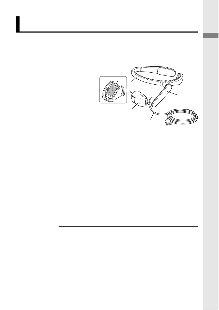
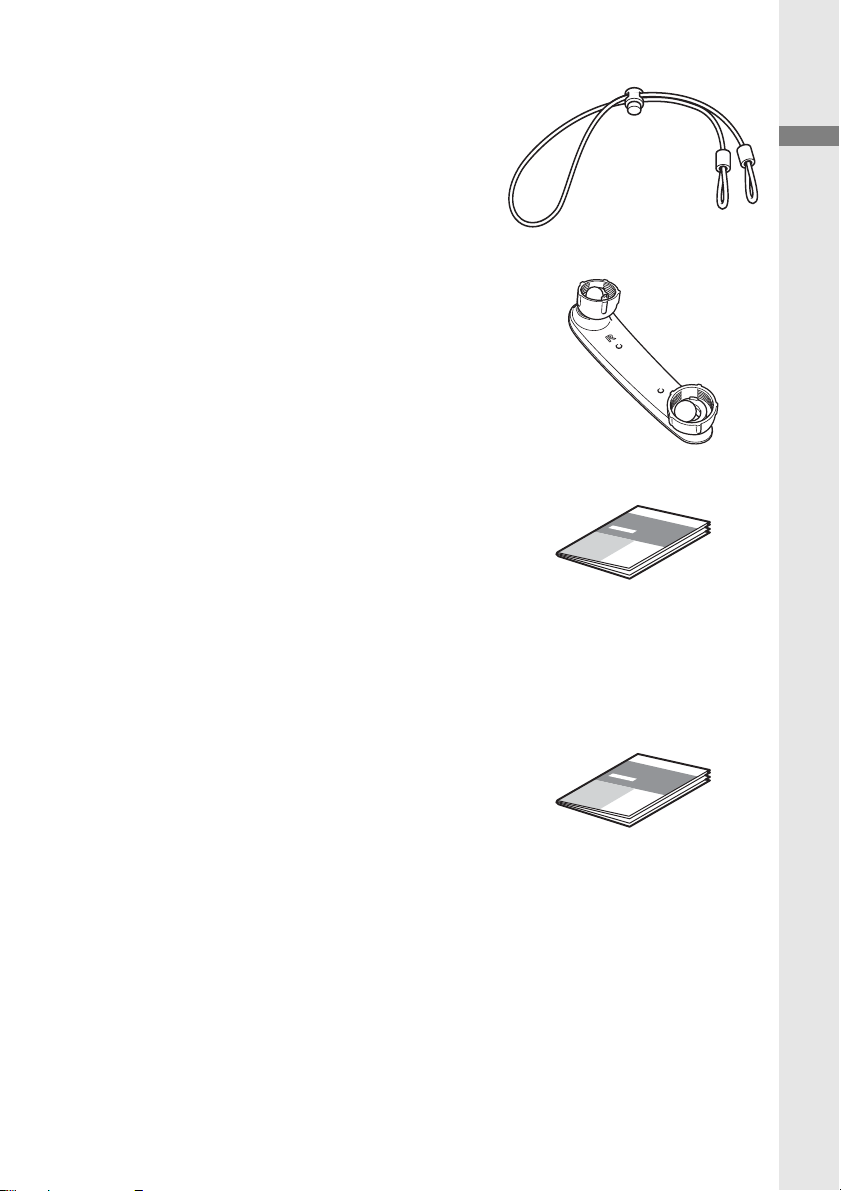
Checking package contents.............................................. 5
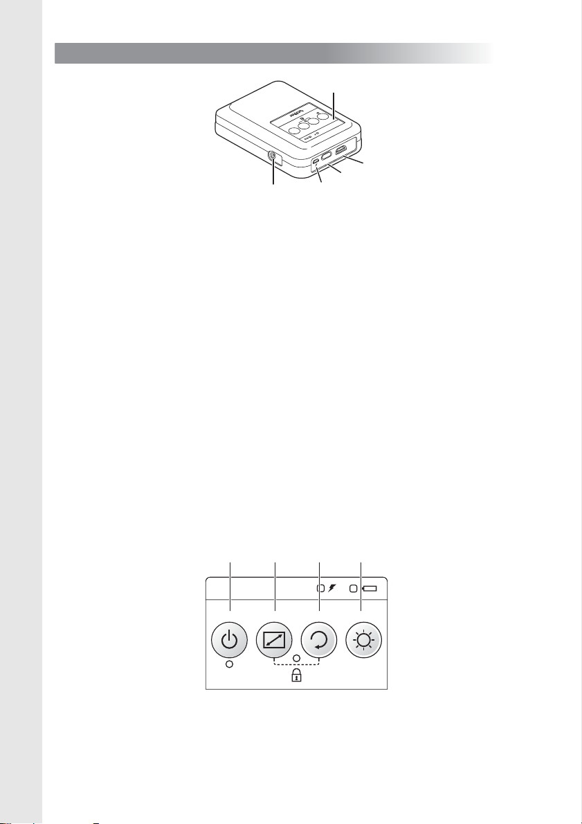
Names and functions of main parts ..................................8
2.Before you start ................................................................ 14
Assembly ........................................................................ 14
Mounting ......................................................................... 16
3.Display .............................................................................. 17
Turn the power on........................................................... 17
Adjust the head display to suit the application ................17
Adjust the focal length..................................................... 18
4.Settings............................................................................. 19
Adjust brightness ............................................................ 19
Lock the control panel.....................................................19
Enlarge the centre of the screen.....................................20
Rotate the image............................................................. 20
Replace the pads ............................................................21
Attach the rear band .......................................................22
Replace with the flexible arm for right eye ...................... 24
Replace the mirror unit.................................................... 28
Power supply .................................................................. 30
Use external batteries ..........................................31
Set Power Saving Mode.......................................32
5.Maintenance ..................................................................... 33
Clean the mirror unit ....................................................... 33
Clean the head band....................................................... 34
Clean the control box ......................................................34
Contents

4
6.Troubleshooting................................................................ 35
Appendix ............................................................................. 42
Li-ion rechargeable batteries .......................................... 42
Product specification ...................................................... 44
Consumables and optional accessories ......................... 46
Requesting repairs ......................................................... 47

5
Introduction
Introduction
Before using the AiRScouter, check that package contents
are complete.
Head Display kit
The head display,
flexible arm, head
band, and Pad (M size)
are pre-assembled.
aHead Display
Displays images sent
from the control box.
bFull mirror unit
Projects images from the head display.
cFlexible Arm
Allows you to adjust the head display to the position and
angle you want.
dHead Band
Supports the product on your head.
eVideo Input Cable
Allows you to connect the control box to the head
display.
Checking package contents
[Note] If the head band feels too loose, use the rear
band to support it.
a
c
bd
e

6
Control Box
Sends images from external
devices to the head display.
It also allows you to adjust the
brightness, and to enlarge and
rotate the image.
AC adapter
Supplies power to the control box,
and is also used to charge the
internal battery.
The plug may differ by country.
Li-ion (lithium ion)
rechargeable battery
Before using the AiRScouter, fit
the battery into the control box
and use the AC adapter provided
to charge it.
Cable Clip
Use this clip to attach the cable to
your clothing, to keep it out of the
way. Attach the string of the cable
clip to the cable, as shown on the
right.

7
Introduction
Rear Band
Attach this to the head band as
necessary to prevent the head
band from falling off, and to help
tighten the headset.
Flexible arm for right eye
Replace the flexible arm for left
eye with the flexible arm for right
eye if viewing the head display
with your right eye. The letter "R" is
printed on the flexible arm for right
eye.
User's Guide (this document)
Explains the basic functions and
operation of the AiRScouter, as
well as other content, such as
maintenance methods.
Also, use it to check what to do if a
problem occurs (for example, loss
of video output).
Product Safety Guide
Explains precautions for use with
this product.
Read this Guide first.

8
Head Display
aFocal length adjusting dial
Adjusts the focal length of the displayed image. The
adjustment range of the focal length is between 30 cm
and 5 m.
bFull mirror unit
Projects images from the head display onto the eye.
It has a lens cover attached on the inside to protect the
lens inside the head display.
cVideo Input Cable
Connects the control box to the head display.
dEyeglass protection sheet
If you use the AiRScouter with glasses on, this sheet
prevents force being exerted on the head display and
possible damage to the glasses if a lens is touched.
Names and functions of main parts
c
a
b
d

9
Introduction
Harness
aHead Band
Hold this part when placing the AiRScouter on your
head.
bForehead Pad
Prevents the head band from slipping down the
forehead.
cCable Fix Slot
Holds the head display cable along the head band.
dRear Band attachment
Allows you to attach the rear band, to prevent the head
band from falling off, and to help tighten it onto the head.
eFlexible Arm
Allows you to freely adjust the position and angle of the
head display relative to the eye.
fDial
Adjusts the stiffness of the flexible arm ball joint.
b
c
d
e
f
a

10
Control Box
aControl Panel
Includes control buttons, status LEDs, and a battery level
indicator.
bAC adapter connecting socket
Allows you to connect the AC adapter to power the
control box and charge the internal battery.
cHDMI connecting port
Allows you to connect HDMI-compatible devices.
dHead Display connecting port
Allows you to connect the head display to the control
box.
eUSB micro-B port for external battery
Allows you to connect a third-party USB battery. This
port cannot be used to charge the internal battery.
Control Panel buttons
a
b
c
d
e
a b c d

11
Introduction
aPower button
Press this button to turn the AiRScouter on. Press and
hold this button for two seconds to turn the AiRScouter
off.
The power automatically turns OFF if there is no input
from a video source for one minute or more.
bMode button
Press this button to select the zoom mode. For more
information, see page 20.
cRotate button
Press this button to rotate the image by 180°. Press and
hold it for two seconds to flip the image horizontally.
dBrightness button
Press this button to select one of five brightness levels.
Control Panel Status LEDs
aDisplay LED (green)
Lights while the AiRScouter is on and an image is being
projected on the display.
bKey Lock LED (orange)
Lights when button operation on the control box is
locked. For more information, see page 19.
cInternal battery LED (orange)
Lights during battery charging.
dExternal power LED (orange)
Lights when power is supplied from the AC adapter, or
from an external battery (third-party USB battery).
ab
cd

12
LED indications
lit flashing off
aDisplay LED (green)
bKey Lock LED (orange)
cInternal battery LED (orange)
State Name Explanation
Display ON
The AiRScouter receives
video, which appears on the
head display, from an external
device.
(Slowly) Operating The control box is operating.
(Quickly) No input
The AiRScouter receives no
video signal from an external
device.
Power OFF
The AiRScouter is turned off.
To turn it on, press the power
button.
State Name Explanation
Key Lock ON Button operation on the
control box is locked.
Key Lock
OFF
Button operation on the
control box is unlocked.
State Name Explanation
Battery level
high
The charge level of the
internal battery is full.
(Slowly) Battery level
medium
The charge level of the
internal battery is close to
half-full.
(Quickly) Battery level
low
The charge level of the
internal battery is low.
No battery
The charge level of the internal
battery is close to zero.

13
Introduction
dExternal power LED (orange)
(For the AC adapter)
dExternal power LED (orange)
(For the external battery)
State Name Explanation
Working The AiRScouter is using the
AC adapter.
(Slowly) Charging
The internal battery is charging.
(Quickly) Charging
error
An error occurred while the
internal battery was charging.
Full charge The internal battery is fully
charged.
State Name Explanation
Working The AiRScouter is using an
external battery.
(Quickly) Connection
error
An error occurred while the
external battery was supplying
power.
No battery
The charge level of the
external battery is low.
If the internal battery is
charged, the AiRScouter will
use it (the internal battery LED
lights).

14
2. Before you start
Assemble the AiRScouter and make connections according to
the following procedure:
Feed the cable along the cable fix slots of the flexible arm
and the head band, and then fasten it firmly.
Insert the internal battery into the control box:
a) Remove the cover
screws from the control
box, and then insert the
Li-ion rechargeable
battery.
b) After inserting the
battery, close the control
box cover and tighten
the screws.
Assembly
[Important]
Make sure you insert the battery in the correct way.
Inserting the battery incorrectly will damage the
AiRScouter.
[Note]
If you are not using the internal battery, connect the
AC adapter to the control box.
1
2

15
Before you start
Connect the supplied AC adapter to the control box to
fully charge the internal battery.
Connect the video input cable of the head display to the
control box.
Connect the video input cable or an HDMI connecting
port to the control box.
[Note]
Before you use the battery for the first time,
charge it fully. For more information, see page 42.
[Note]
The only supported resolution for input
devices is 1280 × 720 p. If a device with a
different resolution is connected, the screen
may not display correctly.
Use HDMI cables of up to 2 m.
3
4
5

16
Fit the head band to the
head.
If you wear glasses
• If the arms of the glasses are straight, they may touch the head
band. Such contact may cause excess pressure on the ears.
• If the ends of the arms of the glasses are curved, they will not
touch the head band. Glasses with curved arm ends allow for a
more comfortable fit.
Use the cable clip to attach the cable to your clothing.
Mounting
[Note]
If the pads do not fit, replace them with pads
of the right size. (See page 21)
If the head band feels loose, use the rear band.
(See page 22)
If you wear glasses with
straight arms
If you wear glasses with
curved arm ends
1
2

17
Display
3. Display
Press the power button to
turn the AiRScouter on (the
LED below the power
button lights in green).
Adjust the flexible arm to put
the head display in a
position that is easy to view.
Turn the power on
Adjust the head display to suit the
application
[Note]
If the Ball Joint becomes loose after repeated
adjustments of the head display position, turn
the dial of the flexible arm to tighten it.
If it is not possible to bring the image into the
field of view just by adjusting the flexible arm,
adjust the position of the head band.

18
Adjusting the Head Display to suit the application
Display the image at your preferred position, to match
your working posture. If the mirror is positioned outside
the range that can be reached by eye movement, it
may appear that the image is missing.
• If you want to keep the image
always in the field of view, place
the mirror in front of the eye.
•
If you want to check the image only
when necessary, place the mirror
at the edge of the field of view.
This way, you can look at the
image only when necessary, while
retaining the normal field of view.
Turn the focal length adjusting dial to adjust the focal
length between 30 cm and 5 m.
Adjust the focal length

19
Settings
4. Settings
Press the brightness button on the control box to adjust
the brightness of the image.
To lock the panel (the key lock function), preventing
unintentional operation, press the mode button and the rotate
button on the control box at the same time.
The key lock LED is lit in orange when the key lock is active.
Adjust brightness
Lock the control panel
[Note]
To unlock the key lock, press the mode button
and the rotate button at the same time again.

20
You can enlarge the centre of the screen by using Central
Enlarge Mode.
Each time you press the
mode button, the display
toggles between enlargement
of the centre and normal
display of the whole image.
You can rotate the image by 180° or flip it horizontally.
• To rotate the image by 180°,
press the rotate button.
• To flip the image horizontally,
press and hold the rotate
button for two seconds.
Enlarge the centre of the screen
Rotate the image
Table of contents