manuals.online logo
Brands
  1. Home
  2. •
  3. Brands
  4. •
  5. Brunton
  6. •
  7. Compass
  8. •
  9. Brunton GeoTransit User manual

Brunton GeoTransit User manual

Other manuals for GeoTransit

1

Other Brunton Compass manuals

Brunton ECLIPSE 8096 User manual

Brunton

Brunton ECLIPSE 8096 User manual

Brunton 58CE Manual

Brunton

Brunton 58CE Manual

Brunton OmniSlope User manual

Brunton

Brunton OmniSlope User manual

Brunton NOMAD V2 PRO User manual

Brunton

Brunton NOMAD V2 PRO User manual

Brunton Eclipse 8097 User manual

Brunton

Brunton Eclipse 8097 User manual

Brunton GEO LITE TRANSIT F-5030 User manual

Brunton

Brunton GEO LITE TRANSIT F-5030 User manual

Brunton Nomad V2 User manual

Brunton

Brunton Nomad V2 User manual

Brunton 15TDCL User manual

Brunton

Brunton 15TDCL User manual

Brunton 16B Braille User manual

Brunton

Brunton 16B Braille User manual

Brunton Nomad 2004 User manual

Brunton

Brunton Nomad 2004 User manual

Brunton Omni-Sight User manual

Brunton

Brunton Omni-Sight User manual

Brunton Classic Compass User manual

Brunton

Brunton Classic Compass User manual

Brunton TruArc User manual

Brunton

Brunton TruArc User manual

Brunton 85R Manual

Brunton

Brunton 85R Manual

Brunton OSSl User manual

Brunton

Brunton OSSl User manual

Brunton Outback User manual

Brunton

Brunton Outback User manual

Brunton 9075 User manual

Brunton

Brunton 9075 User manual

Brunton Nomad V2 Pro User manual

Brunton

Brunton Nomad V2 Pro User manual

Brunton 9020 User manual

Brunton

Brunton 9020 User manual

Brunton 7DNL User manual

Brunton

Brunton 7DNL User manual

Brunton Transit User manual

Brunton

Brunton Transit User manual

Brunton ECLIPSE 8099 User manual

Brunton

Brunton ECLIPSE 8099 User manual

Brunton GeoTransit User manual

Brunton

Brunton GeoTransit User manual

Brunton 54lu User manual

Brunton

Brunton 54lu User manual

Popular Compass manuals by other brands

Silva EXPLORER 203 quick start guide

Silva

Silva EXPLORER 203 quick start guide

Quechua C Quechua 400 manual

Quechua

Quechua C Quechua 400 manual

Advanced Navigation GNSS Compass Reference manual

Advanced Navigation

Advanced Navigation GNSS Compass Reference manual

Bushnell 70-0101 instruction manual

Bushnell

Bushnell 70-0101 instruction manual

BW SENSING LEC315M Technical manual

BW SENSING

BW SENSING LEC315M Technical manual

True North Revolution user guide

True North

True North Revolution user guide

Furuno Sc 50 Operator's manual

Furuno

Furuno Sc 50 Operator's manual

Nexus NX2 Compass Installation and operation manual

Nexus

Nexus NX2 Compass Installation and operation manual

Anschutz 133-811.NG001 Operator's and service manual

Anschutz

Anschutz 133-811.NG001 Operator's and service manual

SG Brown Meridian System manual

SG Brown

SG Brown Meridian System manual

Riviera ASTRA 4 user manual

Riviera

Riviera ASTRA 4 user manual

Nexus NX Compass Installation and operation manual

Nexus

Nexus NX Compass Installation and operation manual

Hama Digital Compas operating instructions

Hama

Hama Digital Compas operating instructions

Oregon Scientific RA202 user manual

Oregon Scientific

Oregon Scientific RA202 user manual

Sherpa BW2 manual

Sherpa

Sherpa BW2 manual

Technoline EA 3050 manual

Technoline

Technoline EA 3050 manual

ComNav Vector G2 Installation and operation manual

ComNav

ComNav Vector G2 Installation and operation manual

Vetus EC Operation manual and installation instructions

Vetus

Vetus EC Operation manual and installation instructions

manuals.online logo
manuals.online logoBrands
  • About & Mission
  • Contact us
  • Privacy Policy
  • Terms and Conditions

Copyright 2025 Manuals.Online. All Rights Reserved.

G E O T R A N S I T
OPERATORS MANUAL
1  Orientation ........................................................................ Page(s): 1
2  Magnetic Declination ....................................................................... 5
3  Azimuth Measurement .................................................................... 7
4 -- Inclination & Percent Grade Measurement ............................... 11
5  Strike & Dip Measurement ............................................................ 14
6  Trend & Plunge Measurement ..................................................... 15
7  GEO Transit & Topographic Map Use ......................................... 16
8  Additional Measurements ............................................................ 18
9  Prospecting ..................................................................................... 19
10  Reference Material ....................................................................... 25
11  Specifications ................................................................................ 26
12  Service ............................................................................................ 26
i
Copyright BRUNTON, 2001
Printed in U.S.A.
form 11-GEO rev. 0109
Owners Purchase Record
Model _______________________________________________________
Date of Purchase ______________________________________________
Dealer Purchased From: _________________________________________
_____________________________________________________________
Serial #:
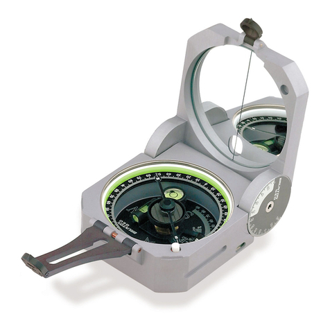
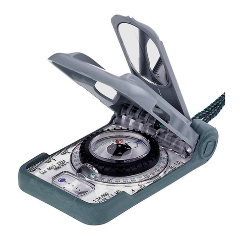
Congratulations on your purchase of the finest pocket transit instrument in the world.
The Brunton GEO Transit is not just a compass. It combines a surveyors compass, pris-
matic compass, two inclinometers, hand level and a plumb into a single instrument.
Even though the GEO Transit is made rugged and durable to withstand the rigor associ-
ated with outdoor use, care must be taken to assure long-life of your instrument. Avoid
impacts, dropping, extreme temperatures and store the Brunton GEO Transit in its case.
Orientation provides a description of important
pocket transit parts. A detailed description of its
operation is provided throughout the manual.
Opening The GEO Transit
Position the GEO Transit so that the flat cover
faces up with the small window positioned away
from you. Unlatch the cover from the base.
(Fig 1)
1.1 Round Level (Fig 2)
For accurate azimuth measurement, dip direction and trend measurements, center the bubble
in the round level.
1.2 Needle (Fig 2)
The needle is attached to a rare earth magnet which is induction damped, allowing the needle
to seek magnetic north and come to a complete rest in a minimum amount of time.
1.3 Graduated Circle (Fig 2)
In combination with the needle, the 1° graduated circle allows for azimuth readings that are
accurate to 1/2 degree.
1.4 Long Level (Fig 2)
The long level is for inclination measurement. For accurate inclination measurement, center
the bubble in the long level using the vernier adjustment (section 1.14).
1.5 Rare Earth Magnet (Fig 2)
Brunton has incorporated a cast NdFeB, rare-earth magnet which seeks magnetic north very
quickly and allows for faster needle settling.
1.6 Zero Pin (Fig 2)
The zero pin a pointer used for magnetic declination adjustment. If no adjustment is
necessary, the pin should point at 0° on the azimuth ring.
1.7 Needle Release Mechanism -- 2-Positions (Fig 2)
Unlocked: When needle locking adjustment (section 1.15) is unlocked the needle swings
freely, even when needle release mechanism is pressed.
Locked: When needle locking adjustment is in the locked position the needle is locked in
place until the needle release mechanism is pressed. (Suggested for Storage)
1 -- Orientation
21
1.3 1.4
1.5
1.2
1.1
1.8 1.7
1.6
1.10 1.9
Figure 1
Figure 2
Flat Cover
Small Window
1.13 Large Sight w/ Peep Sight (Fig 3)
The large sight and the attached buckhorn style peep sight are used for precise azimuth and
inclination measurement.
1.14 Vernier Adjustment (Fig 3)
The vernier adjustment rotates the vernier and long level for inclination measurements.
1.15 Needle Locking Adjustment -- 2-Positions (Fig 3)
Adjust the needle locking lever to lock and unlock the needle.
1.16 Side/Bottom Long Levels (Fig 3)
When it is not possible to view the round level, use the side/bottom, long levels to level the
GEO transit for azimuth and inclination measurement .
1.17 Hinge Inclinometer (Fig 3)
Measure inclination using the lid and at least one of the bubble levels.
Storage
For storage, Brunton recommends locking the
needle adjustment lever (1.15) and placing the
GEO transit in its case, with the base against the
closing snap. (Fig 4)
Direct Reading
Why are EAST & WEST switched?
The GEO Transit is a direct reading compass.
Read azimuth directly where the needle points
on the graduated circle.
With the large sight toward the object, read azimuth directly where the north end of the nee-
dle points (N tip). (Fig 5)
1.8 Vernier (Fig 2)
The vernier is used for inclination measurements with an accuracy to 30 minutes.
1.9 Mirror (Fig 2)
The mirror and mirror center line are used for accurate azimuth and inclination measurements.
1.10 Small Sight (Fig 2)
Attached to the cover, the small buckhorn style sight is used for precise bearing and inclina-
tion sighting.
1.11 Ball & Socket Tripod Mount (Fig 3)
Use the slots on both sides of the body for mounting the GEO to the optional Brunton ball &
socket mount, which in turn attaches to an optional Brunton tripod, or monopod.
1.12 Magnetic Declination Adjustment Screw (Fig 3)
Adjust the GEO Transit for magnetic declination, by turning the declination adjustment screw
using a flat-head screw driver.
43
Figure 4
Base
Figure 3
1.11
1.13
1.12
1.15
1.16
1.14
1.17
Snap
With the small sight toward the object, read azimuth directly where the south end of the nee-
dle points (S tip). (Fig 6)
See section 4 for detailed explanation of sighting an azimuth.
The Earth is completely surrounded by a magnetic field, and an unobstructed magnetized
object will orient itself with the earths magnetic north and south poles. Magnetic declination
(variation) is the difference between true, geographic north (North Pole) and magnetic north
(in northern Canada), with respect to your position. It is important to note magnetic declina-
tion at your position, because magnetic declination varies and fluctuate slowly at different
rates, around the world.
The isogonic chart (Fig 7) shows North America, only. Use the isogonic chart, a current
United States Geological Survey (USGS), Bureau of Land Management (BLM), another
map, or a computer program to determine magnetic declination at your position.
Declination can be east, west or 0°, from your current position. At 0° declination, true north
and magnetic north are aligned.
Example: If magnetic declination at your position is 15° east, then mag-
netic north is 15° east of true, geographic north. Figure 8 displays true
geographic north and magnetic north, as indicated in the legends of
USGS and BLM maps.
Most maps use true north as a reference. When adjustment for magnet-
ic declination is complete, azimuth readings will be with respect to true
north, same as the map.
True North
Magnetic North
15oE
Your Position
Figure 8
Figure 7
West Declination
East Declination
65
Object
Large Sight
N Tip
Figure 5
Small Sight
S Tip
Object
Figure 6
2 -- Magnetic Declination
2. Rotate the needle locking adjustment lever clock-wise.
(Fig 10)
Now the needle swings freely, even when needle release
mechanism is pressed.
3.1.b Needle Locked (Locked)
1. Position GEO transit so that the base faces you with the
needle locking adjustment on top. (Fig 10)
2. Rotate the needle locking adjustment lever counter
clock-wise.
The needle remains locked until the needle release mechanism is pressed. When the needle
settles, let up on the release mechanism to lock azimuth measurement in place.
3.2 Azimuth Using a Tripod or Monopod
For highest accuracy, mount the GEO transit on a Brunton non-magnetic tripod using the
Brunton ball and socket head.
1. Adjust GEO transit for magnetic declination.
!See section 2, Magnetic Declination, for help.
2. Mount transit to the ball and socket head.
3. Open the cover and large sight until they both
extend in a straight line. (Fig 11)
4. Flip small sight and peep sight up.
5. Rotate transit until large sight points at object.
6. Level the transit by centering bubble in round level.
7. Sight azimuth by aligning
peep-sights with object.
(Fig 12)
Using the magnetic declination adjustment (1.12, pg. 3), rotate the graduated circle to adjust
for declination. Begin with the zero pin at 0°. For East declination, rotate graduated circle
clockwise from the zero pin. (Fig 9A) For West declination, rotate graduated circle count-
er-clockwise. (Fig 9B) If magnetic declination is 0°, no adjustment is necessary. (Fig 9C)
Azimuth is a term used for direction. Azimuth is normally measured clockwise, in degrees with
true north being 0°. Bearing is a term often used when measuring with a quadrant type instru-
ment. From this point forward, description of pocket transit use will involve the 0° through 360°
graduated circle, and with the assumption the GEO transit is adjusted for magnetic declination.
Example of Azimuth: If a mountain is directly east of your position, the azimuth from your posi-
tion to the mountain is 90°. If the mountain is directly south, it would be at 180°.
Warning: The magnetic needle is highly sensitive. When sighting an azimuth, keep the GEO
transit away from magnetic materials, such as watches, belt buckles, rings, knives, etc.
3.1 Needle Locking Adjustment
Before measuring an azimuth a decision must be made to have the needle swing freely, or be
locked until the needle release mechanism is pressed.
3.1.a Needle Swings Freely (Unlocked)
1. Position the GEO so that the base faces you and the needle locking adjustment is on top.
Figure 11
87
Zero Pin Zero Pin Zero Pin
Figure 9A Figure 9B Figure 9C
15° East
Declination
15°West
Declination
0°
Declination
Figure 10
Figure 12
Object
Adjustment
3 -- Azimuth Measurement
8. Read azimuth where the "N" end of the needle points at
graduated circle. (Fig 13)
3.3 Azimuth Measurement Waist-Level
This method is often used when object is above or below
the observer.
3.3.a Using "N" End of Needle
Use this method when the object lies as much as 45°
above, or 15° below the observer.
1. Hold transit waist high and in your left hand.
2. Open cover toward your body . (Fig 14)
3. Open large sight, until perpendicular to the body.
(Fig 14)
4. Press left forearm against
your waist and steady with
right hand.
5. Level compass using round
bubble level.
6. In the mirrors reflection, bisect the object with the mirror center
line. (Fig 15)
!Check that the bubble is centered in the round level.
7. Read azimuth where the "N" end of needle points at the graduated
circle.
If object is more than 45° above you, open mirror further toward your
body, and adjust large sight so that it leans over the bottom case.
3.3.b Using "S" End of Needle
Use this method when object is more than 15° below the observer.
1. Hold transit waist high and in your left hand.
2. Open cover away from your body. (Fig 16)
3. Open large sight until it leans over the body.
4. Press left forearm against your waist and steady with
right hand.
5. Look just over the large sight, and at the object
through window opening on mirror. (Fig 16)
!Adjust mirror and large sight so that the image of
the large peep sight are bisected by the mirror
center line.
6. Level compass using round bubble level.
7. Read azimuth where the "S" end of needle points at
the graduated circle. (Fig 17)
3.4 Using as a Prismatic Compass
Occasionally, objects may interfere with sighting using meth-
ods previously mentioned, or users may encounter circum-
stances which require the GEO be held at eye-level to sight
an object. If this is the case, follow the procedures below.
1. Open cover away from your body to approximately 45°, and open small sight. (Fig 18)
2. Lift large sight until perpendicular to the transit body, or leans slightly away from the base.
3. Hold instrument at eye-level, with large sight toward you.
4. Align large sight and small sight on top of the cover with
object.
!OR - Sight object through the lower portion of large sight
and the window in the mirror.
5. Level round bubble level using the reflection of the mirror.
6. Read azimuth in the reflection of the mirror where the "S"
end of needle points at the graduated circle.
Figure 18
TO EYE
Figure 17
109
Figure 15
Figure 16
Figure 13
Figure 14
TO EYE
2. Find minutes by determining whether the 30 or 60 minute line is closest to a degree
marking. See arrows in figure 21. A Loupe or magnifier may be required.
Since the 30 minute line is closest, the total angle is 26° + 30 (26° 30 or 26.50°)
4.1.b -- percent grade
Use the percent grade scale above the vernier.
1. Read nearest percent grade at the verniers
center line -- 50%, circled. (Fig 22)
Another method is to calculate the percent grade
using the angle of inclination and the equation:
Percent Grade = [ tan(
"#
) x 100 ]
Measure the angle of inclination,
"
= 26.5°. Then, calculate the tangent of 26.5° using a cal-
culator. Finally, move the decimal two places to the right (multiply by 100).
Example: Tan( 26.5°) = .499 = 49.9% Grade
4.2 Inclination Using Prismatic Compass
The GEO transit can also measure angles of inclination without a tripod.
1. Position cover to approximately 45°.
2. Open large sight and flip its peep sight to 90° from
the large sight. (Fig 23)
3. With large sight pointing toward you, position transit
at eye-level with cover open to the right. (Fig 23)
4. Sight object behind transit, aligning small sight,
window and peep sight with object.
5. In the mirror, adjust vernier until bubble is centered in
the long level .
6. Read inclination at verniers center line.
The Brunton GEO Transit is capable of measuring vertical angles with an accuracy better
than 1°, with readings to 10 minutes. Also, it
displays percent grade, without calculation.
The bottom scale is incremented from 0° to 90°
and is used for vertical inclination. The scale on
the vernier is also used for vertical (inclination)
measurement, but it is incremented from 0 to 60
minutes. (Fig 19) Closer to the center, the sec-
ond scale increments from 0% to 100%. This
scale is the percent grade scale.
4.1 Inclination and Percent Grade Using Tripod or Monopod
Use a tri/monopod for increased inclination accuracy.
1. With GEO transit attached to the tripod tilt the ball
and socket mount 90°. (Fig 20)
!Transit should be on its side.
2. Lock into position using the clamp screw.
3. Align sights with object behind transit. (Fig 20)
4. Adjust vernier until bubble is centered in long level.
5. Read inclination at verniers center line from the
degree scale -- 26° to 27°, circled. (Fig 21)
4.1.a -- inclination to the nearest 30 minutes
When 30 minute accuracy is required, use the
vernier scale (0 -- 60 minutes with 10 minute incre-
ments).
1. Read inclination at verniers center line --
26° + __  , circled. (Fig 21)
1211
Figure 19
Figure 21
Figure 22
Figure 20
Figure 23
TO EYE
4 -- Inclination & Percent Grade Measurement
Strike & dip measurements are planar measurements
taken when direct contact is made with the outcropping.
5.1 Strike Measurement
Strike is the direction of a line that is formed by an inter-
section of an imaginary horizontal plane and an inclined
surface that is being measured.
1. Open both the cover and large sight until both extend in
a straight line.
2. Place transit along a horizontal line on the inclined rock
surface. (Fig 26)
!Hint: Place on a writing tablet to extend the horizontal line.
3. Hold level by centering bubble in the round level.
4. Read strike angle at either the N or S tip.
Some people recommend the strike measurement be the largest angle out of N and S, so
that there is no confusion between the strike and dip angle.
5.2 Dip Measurement
Dip is the vertical angle (inclination) of the rock surface, measured from horizontal.
1. Open the cover and large sight until they both extend in a straight line.
4.2.a Height Measurement Using Vertical Angles
1. Sight inclination, as described in section 4.2.
2. Apply height calculation as shown in figure 24A or 24B.
Note: Do not calculate tangent of an angle by adding tangents of two smaller angles.
Example: Tan(60°) $Tan(30°) + Tan(30°) Find Tan(60°) from a table, use a calculator, or
step back until angle of inclination is less than 45°, then use tangent table on the GEO lid.
4.2.b Height Measurements Using % Grade
1. Sight % grade using level or sloping ground, same as in Figures 24A & 24B.
2. Apply height calculation, as show in figures 25A & 25B.
1413
Below Object Base
Height = (TanA - TanB) x Distance
Example: A = 38°, B = 10°& Distance = 75 ft.
Height = (Tan38°- Tan10°) x 75
Height = (.781 - .176) x 75
Height = (.605) x 75
Height = 45.38 ft. = 45
Above Object Base
Height = (TanA + TanB) x Distance
Example: A = 36°, B = 10°& Distance = 50 ft.
Height = (Tan36°+ Tan10°) x 50
Height = (.727 + .176) x 50
Height = (.903) x 50
Height = 45.15 ft. = 45
Above Object Base
Height = (A + B) x Distance
Example: A = 72.7%, B = 17.6% & Distance = 50 ft.
Height = (72.7% + 17.6%) x 50
Height = (.903) x 50
Height = 45.15 ft. = 45
Below Object Base
Height = (A - B) x Distance
Example: A = 78.1%, B = 17.6% & Distance = 75 ft.
Height = (78.1% - 17.6%) x 75
Height = (.605) x 75
Height = 45.38 ft. = 45
Figure 25A Figure 25B
Figure 24A Figure 24B
Height Measurement
Above Object Base
Height Measurement
Below Object Base
Figure 26
5 -- Strike & Dip Measurement
2. Stand on top, or behind the lineation and face the
direction of the plunge.
3. Hold compass at waist level and look down through the long
sight, aligning the pencil with the long sight. (Fig 29)
4. When bubble is centered in the round level, read the
trend at S end of the needle.
6.2 Plunge Measurement
Plunge is the inclination between the lineation and a
horizontal line.
1. Move to the side of the lineation, or right angles to its
trend.
2. Open both the cover and large
sight until they extend in a straight line.
3. Measure plunge using a Brunton non-
magnetic tripod, or by holding the transit
in your hand. (Fig. 30)
A United States Geological Survey (USGS) topographic map is a 2-dimensional drawing of 3-
dimensional terrain. Hills, valleys, ridges, cliffs and other terrain are represented through a
series of contour lines. Each line represents constant elevation in feet or meters above sea
level. Find the contour interval in the legend of the topographic map. With practice, youll
begin to recognize contours, labeling and identify passable routes.
Figure 29
2. Place GEO on its side and along on the rock surface, so
the vernier scale is at the bottom. (Fig 27)
3. Adjust vernier until bubble is centered in long level.
4. Read dip angle at the verniers center line, bottom scale.
5.3 Dip Measurement using Hinge Inclinometer
This method uses the lid hinge inclinometer.
1. Place transit hinge next to the outcropping. (Fig 28)
2. Adjust cover to the angle of the outcropping.
3. Hold level by centering bubble in the round level.
4. Read dip angle at the
hinge inclinometer scale.
Hint: If the GEO transit is not in a position to view the round
level, use the side/bottom long levels.
5.4 Dip Direction
After measuring dip using the hinge inclinometer, now
measure the dip direction.
1. With hinge next to outcropping and GEO transit level,
measure the dip direction. (Fig 28)
2. Read dip direction at the S tip.
Trend and plunge are usually non-contact linear measurements, unlike strike and dip which
are planar measurements. However, both methods provide similar information.
6.1 Trend Measurement
Trend is the direction that the lineation points downward (plunges).
1. Place a pen, pencil, or anything straight in the direction the lineation points down (plunges).
1615
Figure 28
Figure 27
Figure 30
6 -- Trend & Plunge Measurement
7 -- GEO Transit & Topographic Map Use
1. Identify three landmarks in the field,
that are identifiable on a topo-map.
2. Orient map to true north (see section
7.1)
3. Sight an azimuth to each landmark
and mark them on the map. (Fig 33)
4. Draw a line on the map for each
landmark azimuth.
5. Your position is within the small tri-
angle, or point formed by the intersec-
tion of the three lines. (Fig 33)
8.1 Level
The GEO transit can be used as a level, to run level lines, or to determine points of elevation.
1. Adjust Vernier to 0° inclination, using the vernier
adjustment.
2. Place transit on its side, on an object, or
use the tripod. (Fig 34)
3. Tilt instrument until bubble is centered in the long
level.
8.2 Plumb Bob
1. Suspend the transit in an open position from
the large sight -- See right image figure 35.
2. Use the small sight as the pointer.
7.1 Map Azimuth
It is possible to read a map azimuth from your position
to a destination. Orient your map to true north, then
determine a map azimuth by using the GEO transit.
1. On a USGS topographic map, place a point at a
starting position and an X at a destination.
2. Draw a line connecting both marks.
3. At the starting point, draw a true north line.
(Fig 31)
!# Use true north indicator in the legend, or the
edge of printed topographic map.
4. Adjust GEO for declination.
5. With large sight pointing at true north on the map,
place tranist along edge of printed map.
6. Rotate map and compass until the N points at 0°.
(Fig 31)
The map is aligned to true north. Now, determine the
azimuth from Start to the Destination.
7. Position the GEO transit so the large sight points
at the destination and is next to the azimuth line.
(Fig 32)
8. Read azimuth where the N points.
From the Start position in the field, sight the azimuth determined from the map, and you will
be facing the Destination. See section, 3 - Azimuth Measurement, for help.
7.2 Triangulation
Use Triangulation to find your approximate position, using the GEO and a map. Make sure the
GEO is adjusted for magnetic declination.
1817
Figure 34
Figure 35
Figure 31
Figure 32
Figure 33
Baldy Peak
Boat Ramp
Beaver Falls
Your Position
50°
90°
320°
8 -- Additional Measurements