Montagehandleiding
Reflex draaideur 80/90 met zijpaneel 80/90
Verstelbaarheid 611801: (770 - 810) x (770 - 810) x 1850 mm
Verstelbaarheid 611802: (870 - 910) x (870 - 910) x 1850 mm
Verstelbaarheid 611806: (785 - 805) x (785 - 805) x 1850 mm
Verstelbaarheid 611807: (885- 905) x (885 - 905) x 1850 mm
Voorbereiding montage
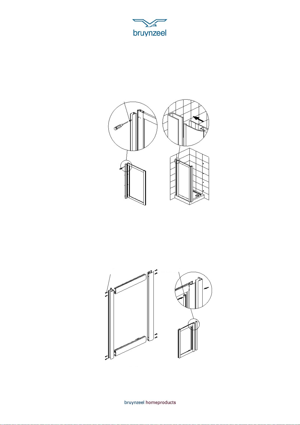
De draaideur 80/90 is zowel links- als rechtsdraaiend te monteren. In deze
montagehandleiding is het uitgangspunt een rechtsdraaiende deur. Lees na het
openen van de verpakking zorgvuldig de montagehandleiding door. Controleer of
alle onderdelen aanwezig zijn en of er geen transportschade is ontstaan. Mocht u
iets ontdekken, gelieve direct contact op te nemen met uw verkooppunt.
Benodigd gereedschap: electrische boormachine, beton boor (Ø 6 mm), aluminium
boor (Ø 3.2 mm), schroevendraaier (kruiskop), Rubber hamer, waterpas, meetlint,
potlood en siliconenkit.
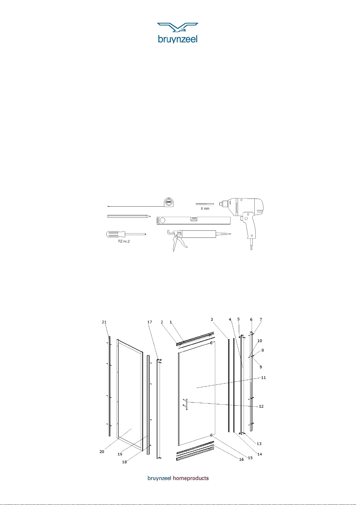
Onderdelen
1. Railprofiel 2x
2. Afwerkstrip horizontaal 2x
3. Afdichting verticaal 2x
4. Vast profiel scharnierzijde 1x
5. ST4x30 schroef 8x
6. Muurprofiel draaideur 1x
7. Afdekdopje 8x
8. ST4x30 schroef 8x
9. Sluitring 8x
10. Muurplug 8x
11. Draaideur 1x
12. Handgreep 1x
13. ST4x10 schroef 6x
(incl. afdekdopje, sluitring)
14. Afwerkstrip verticaal 2x
15. Draaipunt 2x
16. Afdichting horizontaal 1x
17. Vast profiel 1x
18. ST4x16 schroef 4x
19. Profiel draaideur (identiek
aan 6) 1x
20. Zijpaneel 1x
21. Muurprofiel zijpaneel 1x
22. Afwerkprofiel 1x (niet
zichtbaar op tekening)
1