REMEMBER
• Our taps must be installed by professional installers in accordance with current regulations and
recommendations in your country, and the specifications of the fluid engineer.
• Sizing the pipes correctly will avoid problems offlow rate, pressure loss and water hammer
(see calculation table in our brochure and online at www.delabie.com).
• Protect the installation with filters, water hammer absorbers and pressure reducers to reduce
the frequency of maintenance (recommended pressure from 1 to 5 bar maximum).
• Install stopcocks close to the tap to facilitate maintenance.
• The pipework, filters, non-return valves, stopcocks, bib taps, cartridge and all sanitary fittings should
be checked at least once ayear, and more frequently if necessary.
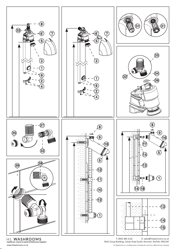
COMMISSIONING Fig. A, B, G, H & J
• Press the starter 1repeatedlyto purge the air until the automatic shut-off stabilises
(~ 30 sec. +5/ -10): the first cycles can last 57 minutes.
• Pressing on the starter 1, releases a jet ofwater. This causes the shower to open hydraulically.
Releasing the starter 1 will stop the jet of water.
SETTINGS Fig. A, B, C & O
• The water jet from the nozzle 5can be rotated through 20°. Apply pressure with yourthumb on the
nozzle 5and adjust to the desired position.
• The rotational position can be locked in place. To do this:
- Remove the nozzle 5using the tool 31 (supplied) (Fig. O).
- Using a 19mm spanner (not supplied), carefully tighten the nut 41.
- Replace the nozzle 5, taking care not to block it.
• The flow rate can be adjusted (Fig. A, B & C):
- Unscrewthe ring 3using the tool 31 (supplied), and remove the cover 7.
- Turn the stopcock 32 using a 3mm Allen key.
- Once the flow rate has been adjusted, replace the cover 7and the ring 3using the tool 31 supplied.
MAINTENANCE Fig. A, C, K, L, P & Q
Exposed, wall mounted, recessed or ceiling-mounted SPORTING shower model (Fig. L)
Dirt or abrasions on the O-rings on the starter:
• Turn off the water supply and remove the starter with a 23mm spanner (not supplied).
• Check/clean the O-rings 21 and 22.
• Replace the starter using a 23mm spanner and connect the water supply.
SPORTING panel
Dirt or abrasions on the O-rings on the starter (Fig. A, B, C & K):
• Using the tool 31 unscrew the ring 3and remove the cover 7(Fig. A & C or B & C).
• Turn off the water supply by closing the stopcock 32 (clockwise) (Fig. A or B).
• Unscrewthe two screws 4and remove the end cap 2(Fig. A or B).
• Remove the starter, partially loosening the holding screw 20 with a screwdriver (not supplied) (Fig. K).
• Remove the ring using a flat screwdriver, applying pressure to eject the starter 1. (Fig. K).
• Check/clean the O-rings 21 and 22 (Fig. K).
• Replace the starter and the ring: press fully on the starter then release; tighten the screw 20.
• Open the water supply by opening the stopcock 32 (anti-clockwise) (Fig. A or B).
• Replace the cover 7and tighten the ring 3using the tool 31 (Fig. A & C or B & C).
• Replace the end cap 2and tighten the two screws 4(Fig. A or B).
EN
After Sales Care Support:
The installation guide is available on: www.delabie.co.uk
For all other markets: Tel. +33 (0)3 22 60 22 74 - email: sav@delabie.fr
The installation guide is available on: www.delabie.com
Dirt or abrasions on the O-rings on the shower head mechanism (Fig. A, B, C, M, N & P):
• Using the tool 31, unscrew the ring 3and remove the cover 7
(Fig. A & C or B & C).
• Turn off the water supply by closing the stopcock 32 (clockwise) (Fig. A or B).
• Using a 30mm spanner, unscrew the mechanism body 42 (Fig. P).
• Remove the delay case 25, the spring 26 and the piston 27, taking care not to lose the washer 24
(Fig. M).
• Clean the inside ofthe delay case 25 with a cloth, and the timing groove 30 with a non-metallic point,
and check/clean the seals 28 and 29 (Fig. M & N).
• Replace the mechanism assembly not forgetting the washer 24 (Fig. M).
• Restore the water supply by opening the stopcock 32 (anti-clockwise) (Fig. A or B).
• Replace the cover 7and tighten the ring 3(Fig. A or B).
Cleaning the filter (Fig. A, B, C & Q):
•Using the tool 31, unscrew the ring 3and remove the cover 7
(Fig. A & C or B & C).
•Turn off the water supply by closing the stopcock 32 (clockwise) using a 3mm Allen key (not supplied)
(Fig. A or B).
•With the same Allen key, unscrew the filter holder 43 and clean the filter 44 (Fig. Q).
•Replace the filter 44 and the filter holder 43.
•Restore the water supply by opening the stopcock 32 (anti-clockwise) (Fig. A or B).
•Replace the cover 7and tighten the ring 3using the tool 31 or a pair of circlip pliers (Fig. A or B).
Frost protection (Fig. A, B, C & D):
•Shut off the mains water supply or the stopcock near the installed SPORTING shower.
•Press the starter 1on the SPORTING shower panel to reduce the pressure.
•Remove SPORTING panel:
- Using the tool 31, unscrew the ring 3and remove the cover 7 (Fig. A & C or B & C).
- Disconnect the panel from the inlet assembly 33 by unscrewing nut 34.
- Use a Phillips screwdriver to unscrew the two screws 4and remove the end cap 2(Fig. A or B).
- Remove the four screws 6and 6’ (Fig. A & B).
- Remove SPORTING panel and store it in a frost-free area.
CHEMICAL AND THERMAL SHOCKS
• The SPORTING is designed to withstand thermal and chemical shocks in line with current regulations
and guidelines.
MAINTENANCE & CLEANING
• Cleaning chrome and stainless steel: do not use abrasive, chlorine or any other acid-based
cleaning products. Clean with mild soapy water using a cloth or a sponge.
Clean with mild soapywater using a cloth or a sponge.
•Frost protection: drain the pipes and operate the tap several times to drain any remaining water.
In the event of prolonged exposure to frost, we recommend taking the mechanisms apart and storing
them indoors.