Bryant Preferred Series Installation and user guide

Manufacturer reserves the right to discontinue, or change at any time, specifications or designs without notice and without incurring obligations.
Catalog No. 04-53581021-01 Printed in U.S.A. Form SM581J-17-28-02 Pg 1 12-19 Replaces: SM581J-17-28-01
Service and Maintenance Instructions
CONTENTS
SAFETY CONSIDERATIONS . . . . . . . . . . . . . . . . . . . . . .1
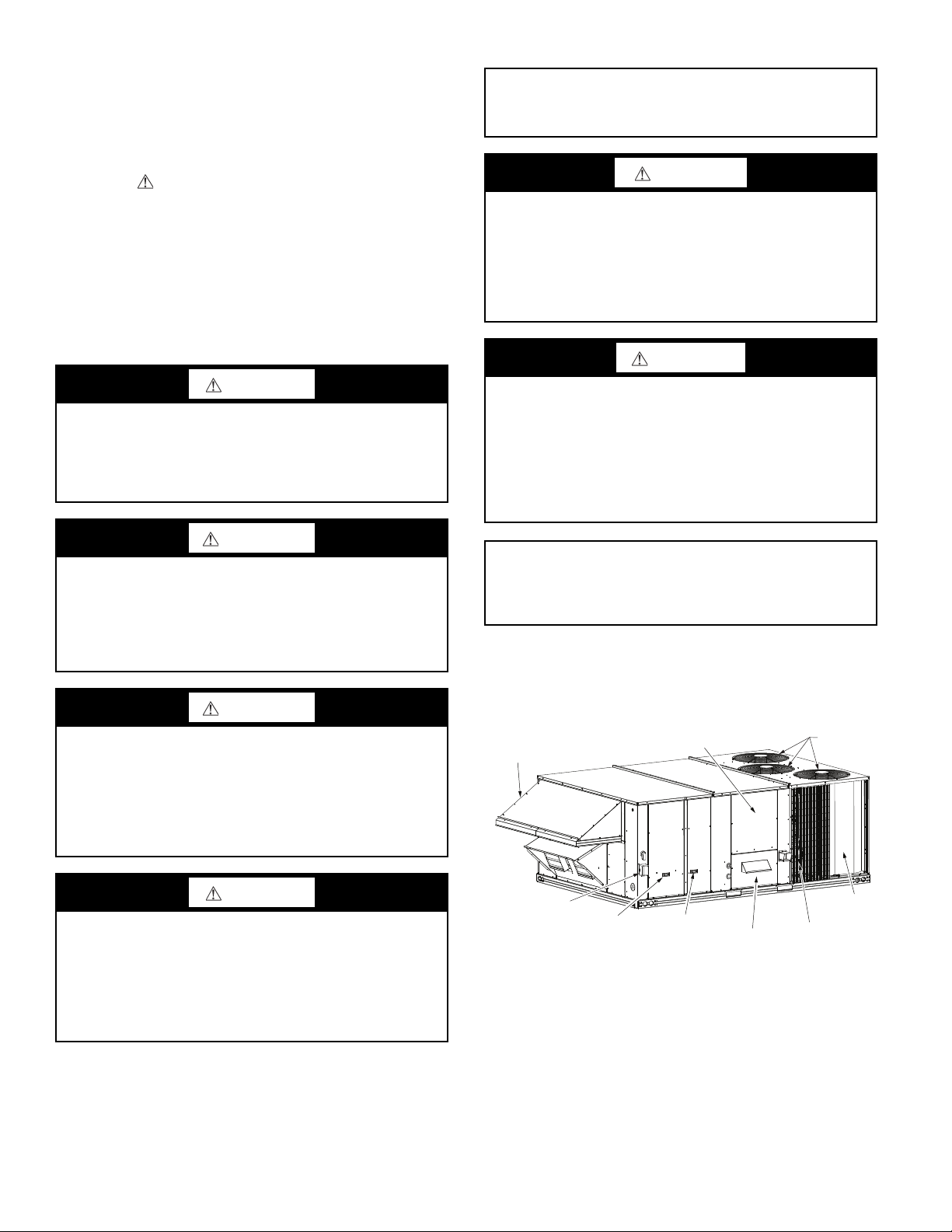
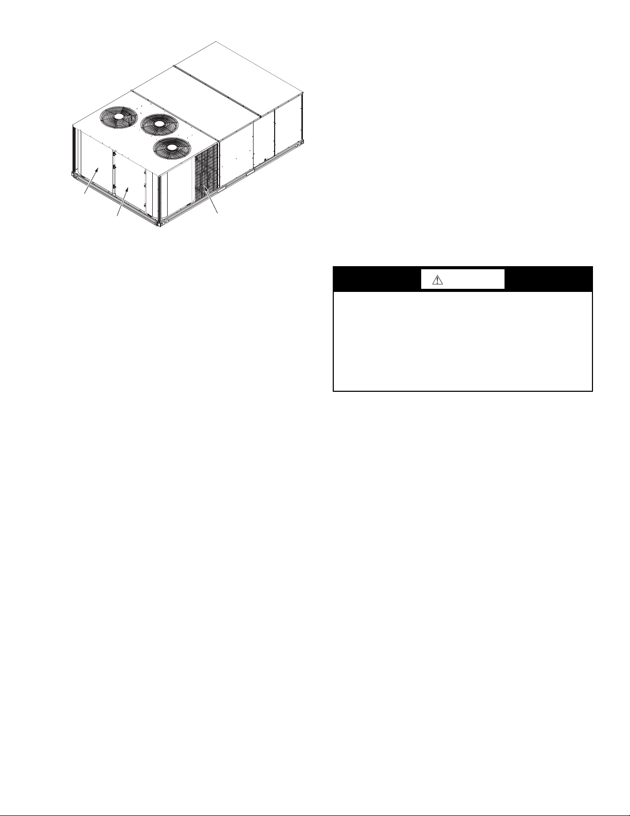
UNIT ARRANGEMENT AND ACCESS . . . . . . . . . . . . . .2
General . . . . . . . . . . . . . . . . . . . . . . . . . . . . . . . . . . . . . . . . . .2
Routine Maintenance. . . . . . . . . . . . . . . . . . . . . . . . . . . . . . .3
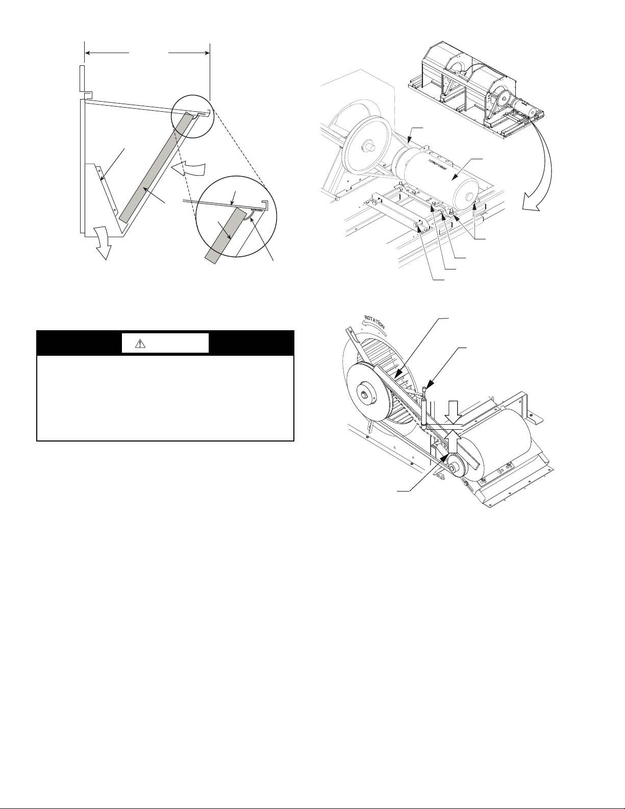
SUPPLY FAN (BLOWER) SECTION . . . . . . . . . . . . . . . .4
Supply Fan Assembly . . . . . . . . . . . . . . . . . . . . . . . . . . . . . .4
Belt . . . . . . . . . . . . . . . . . . . . . . . . . . . . . . . . . . . . . . . . . . . . .4
TWO-SPEED INDOOR FAN MOTOR SYSTEM:
2-SPEED FAN WITH VARIABLE FREQUENCY
DRIVE (VFD) . . . . . . . . . . . . . . . . . . . . . . . . . . . . . . . . . .5
Two-Speed Indoor Fan Motor System. . . . . . . . . . . . . . . . .5
Identifying Factory Option . . . . . . . . . . . . . . . . . . . . . . . . . .6
Unit Installation with 2-Speed Indoor Fan Motor Option.6
ADDITIONAL VFD INSTALLATION AND
TROUBLESHOOTING . . . . . . . . . . . . . . . . . . . . . . . . . .6
MOTOR . . . . . . . . . . . . . . . . . . . . . . . . . . . . . . . . . . . . . . . . .6
Replacing the Motor . . . . . . . . . . . . . . . . . . . . . . . . . . . . . . .6
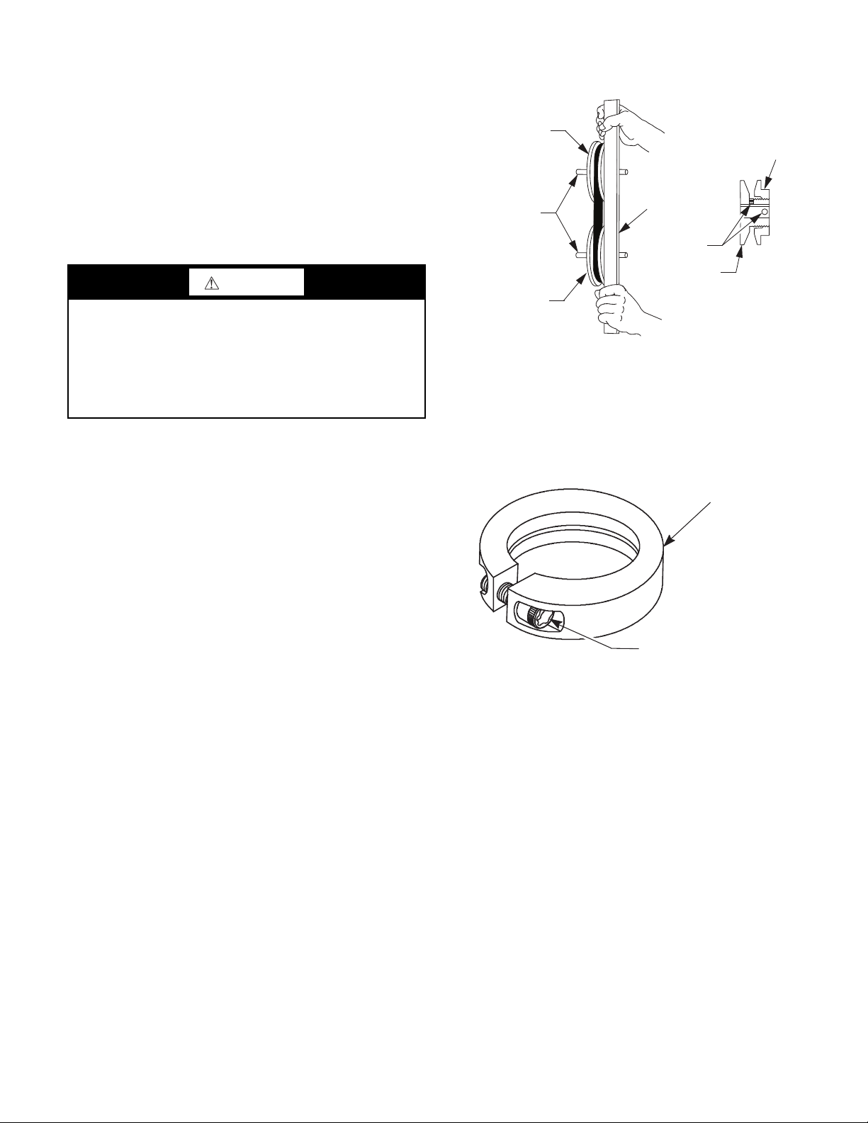
Changing Fan Wheel Speed by Changing Pulleys . . . . . . .7
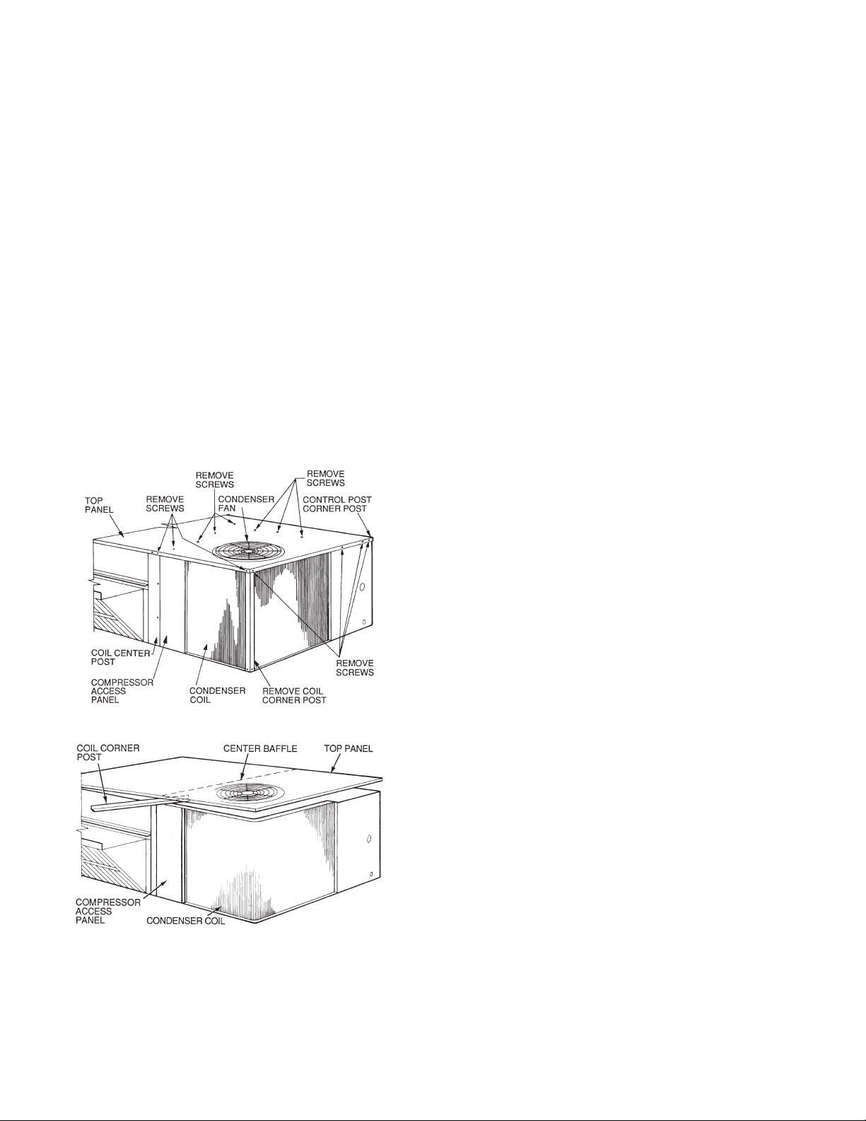
CONDENSER COIL SERVICE . . . . . . . . . . . . . . . . . . . . .7
Round Tube Plate Fin (RTPF) Condenser Coil . . . . . . . . .7
Recommended Condenser Coil Maintenance and
Cleaning . . . . . . . . . . . . . . . . . . . . . . . . . . . . . . . . . . . . . . .7
EVAPORATOR COILS . . . . . . . . . . . . . . . . . . . . . . . . . . . .8
Evaporator Coil . . . . . . . . . . . . . . . . . . . . . . . . . . . . . . . . . . .8
Coil Maintenance and Cleaning Recommendation . . . . . .8
Evaporator Coil Metering Devices. . . . . . . . . . . . . . . . . . . .9
Refrigerant System Pressure Access Ports . . . . . . . . . . . . .9
PERFECT HUMIDITY ADAPTIVE DEHUMIDIFICA-
TION SYSTEM. . . . . . . . . . . . . . . . . . . . . . . . . . . . . . . .10
Perfect Humidity Modes . . . . . . . . . . . . . . . . . . . . . . . . . . .10
Perfect Humidity System Components . . . . . . . . . . . . . . .10
Subcooler/Reheat Coil . . . . . . . . . . . . . . . . . . . . . . . . . . . . .11
Operating Sequences . . . . . . . . . . . . . . . . . . . . . . . . . . . . . .11
THERMOSTATIC EXPANSION VALVE (TXV). . . . . .15
TXV Operation . . . . . . . . . . . . . . . . . . . . . . . . . . . . . . . . . .15
Replacing TXV. . . . . . . . . . . . . . . . . . . . . . . . . . . . . . . . . . .16
Refrigerant System Pressure Access Ports . . . . . . . . . . . .16
PURON® (R-410A) REFRIGERANT. . . . . . . . . . . . . . . .16
Refrigerant Charge . . . . . . . . . . . . . . . . . . . . . . . . . . . . . . .16
COOLING CHARGING CHARTS. . . . . . . . . . . . . . . . . .18
COMPRESSORS. . . . . . . . . . . . . . . . . . . . . . . . . . . . . . . . .22
Lubrication. . . . . . . . . . . . . . . . . . . . . . . . . . . . . . . . . . . . . .22
Replacing the Compressor . . . . . . . . . . . . . . . . . . . . . . . . .22
Filter Drier . . . . . . . . . . . . . . . . . . . . . . . . . . . . . . . . . . . . . .22
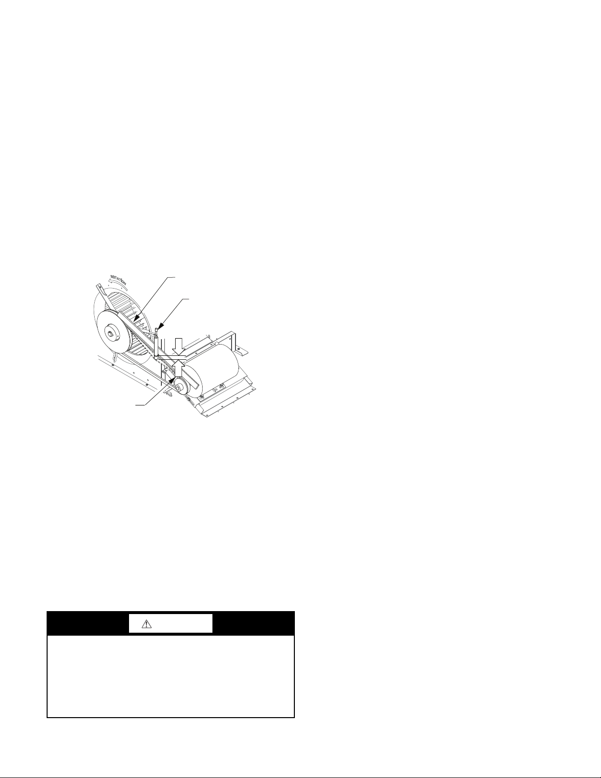
Adjusting the Condenser-Fan. . . . . . . . . . . . . . . . . . . . . . .22
TROUBLESHOOTING COOLING SYSTEM . . . . . . . .22
Troubleshooting Cooling System . . . . . . . . . . . . . . . . . . . .22
CONVENIENCE OUTLETS . . . . . . . . . . . . . . . . . . . . . . .24
Non-Powered Type . . . . . . . . . . . . . . . . . . . . . . . . . . . . . . .24
Unit-Powered Type . . . . . . . . . . . . . . . . . . . . . . . . . . . . . . .24
Wet in Use Convenience Outlet Cover. . . . . . . . . . . . . . . .24
Duty Cycle . . . . . . . . . . . . . . . . . . . . . . . . . . . . . . . . . . . . . .24
GFCI Maintenance . . . . . . . . . . . . . . . . . . . . . . . . . . . . . . .24
Fuse On Powered Type . . . . . . . . . . . . . . . . . . . . . . . . . . . . 25
Using Unit-Mounted Convenience Outlets . . . . . . . . . . . . 25
Installing a Weatherproof Cover . . . . . . . . . . . . . . . . . . . . 25
SMOKE DETECTORS . . . . . . . . . . . . . . . . . . . . . . . . . . . 25
System. . . . . . . . . . . . . . . . . . . . . . . . . . . . . . . . . . . . . . . . . . 25
Controller. . . . . . . . . . . . . . . . . . . . . . . . . . . . . . . . . . . . . . . 25
Sensor . . . . . . . . . . . . . . . . . . . . . . . . . . . . . . . . . . . . . . . . . . 26
Smoke Detector Locations . . . . . . . . . . . . . . . . . . . . . . . . . 26
FIOP Smoke Detector Wiring and Response . . . . . . . . . . 28
Sensor and Controller Tests . . . . . . . . . . . . . . . . . . . . . . . . 29
Detector Cleaning . . . . . . . . . . . . . . . . . . . . . . . . . . . . . . . . 30
INDICATORS . . . . . . . . . . . . . . . . . . . . . . . . . . . . . . . . . . . 30
Normal State . . . . . . . . . . . . . . . . . . . . . . . . . . . . . . . . . . . . 30
Alarm State . . . . . . . . . . . . . . . . . . . . . . . . . . . . . . . . . . . . . 30
Troubleshooting. . . . . . . . . . . . . . . . . . . . . . . . . . . . . . . . . . 31
PROTECTIVE DEVICES . . . . . . . . . . . . . . . . . . . . . . . . . 31
Compressor Protection . . . . . . . . . . . . . . . . . . . . . . . . . . . . 31
Supply (Indoor) Fan Motor Protection . . . . . . . . . . . . . . . 31
Control Circuit, 24-v . . . . . . . . . . . . . . . . . . . . . . . . . . . . . . 32
RTU-OPEN CONTROL SYSTEM . . . . . . . . . . . . . . . . . . 32
GAS HEATING SYSTEM . . . . . . . . . . . . . . . . . . . . . . . . . 32
General . . . . . . . . . . . . . . . . . . . . . . . . . . . . . . . . . . . . . . . . . 32
Fuel Types and Pressures . . . . . . . . . . . . . . . . . . . . . . . . . . 32
Flue Gas Passageways. . . . . . . . . . . . . . . . . . . . . . . . . . . . . 33
Combustion-Air Blower . . . . . . . . . . . . . . . . . . . . . . . . . . . 33
Burners and Igniters . . . . . . . . . . . . . . . . . . . . . . . . . . . . . . 34
Gas Valve . . . . . . . . . . . . . . . . . . . . . . . . . . . . . . . . . . . . . . . 37
ECONOMI$ER SYSTEMS . . . . . . . . . . . . . . . . . . . . . . . . 44
EconoMi$er IV Standard Sensors . . . . . . . . . . . . . . . . . . . 48
EconoMi$er® X (Factory Option). . . . . . . . . . . . . . . . . . . 54
PRE-START-UP/START-UP . . . . . . . . . . . . . . . . . . . . . . 67
START-UP, GENERAL . . . . . . . . . . . . . . . . . . . . . . . . . . . 67
Unit Preparation . . . . . . . . . . . . . . . . . . . . . . . . . . . . . . . . . 67
Additional Installation/Inspection . . . . . . . . . . . . . . . . . . . 67
FASTENER TORQUE VALUES . . . . . . . . . . . . . . . . . . . 69
APPENDIX A — MODEL NUMBER
NOMENCLATURE . . . . . . . . . . . . . . . . . . . . . . . . . . . . 70
APPENDIX B — PHYSICAL DATA . . . . . . . . . . . . . . . . 71
APPENDIX C — FAN PERFORMANCE . . . . . . . . . . . . 75
APPENDIX D — WIRING DIAGRAMS . . . . . . . . . . . . . 83
APPENDIX E — MOTORMASTER SENSOR
LOCATIONS . . . . . . . . . . . . . . . . . . . . . . . . . . . . . . . . . 94
START-UP CHECKLIST . . . . . . . . . . . . . . . . . . . . . . CL-1
SAFETY CONSIDERATIONS
Installation and servicing of air-conditioning equipment can be
hazardous due to system pressure and electrical components. Only
trained and qualified service personnel should install, repair, or
service air-conditioning equipment.
Untrained personnel can perform basic maintenance functions of
cleaning coils and filters and replacing filters. All other operations
should be performed by trained service personnel. When working
on air-conditioning equipment, observe precautions in the litera-
Preferred Series™
581J*17-28
Gas Heat/Electric Cooling
with Puron®(R-410A) Refrigerant

2
ture, tags and labels attached to the unit, and other safety precau-
tions that may apply.
Follow all safety codes, including ANSI (American National Stan-
dards Institute) Z223.1. Wear safety glasses and work gloves. Use
quenching cloth for unbrazing operations. Have fire extinguisher
available for all brazing operations.
It is important to recognize safety information. This is the safety-
alert symbol . When you see this symbol on the unit and in in-
structions or manuals, be alert to the potential for personal injury.
Understand the signal words DANGER, WARNING, CAUTION,
and NOTE. These words are used with the safety-alert symbol.
DANGER identifies the most serious hazards which will result in
severe personal injury or death. WARNING signifies hazards
which could result in personal injury or death. CAUTION is used
to identify unsafe practices, which may result in minor personal
injury or product and property damage. NOTE is used to highlight
suggestions which will result in enhanced installation, reliability,
or operation.
UNIT ARRANGEMENT AND ACCESS
General
Figures 1 and 2 show general unit arrangement and access
locations.
Fig. 1 — Access Panels and Components (Front)
CAUTION
PERSONAL INJURY HAZARD
Failure to follow this caution may result in personal injury.
Sheet metal parts may have sharp edges or burrs. Use care and
wear appropriate protective clothing, safety glasses and gloves
when handling parts and servicing air conditioning equipment.
WARNING
FIRE, EXPLOSION HAZARD
Failure to follow this warning could result in death, serious
personal injury and/or property damage.
Never use air or gases containing oxygen for leak testing or for
operating refrigerant compressors. Pressurized mixtures of air
or gases containing oxygen can lead to an explosion.
WARNING
FIRE, EXPLOSION HAZARD
Failure to follow this warning could result in death, serious
personal injury and/or property damage.
Never use non-certified refrigerants in this product. Non-certi-
fied refrigerants could contain contaminates that could lead to
unsafe operating conditions. Use ONLY refrigerants that con-
form to AHRI Standard 700.
CAUTION
UNIT DAMAGE HAZARD
Failure to follow this caution may result in reduced unit perfor-
mance or unit shutdown.
High velocity water from a pressure washer, garden hose, or
compressed air should never be used to clean a coil. The force
of the water or air jet will bend the fin edges and increase air-
side pressure drop.
IMPORTANT: Pressing the controller’s test/reset switch for
longer than seven seconds will put the duct detector into the
alarm state and activate all automatic alarm responses.
CAUTION
ELECTRICAL SHOCK HAZARD
Failure to follow this warning could cause personal injury or
death.
Before performing service or maintenance operations on the
fan system, shut off all unit power and lockout/tag-out the unit
disconnect switch. DO NOT reach into the fan section with
power still applied to unit.
WARNING
ELECTRICAL OPERATION HAZARD
Failure to follow this warning could result in personal injury or
death.
Units with convenience outlet circuits may use multiple
disconnects. Check convenience outlet for power status before
opening unit for service. Locate its disconnect switch, if
appropriate, and open it. Lock-out and tag-out this switch, if
necessary.
IMPORTANT: Lockout/tag-out is a term used when electri-
cal power switches are physically locked preventing power
to the unit. A placard is placed on the power switch alerting
service personnel that the power is disconnected.
OUTDOOR AIR
HOOD
CONTROL BOX
ACCESS PANEL RETURN AIR
FILTER AND
INDOOR COIL
ACCESS PANEL
SUPPLY FAN
HEATING SECTION
GAS SECTION
ACCESS PANEL
OUTDOOR
FANS/MOTORS
DISCONNECT
CONVENIENCE
OUTLET
COMPRESSOR
(CIRCUIT A)
CONDENSER
COIL
(CIRCUIT A)

3
Fig. 2 — Typical Access Panel Location (Rear)
Routine Maintenance
These items should be part of a routine maintenance program, to
be checked every month or two, until a specific schedule for each
can be identified for this installation.
QUARTERLY INSPECTION (AND 30 DAYS AFTER INI-
TIAL START)
The 581J units should be inspected and serviced every three
months.
• Return air filter replacement
• Outdoor hood inlet filters cleaned
• Belt tension checked
• Belt condition checked
• Pulley alignment checked
• Fan shaft bearing locking collar tightness checked
• Condenser coil cleanliness checked
• Condensate drain checked
SEASONAL MAINTENANCE
These items should be checked at the beginning of each season (or
more often if local conditions and usage patterns dictate).
Air Conditioning
• Condenser fan motor mounting bolts tightness
• Compressor mounting bolts
• Condenser fan blade positioning
• Control box cleanliness and wiring condition
• Wire terminal tightness
• Refrigerant charge level
• Evaporator coil cleaning
• Evaporator blower motor amperage
Heating
• Heat exchanger flue passageways cleanliness
• Gas burner condition
• Gas manifold pressure
• Heating temperature rise
Economizer or Outside Air Damper
• Inlet filters condition
• Check damper travel (economizer)
• Check gear and dampers for debris and dirt
Air Filters and Screens
Each unit is equipped with return air filters. If the unit has an econ-
omizer, it will also have an outside air screen. If a manual outside
air damper is added, an inlet air screen will also be present.
Each of these filters and screens will need to be periodically re-
placed or cleaned.
Return Air Filters
Return air filters are disposable fiberglass media type. Access to
the filters is through the vertical panel to the right of the control
box. Filters are situated on slide-out racks for easy inspection and
repair. See Fig. 1.
Removing the Return Air Filters
1. Remove the return air filter and indoor coil access panel.
See Fig. 1.
2. Reach inside and remove the filters from the filter rack.
3. Replace the filters, as required, with similar replacement
filters of the same size.
4. Re-install the return air filter and indoor coil access panel.
Outdoor Air Hood
The outdoor air hood inlet screens are permanent aluminum-mesh
type filters. See Fig. 2. Inspect these screens for cleanliness. Re-
move the screens when cleaning is required. Clean by washing
with hot low-pressure water and soft detergent. Replace all screens
before restarting the unit. Observe the flow direction arrows on the
side of each screen frame.
Economizer Inlet Air Screen
The inlet air screen is retained by filter clips under the top edge of
the hood. See Fig. 3.
Remove screens by removing the screws in the horizontal clips on
the leading edge of the hood. Slide filters out. See Fig. 3.
Install filters, by sliding clean or new filters into the hood side re-
tainers. Once positioned, re-install the horizontal clips.
CONDENSER COIL
CIRCUIT A
CONDENSER COIL
CIRCUIT B
COMPRESSOR
CIRCUIT B
CAUTION
EQUIPMENT DAMAGE HAZARD
Failure to follow this CAUTION can result in premature wear
and damage to equipment.
DO NOT OPERATE THE UNIT WITHOUT THE RETURN
AIR FILTERS IN PLACE.
Dirt and debris can collect on heat exchangers and coils possi-
bly resulting in a small fire. Dirt buildup on components can
cause excessive current used resulting in motor failure.

4
Fig. 3 — Inlet Air Screen Installation
SUPPLY FAN (BLOWER) SECTION
Supply Fan Assembly
The supply fan system consists of two forward-curved centrifugal
blower wheels mounted on a solid blower shaft that is supported
by two greaseable pillow block concentric bearings. A fixed-pitch
driven fan pulley is attached to the fan shaft and an adjustable-
pitch driver pulley is mounted on the motor. The pulleys are con-
nected using a V-belt. See Fig. 4.
Belt
Check the belt condition and tension quarterly. Inspect the belt for
signs of cracking, fraying or glazing along the inside surfaces.
Check belt tension by using a spring-force tool, such as Brown-
ing’s “Belt Tension Checker” (P/N: 1302546 or equivalent tool);
tension should be 6 lb at a 5/8-in. (1.6 cm) deflection when mea-
sured at the centerline of the belt span. This point is at the center of
the belt when measuring the distance between the motor shaft and
the blower shaft. See Fig. 5.
NOTE: Without the spring-tension tool, place a straight edge
across the belt surface at the pulleys, then push down on the belt at
mid-span using one finger until a 1/2-in. (1.3 cm) deflection is
reached.
Fig. 4 — Belt Drive Motor Mounting
Fig. 5 — Checking Blower Motor Belt Tension
ADJUSTING THE BELT TENSION
Use the following steps to adjust the V-belt tension. See Fig. 4.
1. Loosen the four motor mounting nuts that attach the motor
to the blower rail.
2. Loosen the two jackbolt locking nuts beneath the motor
mounting plate. Turn the jackbolt locking nut counter-
clockwise to loosen.
3. Turn the jack bolts counterclockwise to loosen and clock-
wise to tighten.
4. Adjust the V-belt for proper tension.
5. Ensure the fan shaft and the motor shaft are parallel prior
to tightening motor mounting nuts. See Fig. 6.
6. Make adjustments as necessary.
7. Tighten the four motor mounting nuts.
8. Check the V-belt tension. Make adjustments as necessary.
9. Re-tighten the four motor mounting nuts.
10. Tighten both jackbolt locking nuts securely.
CAUTION
ELECTRICAL SHOCK HAZARD
Failure to follow this warning could cause personal injury or
death.
Before performing service or maintenance operations on the
fan system, shut off all unit power and lockout/tag-out the unit
disconnect switch. DO NOT reach into the fan section with
power still applied to unit.
17 1/4”
DIVIDER
BAROMETRIC
RELIEF
CLEANABLE
ALUMINUM
FILTER FILTER
HOOD
FILTER
CLIP
OUTSIDE
AIR
MOTOR
V-BELT
MOTOR ADJUSTMENT
BOLTS(4)
JACKBOLT LOCKING NUT (2)
MOTOR MOUNTING PLATE
JACKBOLT (2)
BROWNING BELT
TENSION CHECKER
STRAIGHTEDGE
1/2”
(1.3 cm)
BELT
DEFLECTION

5
REPLACING THE V-BELT
1. Use a belt with same section type or similar size. Do not
substitute a “FHP” or “notched” type V-belt.
2. Loosen (turn counterclockwise) the motor mounting plate
front bolts and rear bolts. See Fig. 4.
3. Loosen (turn counterclockwise) the jack bolt lock nuts.
Loosen (turn counterclockwise) the jack bolts relieving the
belt tension allowing easy removal of the belt by hand.
4. Remove the belt by gently lifting the old belt over one of
the pulleys.
5. Install the new belt by gently sliding the belt over both
pulleys, then tighten (turn clockwise) the jack bolts sliding
the motor plate away from the fan housing until proper
belt tension is achieved.
6. Check the alignment of the pulleys and adjust if necessary.
See Fig 6.
7. Tighten all bolts attaching the motor to the motor plate.
8. Tighten all jack bolt jam nuts by turning clockwise.
9. Check the tension after a few hours of runtime and re-
adjust as required. See Fig. 5.
ADJUSTABLE-PITCH PULLEY ON MOTOR
The motor pulley is an adjustable-pitch type that allows a servicer
to implement changes in the fan wheel speed to match as-installed
ductwork systems. The pulley consists of a fixed flange side that
faces the motor (secured to the motor shaft) and a movable flange
side that can be rotated around the fixed flange side that increases
or reduces the pitch diameter of this driver pulley. See Fig. 6.
As the pitch diameter is changed by adjusting the position of the
movable flange, the centerline on this pulley shifts laterally, along
the motor shaft. This creates a requirement for a realignment of
the pulleys after any adjustment of the movable flange. Also reset
the belt tension after each realignment. The factory setting of the
adjustable pulley is five turns open from full closed.
Check the condition of the motor pulley for signs of wear. Glazing
of the belt contact surfaces and erosion on these surfaces are signs
of improper belt tension and/or belt slippage. Pulley replacement
can be necessary.
CHANGING FAN SPEED:
1. Shut off unit power supply and apply approved lock-out/
tag-out procedures.
2. Loosen belt by loosening the motor adjustment bolts as
described in the Belt Adjustment section above. See
Fig. 4.
3. Loosen movable pulley flange setscrew. See Fig. 6.
4. Screw movable flange toward fixed flange to increase
speed and away from fixed flange to decrease speed.
Increasing fan speed increases load on motor. Do not
exceed maximum fan speed in the product data or motor
amperage as listed on the unit rating plate.
5. Set movable flange at nearest keyway or flat of pulley hub
and tighten setscrew to torque specifications. Torque pul-
ley set screw to 72 ± 5 in.-lb (8.14 ± 0.56 Nm).
ALIGNING THE FAN AND MOTOR PULLEYS:
1. Loosen fan pulley setscrews.
2. Slide fan pulley along fan shaft. Make angular alignment
by loosening motor from mounting. See Fig. 6.
3. Tighten fan pulley setscrews and motor mounting bolts to
torque specifications.
4. Recheck belt tension. See Fig. 5.
Fig. 6 — Supply-Fan Pulley Adjustment
BEARINGS
This fan system uses bearings featuring concentric split locking
collars. The collars are tightened through a cap screw bridging the
split portion of the collar. The cap screw has a Torx T25 socket
head. To tighten the locking collar: Hold the locking collar tightly
against the inner race of the bearing and torque the cap screw to 65
to 70 in.-lb (7.4-7.9 Nm). See Fig. 7.
Fig. 7 — Tightening Locking Collar
TWO-SPEED INDOOR FAN MOTOR SYSTEM:
2-SPEED FAN WITH VARIABLE FREQUENCY
DRIVE (VFD)
Two-Speed Indoor Fan Motor System
NOTE: The 2-speed indoor fan motor option is not available on
units with Perfect Humidity™ adaptive humidification system.
The 2-speed indoor fan motor system utilizes a fan speed control
board and Variable Frequency Drive (VFD) to automatically ad-
just the indoor fan motor speed in sequence with the unit’s venti-
lation, cooling and heating operation. Conforming to ASHRAE
90.1 2010 Standard Section 6.4.3.10.b, during the first stage of
cooling operation the 2-speed indoor fan motor system will ad-
just the fan motor to provide two-thirds (2/3) of the design air-
flow rate for the unit. When the call for the second stage of cool-
ing is required, the 2-speed indoor fan motor system will allow
the design airflow rate for the unit established (100%). During
the heating mode, the 2-speed indoor fan motor system will al-
low total design airflow rate (100%) operation. During ventila-
tion mode, the 2-speed indoor fan motor system will operate the
fan motor at 2/3speed.
CAUTION
EQUIPMENT DAMAGE HAZARD
Failure to follow this CAUTION can result in premature wear
and damage to equipment.
Do not use a screwdriver or a pry bar to place the new V-belt in
the pulley groove. This can cause stress on the V-belt and the
pulley resulting in premature wear on the V-belt and damage
to the pulley.
STRAIGHT EDGE
MUST BE PARALLEL
WITH BELT
SETSCREWS
MOTOR AND
FANSHAFTS
MUST BE
PARALLEL
FIXED FLANGE
MOVABLE
FLANGE
SINGLE - GROOVE
FAN PULLEY
MOTOR PULLEY
T --- 2 5 T O R X S O C K E T
HEAD CAP SCREW
LOCKING COLLAR

6
Identifying Factory Option
This section only applies to units that meet the criteria detailed
in Table 1. If the unit does not meet that criteria, disregard this
section.
NOTE: See Fig. A in Appendix A for the model number
nomenclature.
Unit Installation with 2-Speed Indoor Fan Motor
Option
581J ROOFTOP
Refer to the base unit installation instructions for standard required
operating and service clearances.
NOTE: The Remote VFD Keypad is a field-installed option. It is
not included as part of the factory-installed VFD option. See Va r i -
able Frequency Drive (VFD) Installation, Setup and Trouble-
shooting Supplement for wiring schematics, performance charts,
and configuration. See Fig. 8 for location of the VFD as mounted
on the various 581J models.
Fig. 8 — VFD Location for 581J 17-28 Units
ADDITIONAL VFD INSTALLATION AND
TROUBLESHOOTING
Additional installation, wiring and troubleshooting information
for the VFD can be found in the following manual: Variable Fre-
quency Drive (VFD) Installation, Setup and Troubleshooting
Supplement.
MOTOR
When replacing the motor, use the following steps. See Fig. 9.
Fig. 9 — Replacing Belt-Driven Motor
Replacing the Motor
Use the following steps to replace the belt-driven motor.
1. Turn off all electrical power to the unit. Use approved
lockout/tag-out procedures on all electrical power sources.
2. Remove cover on motor connection box.
3. Disconnect all electrical leads to the motor.
4. Loosen the two jack bolt jamnuts on the motor mounting
bracket.
5. Turn two jack bolts counterclockwise until motor assem-
bly moves closer to blower pulley.
6. Remove V-belt from blower pulley and motor pulley.
7. Loosen the four mounting bracket bolts and lock washers.
8. Remove four bolts, four flat washers, four lock washers
and four nuts attaching the motor mounting plate to the
unit. Discard all lock washers.
9. Remove motor and motor mounting bracket from unit.
10. Remove four bolts, flat washers, lock washers and single
external-tooth lock washer attaching motor to the motor
mounting plate. Discard all lock washers and external-
tooth lock washer.
11. Lift motor from motor mounting plate and set aside.
12. Slide motor mounting band from old motor.
13. Slide motor mounting band onto new motor and set motor
onto the motor mounting plate.
14. Remove variable pitch pulley from old motor and attach it
to the new motor.
15. Inspect variable pitch pulley for cracks and wear. Replace
the pulley if necessary.
16. Secure the pulley to the motor by tightening the pulley set-
screw to the motor shaft.
17. Insert four bolts and flat washers through mounting holes
on the motor into holes on the motor mounting plate.
18. On one bolt, place a new external-tooth lock washer
between the motor and motor mounting band.
19. Ensure the teeth of the external-tooth lock washer make
contact with the painted base of the motor. This washer is
essential for properly grounding motor.
20. Install four new lock washers and four nuts on the bolts on
the bottom of the motor mounting plate.
Table 1 — Model Size/VFD Option Indicator
MODEL/SIZES POSITION IN
MODEL NUMBER
VFD FIOP
INDICATOR
581J 17-28 17 D
VARIABLE
FREQUENCY
DRIVE (VFD)
CAUTION
EQUIPMENT DAMAGE HAZARD
Failure to follow this CAUTION can result in premature wear
and damage to equipment.
Do not use a screwdriver or a pry bar to place the new V-belt in
the pulley groove. This can cause stress on the V-belt and the
pulley resulting in premature wear on the V-belt and damage
to the pulley.
BLOWER PULLEY
V-BELT
MOTOR PULLEY
MOTOR
MOTOR MOUNTING
BRACKET BOLTS (4)
MOTOR MOUNTING
BRACKET (2)
JACK BOLT JAM NUT (2)
JACK BOLT (2)

7
21. Do not tighten the mounting bolts at this time.
22. Set new motor and motor mounting bracket back onto the
unit. See Fig. 9.
23. Install four bolts, four flat washers, four new lock washers
and four nuts attaching the motor assembly to the unit.
24. Do not tighten the mounting bolts at this time.
25. Install motor drive V-belt to motor pulley and blower
wheel pulley. See CAUTION.
26. Align the motor pulley and blower wheel pulley using a
straight edge. See Fig. 6.
27. Adjust the V-belt tension using adjustment tool.
28. Turn two jack bolts clockwise, moving the motor assembly
away from the blower pulley, increasing the V-belt tension.
29. Tighten the four bolts securing the motor mounting brack-
ets to the unit. Torque four bolts to 120 ± 12 in.-lb (14 ±
1.4 Nm).
30. Remove cover on motor connection box.
31. Re-connect all electrical leads to the motor and replace the
connection box cover.
32. Re-connect all electrical power to the unit. Remove lock-
out tags on all electrical power sources.
33. Start unit and allow to run for a designated period.
34. Shut off unit and make any necessary adjustments to the V-
belt tension or the motor and blower wheel pulley alignment.
Fig. 10 — Adjusting V-belt Tension
Changing Fan Wheel Speed by Changing Pulleys
The horsepower rating of the belt is primarily dictated by the pitch
diameter of the smaller pulley in the drive system (typically the
motor pulley in these units). Do not install a replacement motor
pulley with a smaller pitch diameter than provided on the original
factory pulley. Change fan wheel speed by changing the fixed fan
pulley (larger pitch diameter to reduce wheel speed, smaller pitch
diameter to increase wheel speed) or select a new system with
both pulleys and matching belt(s).
Before changing pulleys to increase fan wheel speed, check the
fan performance at the target speed and airflow rate to determine
new motor loading (bhp). Use the fan performance tables or use
the Packaged Rooftop Builder software program. Confirm that the
motor in this unit is capable of operating at the new operating con-
dition. Fan shaft loading increases dramatically as wheel speed is
increased.
To reduce vibration, replace the motor’s adjustable pitch pulley
with a fixed pitch pulley (after the final airflow balance adjust-
ment). This will reduce the amount of vibration generated by the
motor/belt-drive system.
To determine variable pitch pulley diameter, perform the follow-
ing calculation:
1. Determine full open and full closed pulley diameter.
2. Subtract the full open diameter from the full closed diameter.
3. Divide that number by the number of pulley turns open
from full closed.
This number is the change in pitch datum per turn open.
EXAMPLE
• Pulley dimensions 2.9 to 3.9-in. (full close to full open)
• 3.9 – 2.9 = 1-in.
• 1 divided by 5 (turns from full close to full open)
• 0.2 change in pulley diameter per turn open
• 2.9 + 0.2 = 3.1-in. pulley diameter when pulley closed one
turn from full open
CONDENSER COIL SERVICE
Round Tube Plate Fin (RTPF) Condenser Coil
The condenser coil is fabricated with round copper hairpins tubing
and plate fins of various materials and coatings (see Appendix A
to identify the materials provided in this unit). The coil can be one-
row or composite-type two-row. Composite two-row coils are two
single-row coils fabricated with a single return bend end
tubesheet.
Recommended Condenser Coil Maintenance and
Cleaning
Routine cleaning of coil surfaces is essential to maintain proper
operation of the unit. Elimination of contamination and removal of
harmful residues will greatly increase the life of the coil and ex-
tend the life of the unit. The following maintenance and cleaning
procedures are recommended as part of the routine maintenance
activities to extend the life of the coil.
REMOVE SURFACE LOADED FIBERS
Surface loaded fibers or dirt should be removed with a vacuum
cleaner. If a vacuum cleaner is not available, a soft non-metallic
bristle brush can be used. In either case, the tool should be applied
in the direction of the fins. Coil surfaces can be easily damaged
(fin edges can be easily bent over and damage to the coating of a
protected coil) if the tool is applied across the fins.
NOTE: Use of a water stream, such as a garden hose, against a
surface loaded coil will drive the fibers and dirt into the coil. This
will make cleaning efforts more difficult. Surface loaded fibers
must be completely removed prior to using low velocity clean wa-
ter rinse.
PERIODIC CLEAN WATER RINSE
A periodic clean water rinse is very beneficial for coils that are ap-
plied in coastal or industrial environments. However, it is very im-
portant that the water rinse is made with a very low velocity water
stream to avoid damaging the fin edges. Monthly cleaning, as de-
scribed below, is recommended.
ROUTINE CLEANING OF COIL SURFACES
Periodic cleaning with Totaline®, environmentally sound coil
cleaner, is essential to extend the life of coils. This cleaner is avail-
able from Replacement Components Division as part number
P902-0301 for a one gallon container, and part number P902-0305
for a 5 gallon container. It is recommended that all coils, including
standard aluminum, pre-coated, copper/copper or E-coated coils,
be cleaned with the Totaline environmentally sound coil cleaner as
described below. Coil cleaning should be part of the unit’s regular-
ly scheduled maintenance procedures to ensure long life of the
CAUTION
EQUIPMENT DAMAGE HAZARD
Failure to follow this caution can result in equipment damage.
Drive packages cannot be changed in the field. For example: a
standard drive cannot be changed to a high static drive. This
type of change will alter the unit’s certification and could re-
quire heavier wiring to support the higher amperage draw of
the drive package.
BROWNING BELT
TENSION CHECKER
STRAIGHTEDGE
1/2”
(1.3 cm)
BELT
DEFLECTION

8
coil. Failure to clean the coils can result in reduced durability in
the environment.
Avoid use of:
• coil brighteners
• acid cleaning prior to painting
• high pressure washers
• poor quality water for cleaning
Totaline environmentally sound coil cleaner is nonflammable, hy-
poallergenic, non-bacterial, and a USDA accepted biodegradable
agent that will not harm the coil or surrounding components such
as electrical wiring, painted metal surfaces, or insulation. Use of
non-recommended coil cleaners is strongly discouraged since coil
and unit durability could be affected.
TWO-ROW COILS
Clean coil as follows:
1. Turn off unit power, tag disconnect.
2. Remove top panel screws on condenser end of unit.
3. Remove condenser coil corner post. (See Fig. 11.) To hold
top panel open, place coil corner post between top panel
and center post. See Fig. 12.
4. Remove screws securing coil to compressor plate and
compressor access panel.
5. Remove fastener holding coil sections together at return
end of condenser coil. Carefully separate the outer coil
section 3-in. to 4-in. from the inner coil section. See
Fig. 12.
Fig. 11 — Cleaning Condenser Coil
Fig. 12 — Propping Up Top Panel
EVAPORATOR COILS
Evaporator Coil
The evaporator coil uses the traditional round-tube, plate-fin
(RTPF) technology. Tube and fin construction consists of vari-
ous optional materials and coatings (see Appendix A). Coils are
multiple-row. On two compressor units, the evaporator coil is a
face split design, meaning the two refrigerant circuits are inde-
pendent in the coil. The bottom portion of the coil will always be
circuit A, with the top of the coil being circuit B.
Coil Maintenance and Cleaning Recommendation
Routine cleaning of coil surfaces is essential to maintain proper
operation of the unit. Elimination of contamination and removal of
harmful residues will greatly increase the life of the coil and ex-
tend the life of the unit. The following maintenance and cleaning
procedures are recommended as part of the routine maintenance
activities to extend the life of the coil.
REMOVING SURFACE LOADED FIBERS
Surface loaded fibers or dirt should be removed with a vacuum
cleaner. If a vacuum cleaner is not available, a soft non-metallic
bristle brush can be used. In either case, the tool should be applied
in the direction of the fins. Coil surfaces can be easily damaged.
Applying the tool across the fin edges can cause the edges to be
easily bent over, damaging the coating of a protected coil.
NOTE: Use of a water stream, such as a garden hose, against a
surface-loaded coil will drive the fibers and dirt into the coil. This
will make cleaning efforts more difficult. Surface-loaded fibers
must be completely removed prior to using low velocity clean wa-
ter rinse. A vacuum cleaner or a soft-bristled brush should be used
to remove surface-loaded fibers and dirt.
PERIODIC CLEAN WATER RINSE
A periodic clean water rinse is very beneficial for coils that are
used in coastal or industrial environments. However, it is very im-
portant that the water rinse is made with a very low velocity water
stream avoiding damage to the fin edges. Monthly cleaning, as de-
scribed below, is recommended.
ROUTINE CLEANING OF EVAPORATOR COIL SURFACES
Monthly cleaning with Totaline®environmentally sound coil
cleaner is essential to extend the life of the coils. This cleaner is
available from Replacement Parts Division (P/N: P902-0301 for
one gallon (3.8L) container, and P/N: P902-0305 for a 5 gallon
(18.9L) container). It is recommended that all round tube coils be
cleaned as described below. Coil cleaning should be part of the
unit’s regularly scheduled maintenance procedures ensuring a
long life for the coil. Failure to clean the coils can result in reduced
durability in the environment.
When cleaning the coils, avoid the use of the following:
• coil brighteners
• acid cleaning prior to painting
• high pressure washers
• poor quality water for cleaning
Totaline environmentally sound coil cleaner is non-flammable,
hypoallergenic, non-bacterial, and a USDA accepted biodegrad-
able agent that will not harm the coil or surrounding components
such as electrical wiring, painted metal surfaces, or insulation. Use
of non-recommended coil cleaners is strongly discouraged, since
coil and unit durability could be affected.
Totaline Environmentally Sound Coil Cleaner Application
Equipment
•2
1/2gallon (9.6L) garden sprayer
• water rinse with low velocity spray nozzle

9
Totaline Environmentally Sound Coil Cleaner Application
Instructions
1. Proper eye protection such as safety glasses, gloves and
protective clothing are recommended during mixing and
application.
2. Remove all surface loaded fibers and dirt with a vacuum
cleaner as described above.
3. Thoroughly wet finned surfaces with clean water and a
low velocity garden hose, being careful not to bend fins.
4. Mix Totaline environmentally sound coil cleaner in a
21/2gallon (9.6L) garden sprayer according to the instruc-
tions included with the cleaner. The optimum solution
temperature is 100°F (38°C).
NOTE: Do NOT USE water in excess of 130°F (54°C), as the en-
zymatic activity will be destroyed.
5. Thoroughly apply Totaline environmentally sound coil
cleaner solution to all coil surfaces including finned area,
tube sheets and coil headers.
6. Hold garden sprayer nozzle close to finned areas and apply
cleaner with a vertical, up-and-down motion.
7. Avoid spraying in horizontal pattern minimizing the
potential for fin damage.
8. Ensure cleaner thoroughly penetrates deep into finned
areas.
9. Interior and exterior finned areas must be thoroughly
cleaned.
10. Finned surfaces should remain wet with cleaning solution
for 10 minutes.
11. Ensure surfaces are not allowed to dry before rinsing.
Reapply cleaner as needed to ensure 10 minute saturation
is achieved.
12. Thoroughly rinse all surfaces with low velocity clean
water using downward rinsing motion of water spray noz-
zle. Protect fins from damage from the spray nozzle.
Evaporator Coil Metering Devices
The metering devices are multiple fixed-bore devices (Acutrol™)
sweated into the horizontal outlet tubes from the liquid header, lo-
cated at the entrance to each evaporator coil circuit path. The me-
tering devices are non-adjustable. Service requires replacing the
entire liquid header assembly.
To check for possible blockage of one or more of these metering
devices, disconnect the supply fan contactor (IFC) coil, then start
the compressor and observe the frosting pattern on the face of the
evaporator coil.
A frost pattern should develop uniformly across the face of the
coil starting at each horizontal header tube. Failure to develop
frost at an outlet tube can indicate a plugged or a missing orifice.
Refrigerant System Pressure Access Ports
There are two access ports in the system - on the suction tube near
the compressor and on the discharge tube near the compressor.
These are brass fittings with black plastic caps. The hose connec-
tion fittings are standard 1/4-in. SAE male flare couplings.
The brass fittings are two-piece High Flow valves, with a recep-
tacle base brazed to the tubing and an integral spring-closed
check valve core screwed into the base. See Fig. 13. This
Schrader valve is permanently assembled into the core body and
cannot be serviced separately; replace the entire core body if
necessary. Service tools are available from RCD (P920-0010)
that allow the replacement of the Schrader valve core without
having to recover the entire system refrigerant charge. Apply
compressor refrigerant oil to the Schrader valve core’s bottom
O-ring. Install the fitting body with 96 ± 10 in.-lb (10.85 ±
1.13Nm) of torque; do not over-tighten.
NOTE: The High Flow valve has a black plastic cap with a rubber
O-ring located inside the cap. This rubber O-ring must be in place
in the cap to prevent refrigerant leaks.
EXAMPLE:
Model 581J*28
Circuit A (from Fig. 14):
Outdoor Temperature . . . . . . . . . . . . . . . . . . . . . . . . . .85°F (29°C)
Suction Pressure . . . . . . . . . . . . . . . . . . . . . . . . 125 psig (860 kPa)
Suction Temperature should be . . . . . . . . . . . . . . . . . .63°F (17°C)
Circuit B (from Fig. 14):
Outdoor Temperature . . . . . . . . . . . . . . . . . . . . . . . . . .85°F (29°C)
Suction Pressure . . . . . . . . . . . . . . . . . . . . . . . . 120 psig (830 kPa)
Suction Temperature should be . . . . . . . . . . . . . . . . . .58°F (14°C)
CAUTION
UNIT DAMAGE HAZARD
Failure to follow this caution may result in accelerated
corrosion of unit parts.
Harsh chemicals, household bleach or acid or basic cleaners
should not be used to clean outdoor or indoor coils of any kind.
These cleaners can be very difficult to rinse out of the coil and
can accelerate corrosion at the fin/tube interface where
dissimilar materials are in contact. If there is dirt below the
surface of the coil, use the environmentally balanced coil
cleaner.
CAUTION
PERSONAL INJURY HAZARD
Failure to follow this caution can result in severe personal inju-
ry and reduced unit performance.
High velocity water from a pressure washer, garden hose, or
compressed air should never be used to clean a coil. The force
of the water or air jet will bend the fin edges and increase air-
side pressure drop.
High velocity water from a pressure washer can cause severe
injury upon contact with exposed bodily tissue. Always direct
the water stream away from the body.

10
Fig. 13 — CoreMax1Access Port Assembly
PERFECT HUMIDITY ADAPTIVE DEHUMIDIFI-
CATION SYSTEM
Units with the factory-equipped Perfect Humidity option are capa-
ble of providing multiple modes of improved dehumidification as
a variation of the normal cooling cycle. The design of the Perfect
Humidity system allows for two humidity control modes of opera-
tion of the rooftop unit, utilizing a common subcooling/reheat de-
humidification coil located downstream of the standard evaporator
coil. This allows the rooftop unit to operate in both a dehumidifi-
cation (Subcooling) mode and a hot gas Reheat Mode for maxi-
mum system flexibility. The Perfect Humidity package is factory-
installed and will operate whenever there is a dehumidification re-
quirement present.
The Perfect Humidity system is initiated based on an input from a
discrete input from a mechanical space or return air humidistat.
Perfect Humidity Modes
DEHUMIDIFICATION MODE (SUBCOOLING)
This mode will be engaged to satisfy part-load type conditions
when there is a space call for cooling and dehumidification. Al-
though the temperature could have dropped, decreasing levels of
the sensible load in the space, the outdoor and/or space humidity
levels can be higher. A typical scenario could be when the outside
air is 85°F (29°C) with 70% to 80% relative humidity (RH). De-
sired sensible heat ratio (SHR) for equipment in this scenario is
typically from 0.4 to 0.7. The Perfect Humidity unit will initiate
Dehumidification mode when the space temperature and humidity
are both above the temperature and humidity setpoints and will at-
tempt to meet both setpoint requirements.
Once the humidity requirement is met, the unit can continue to op-
erate in normal cooling mode to meet any remaining sensible ca-
pacity load. Alternatively, if the sensible load is met and humidity
levels remain high the unit can switch to Hot Gas Reheat mode to
provide neutral, dehumidified air.
REHEAT MODE
This mode is used when dehumidification is required without a
need for cooling, such as when the outside air is at a neutral tem-
perature, but high humidity exists. This situation requires the
equipment to operate at a low SHR of 0.0 to 0.2. With no cooling
requirement calling for dehumidification, the Perfect Humidity
adaptive dehumidification system will turn on both compressors
and open the two hot gas bypass valves allowing refrigerant flow
to the Perfect Humidity coil to reheat the unit’s supply air to a neu-
tral temperature.
As the hot bypassed refrigerant liquid (gas or two-phase mixture)
passes through the Perfect Humidity coil, it is exposed to the to the
cold supply airflow coming from the evaporator coil. The refriger-
ant is subcooled in this coil to a temperature approaching the evap-
orator leaving air temperature. The liquid refrigerant then enters a
Thermostatic Expansion Valve (TXV) decreasing the air pressure.
The refrigerant enters the TXV and evaporator coil at a tempera-
ture lower than the temperature in the standard cooling operation.
This lower temperature increases the latent capacity of the evapo-
rator. The refrigerant passes through the evaporator turning it into
a superheated vapor. The air passing over the evaporator coil be-
comes colder than it would during normal operation. As this same
air passes over the Perfect Humidity Reheat Coil, it will be
warmed to the neutral supply air temperature.
Perfect Humidity System Components
The Perfect Humidity uses the standard unit compressor(s), evap-
orator coil and Round Tube-Plate Fin (RTPF) condenser coil. Ad-
ditional refrigeration system hardware includes a subcooler/reheat
coil and solenoid valves. On 581J models, the evaporator coil in-
cludes a TXV as a standard feature. Units with Perfect Humidity
FIOP also include a factory-installed head pressure control system
(Motormaster I) to provide proper liquid pressure during reheat
modes. Unique controls include a Reheat Relay Board (RHB),
evaporator coil freezestat, secondary low pressure switch and a
low outdoor temperature lockout switch (LTLO). Units with two
refrigeration circuits include a solenoid valve, TXV, freezestat and
low pressure switch for each circuit. See Fig. 14.
1. CoreMax is a registered trademark of Fastest, Inc.
5/8” HEX 0.47
30°
0.596
1/2-20 UNF RH
1/2” HEX
45°
WASHER
O-RING
7/16-20 UNF RH
DEPRESSOR PER AHRI 720
+.01/-.035
FROM FACE OF BODY
Thissurface providesametal to metal seal when
torqued into the seat. Appropriate handling is
required to not scratch or dent the surface.
SEAT CORE
(Part No. EC39EZ067)

11
Fig. 14 — Perfect Humidity Valve Locations
Subcooler/Reheat Coil
The Subcooler/Reheat Coil is mounted across the leaving face of
the unit’s evaporator coil. The coil is a one-row design with two
separate circuits.
Operating Sequences
The Perfect Humidity system provides three sub-modes of opera-
tion: Normal Cooling (see Fig. 15), Subcooling Reheat1 (see
Fig. 16) and Hot Gas Reheat2 (see Fig. 17).
The Reheat1 and Reheat2 modes are available when the unit is not
in a heating mode and when the Low Ambient Lockout Switch is
closed.
When there is only a single cooling demand (thermostat Y1 alone
or with thermostat Y2), one or both circuits will operate in Re-
heat2 mode. Both solenoids are energized in both circuits. See
Fig. 17, Hot Gas Reheat Schematic for system refrigerant flow.
When there is both cooling demand (thermostat Y1 demand) and
dehumidification demand, circuit 1 will operate in Reheat1
mode (Subcooling, Fig. 16) and circuit will operated in Reheat2
mode (Reheat, Fig. 17). In Reheat1 mode, the 3-way solenoid
valve is energized, opening the reheat coil to the refrigeration
flow path providing sub-cooling to the liquid before it enters the
TXV. See Tables 2-4 for Perfect Humidity connections, modes,
and troubleshooting.
Fig. 15 — Normal Cooling Mode – Perfect Humidity System
RH1.A
RH2.A
RH1.B
RH2.B
CONDENSER COIL
PERFECT HUMIDITY
COIL
EVAPORATOR COIL
COMPRESSOR
OUTDOOR AIR
INDOOR AIR
RH2.x
VALVE
RH1.x
VALVE
TXV
VALVE
= CLOSED VALVE
= OPEN VALVE
= 3-WAY VALVE

12
Fig. 16 — Subcooling Mode (Reheat 1) – Perfect Humidity System
Fig. 17 — Hot Gas Reheat Mode (Reheat 2) – Perfect Humidity System
CONDENSER COIL
EVAPORATOR COIL
COMPRESSOR
OUTDOOR AIR
INDOOR AIR
RH2.x
VALVE
RH1.x
VALVE
TXV
VALVE
= CLOSED VALVE
= OPEN VALVE
= 3-WAY VALVE
PERFECT HUMIDITY
COIL
CONDENSER COIL
PERFECT HUMIDITY
COIL
EVAPORATOR COIL
COMPRESSOR
OUTDOOR AIR
INDOOR AIR
RH2.x
VALVE
RH1.x
VALVE
TXV
VALVE
= CLOSED VALVE
= OPEN VALVE
= 3-WAY VALVE

13
Table 2 — Perfect Humidity Reheat Control Board I/O
POINT NAME TYPE CONNECTION PIN NUMBER UNIT CONNECTION NOTE
Humidistat/LTLO DI, 24VAC J1A-1 (1) LTLO
Thermostat W1 DI, 24VAC J1A-2 (2) CTB-REHEAT-4
Econ Y1 DI, 24VAC J1A-6 (6) CTB-REHEAT-5
Thermostat G DI, 24VAC J1B-1 (7) CTB-REHEAT-1
24V Power (J1) 24VAC J1B-3 (9) CTB-R
24V Power (J2) 24VAC J2-1 CTB-R
Econ Y2 DI, 24VAC J1B-5 (11) CTB-REHEAT-7 2-circ only
COMP1 DO, 24VAC J1A-5 (5) CTB-HEAT-6
IFM DO, 24VAC J1B-4 (8) CTB-REHEAT-2
COMP2 DO, 24VAC J1B-4 (10) CTB-REHEAT-8
LSV DO, 24VAC J2-2 FTP (BLK)
DSV1 DO, 24VAC J2-3 DSV
NOT LSV DO, 24VAC J2-4 2-circ only
DSV2 DO, 24VAC J2-5 2-circ only
LEGEND
COMP — Compressor
CTB — Control Terminal Board
DI —DiscreteInput (switch)
DO —DiscreteOutput (switch)
DSV — Discharge (gas) Solenoid Valve
Econ — Economizer
FPT — Freeze Protection Thermostat
IFM — Indoor (Supply) Fan motor
LSV —Liquid Solenoid Valve
LTLO — Low Temperature Lockout
REHEAT — Connection Strip REHEAT (on CTB)
Table 3 — Inputs/Modes/Outputs Summary
Y1 Y2 W1 G HUM/LTLO MODE COMP1 COMP2 IFM LSV1 LSV2 LSV NOT DSV1 DSV2
OFF OFF OFF ON OFF Normal Fan OFF OFF ON=G OFF OFF ON=R OFF OFF
ON OFF OFF On OFF Normal Cool1 ON=Y1 OFF ON=G OFF OFF ON=R OFF OFF
ON ON OFF ON OFF Normal Cool2 ON=Y2 ON ON=G OFF OFF ON=R OFF OFF
OFF OFF ON X OFF Normal Heat 1 OFF OFF ON=G OFF OFF ON=R OFF OFF
OFF OFF OFF ON ON Reheat Dehumidify ON ON ON=G ON ON OFF ON=R ON=R
ON OFF OFF ON ON Subcool Cir1/
Reheat Cir2
Cool1 and
Cool2/Subcool-
Dehumidify
ON ON ON=G ON ON OFF OFF ON=R
ON ON OFF ON ON Subcool Cir1
and Cir2
Cool1 and
Cool2/Subcool-
Dehumidify
ON ON ON=G ON ON OFF OFF OFF
OFF OFF ON X ON Heat Override Heat 1 OFF OFF ON=G OFF OFF ON=R OFF OFF
OFF OFF ON+W2 X ON Heat Override Heat 1 and 2 OFF OFF ON=G OFF OFF ON=R OFF OFF
Table 4 — Perfect Humidity Troubleshooting
PROBLEM CAUSE REMEDY
Subcooling Reheat Mode Will Not
Activate
General cooling mode problem. See Cooling Service Troubleshooting (Table 5).
No dehumidification demand. See No Dehumidification Demand, below.
CRC relay operation. See CRC Relay Operation, below.
Circuit RLV, CLV or LDV valve problem. See CLV, RLV or LDV Valve Operation, below.
Hot Gas Reheat Mode Will Not
Activate
General cooling mode problem. See Cooling Service Troubleshooting (Table 5).
No dehumidification demand. See No Dehumidification Demand, below.
CRC relay operation. See CRC Relay Operation, below.
Circuit RLV, CLV or LDV valve problem. See CLV, RLV or LDV Valve Operation, below.
Circuit RDV valve is not open. See RDV Valve Operation, below.
Outdoor temperature too low.
Check Reheat2 Circuit Limit Temperatures
(ConfigurationHMZRRA.LO and RB.LO) using
ComfortLink Scrolling Marquee.

14
LEGEND
No Dehumidification Demand
Relative humidity setpoint is too low —
Humidistat Check/reduce setting on accessory humidistat.
Relative humidity setpoint is too low — RH
sensor.
Check Space RH Setpoints (SetpointsRH.SP and
RH.UN) and occupancy using ComfortLink Scrolling
Marquee.
Software configuration error for accessory
humidistat.
Check Space Humidity Switch
(ConfigurationUNITRH.SW) using ComfortLink
Scrolling Marquee.
Software configuration error for accessory
humidity sensor.
Check RH Sensor on OAQ Input
(ConfigurationUNITRH.S) using ComfortLink
Scrolling Marquee.
No humidity signal. Check wiring. Check humidistat or humidity sensor
CRC Relay Operation
No 24V signal to input terminals.
Check using CoolReheat1 Valve Test (Service
TestHMZRCRC) using ComfortLink Scrolling
Marquee.
Check MBB relay output.
Check wiring.
Check transformer and circuit breaker.
No power to output terminals. Check wiring
Relay outputs do not change state. Replace faulty relay
RLV, CLV or LDV Valve Operation
No 24V signal to input terminals.
Check using CoolReheat1 Valve Test (Service
TestHMZRCRC) using ComfortLink Scrolling
Marquee.
Check CRC Relay Operation.
Check Wiring.
Check transformer and circuit beaker or fuses.
Solenoid coil burnout.
Check continuous over-voltage is less than 10%.
Check under-voltage is less than 15%.
Check for missing coil assembly parts.
Check for damaged valve enclosing tube.
Stuck valve. Replace valve. Replace filter drier.
RDV Valve Operation.
(NOTE: Normally Closed When
De-energized)
No 24V signal to input terminals.
Check using CoolReheat1 Valve Test (Service
TestHMZRRHV.A or RHV.B) using ComfortLink
Scrolling Marquee.
Check MBB relay output.
Check wiring.
Check transformer and circuit breaker or fuses.
Solenoid coil burnout.
Check continuous over-voltage is less than 10%.
Check under-voltage is less than 15%.
Check for missing coil assembly parts.
Check for damaged valve enclosing tube.
Stuck valve. Replace valve. Replace filter drier.
Low Latent Capacity in Subcooling or
Hot Gas Reheat Modes CLV valve open or leaking. See CLV Valve Operation, above
Low Sensible Capacity in Normal
Cool or Subcooling Reheat Modes RDV valve open or leaking. See RDV Valve Operation, above
Low Suction Pressure and High
Superheat During Normal Cool Mode
General cooling mode problem. See Cooling Service Troubleshooting (Table 5)
RDV valve open or leaking. See RDV Valve Operation, above
Low Suction Pressure and High
Discharge Pressure
General cooling mode problem. See Cooling Service Troubleshooting (Table 5)
Both RLV and CLV valves closed. See RLV and CLV Valve Operation, above
RDV Valve Cycling On/Off Hot Gas Reheat mode low suction pressure limit Normal Operation During Mixed Circuit Subcooling and
Hot Gas Reheat Modes at Lower Outdoor Temperatures.
Circuit B Will Not Operate With
Circuit A Off
Normal operation. Motormaster outdoor fan
control requires operation of circuit A. None
Table 4 — Perfect Humidity Troubleshooting (cont)
PROBLEM CAUSE REMEDY
CRC — Cooling/Reheat Control
CLV — Cooling Liquid Valve
RDV — Reheat Discharge Valve
RH — Relative Humidity
RLV — Reheat Liquid Valve

15
THERMOSTATIC EXPANSION VALVE (TXV)
All 581J units have factory-installed nonadjustable thermostatic
expansion valves (TXV). The TXVs are bleed port expansion
valves with an external equalizer. TXVs are specifically designed
to operate with Puron®or R-22 refrigerant. Use only factory au-
thorized TXVs. See Fig. 18.
Fig. 18 — Thermostatic Expansion Valve (TXV) Operation
TXV Operation
The TXV is a metering device that is used in air conditioning and
heat pump systems to adjust to the changing load conditions by
maintaining a preset superheat temperature at the outlet of the
evaporator coil. See Fig. 19.
The volume of refrigerant metered through the valve seat is de-
pendent upon the following:
1. Superheat temperature is sensed by the cap tube sensing
bulb on suction the tube at the outlet of evaporator coil.
This temperature is converted into pressure by refrigerant
in the bulb pushing downward on the diaphragm which
opens the valve using the push rods.
2. The suction pressure at the outlet of the evaporator coil is
transferred through the external equalizer tube to the
underside of the diaphragm.
3. The needle valve on the pin carrier is spring loaded, exert-
ing pressure on the underside of the diaphragm. Therefore,
the bulb pressure equals the evaporator pressure (at the
outlet of the coil) plus the spring pressure. If the evapora-
tor load increases, the temperature increases at the bulb,
which increases the pressure on the topside of the dia-
phragm, pushing the carrier away from the seat, opening
the valve and increasing the flow of refrigerant. The
increased refrigerant flow causes increased leaving evapo-
rator pressure which is transferred through the equalizer
tube to the underside of the diaphragm. This causes the pin
carrier spring pressure to close the TXV valve. The refrig-
erant flow is effectively stabilized to the load demand with
a negligible change in superheat.
Fig. 19 — TXV Sensor Bulb Location
OUTLET
INLET
PUSHRODS
DIAPHRAGM
NEEDLE
VALVE
SPRING
DISTRIBUTOR
FEEDER TUBES
CAPILLARY TUBE
COIL
BULB
EXTERNAL EQUALIZER TUBE
TXV SENSOR
BULB
CLAMP
CIRCUIT 1
CIRCUIT 2
TXV
(CIRCUIT 2)
TXV
(CIRCUIT 1)
TXV SENSOR
BULBS
TXV
SENSOR
BULBS

16
Replacing TXV
1. Disconnect all AC power to unit. Use approved lockout/
tag-out procedures.
2. Using gage set approved for use with Puron (R-410A)
refrigerant, recover all refrigerant from the system.
3. Remove TXV support clamp.
4. Disconnect the liquid line at the TXV inlet.
5. Remove the liquid line connection at the TXV inlet.
6. Remove equalizer tube from suction line of coil. Use tub-
ing cutter to cut brazed equalizer line approximately 2-in.
(50 mm) above the suction tube.
7. Remove bulb from vapor tube above the evaporator coil
header outlet.
8. Install the new TXV avoiding damage to the tubing or the
valve when attaching the TXV to the distributor. Protect
the TXV against over-temperature conditions by using wet
rags and directing the torch flame tip away from the TXV
body. Connect the liquid line to the TXV inlet by repeating
the above process.
9. Attach the equalizer tube to the suction line. If the replace-
ment TXV has a flare nut on its equalizer line, use a tubing
cutter to remove the mechanical flare nut from the equal-
izer. Then use a coupling to braze the equalizer line to the
stub (previous equalizer line) in the suction line.
10. Attach TXV bulb in the same location as the original (in
the sensing bulb indent), wrap the bulb in protective insu-
lation and secure using the supplied bulb clamp. See
Fig. 20.
11. Route equalizer tube through suction connection opening
(large hole) in fitting panel and install fitting panel in
place.
12. Sweat the inlet of TXV marked “IN” to the liquid line.
Avoid excessive heat which could damage the TXV valve.
13. Check for leaks.
14. Evacuate system completely and then recharge.
15. Remove lockout/tag-out on main power switch and restore
power to unit.
16. Complete charging procedure.
Fig. 20 — TXV Sensor Valve Insulation
Refrigerant System Pressure Access Ports
There are two access ports in the system - on the suction tube near
the compressor and on the discharge tube near the compressor.
These are brass fittings with black plastic caps. The hose connec-
tion fittings are standard 1/4-in. SAE male flare couplings.
The brass fittings are two-piece High Flow valves, with a recepta-
cle base brazed to the tubing and an integral spring-closed check
valve core screwed into the base. See Fig. 13. This check valve is
permanently assembled into this core body and cannot be serviced
separately; replace the entire core body if necessary. Service tools
are available from RCD that allow the replacement of the check
valve core without having to recover the entire system refrigerant
charge. Apply compressor refrigerant oil to the check valve core’s
bottom o-ring. Install the fitting body with 96 ± 10 in.-lbs of
torque; do not over-tighten.
PURON®(R-410A) REFRIGERANT
This unit is designed for use with Puron (R-410A) refrigerant. Do
not use any other refrigerant in this system.
Puron (R-410A) refrigerant is provided in pink (rose) colored cyl-
inders. These cylinders are available with and without dip tubes.
Cylinders with dip tubes will have a label indicating this feature.
For a cylinder with a dip tube, place the cylinder in the upright po-
sition, with the access valve at the top, when adding liquid refrig-
erant for charging. For a cylinder without a dip tube, invert the cyl-
inder, with the access valve located on the bottom, when adding
liquid refrigerant.
Because Puron (R-410A) refrigerant is a blend, it is strongly rec-
ommended that refrigerant always be removed from the cylinder
as a liquid. Admit liquid refrigerant into the system in the dis-
charge line when breaking refrigerant system vacuum while the
compressor is OFF. Only add refrigerant (liquid) into the suction
line while the compressor is operating. If adding refrigerant into
the suction line, use a commercial metering/expansion device at
the gage manifold; remove liquid from the cylinder, pass it
through the metering device at the gage set and then pass it into
the suction line as a vapor. Do not remove Puron (R-410A) refrig-
erant from the cylinder as a vapor.
Refrigerant Charge
Unit panels must be in place when unit is operating during the
charging procedure. To prepare the unit for charge adjustment, use
the following instructions.
NO CHARGE
Use standard evacuating techniques. Evacuate system down to
500 microns and let set for 10 minutes to determine if system has a
refrigerant leak. If evacuation level raises to 1100 microns and sta-
bilizes, the system has moisture in it and should be dehydrated per
GTAC2-5 recommends.
If system continues to rise above 1100 microns, the system has a
leak and should be pressurized and leak tested using appropriate
techniques as explained in GTAC2-5. After evacuating system,
weigh in the specified amount of refrigerant as listed on the unit
rating plate.
CAUTION
PERSONAL INJURY HAZARD
Failure to follow this caution can result in injury to personnel
and damage to components.
Always wear approved safety glasses, work gloves and other
recommended Personal Protective Equipment (PPE) when
working with refrigerants.
DIRECTION OF
REFRIGERANT FLOW
EQUALIZER TUBE
FROM TXV VALVE
CAPILLARY TUBE
TO TXV
15.9 mm
(REF)
TXV SENSOR BULB
SENSOR BULB
INDENT
SENSOR BULB
INSULATION
CAUTION
UNIT DAMAGE HAZARD
Failure to follow this caution may result in damage to compo-
nents.
The compressor is in a R-410A refrigerant system and uses a
polyolester (POE) oil. This oil is extremely hygroscopic,
meaning it absorbs water readily. POE oils can absorb
15 times as much water as other oils designed for HCFC and
CFC refrigerants. Avoid exposure of the oil to the atmosphere.

17
LOW-CHARGE COOLING
Using Cooling Charging Charts (Fig. 21-24), vary refrigerant until
the conditions of the appropriate chart are met. Note the charging
charts are different from the type normally used. Charts are based
on charging the units to the correct superheat for the various oper-
ating conditions. Accurate pressure gage and temperature sensing
devices are required. Connect the pressure gage to the service port
on the suction line. Mount the temperature sensing device on the
suction line and insulate it so that outdoor ambient temperature
does not affect the reading. Indoor-air cfm must be within the nor-
mal operating range of the unit.
EXAMPLE:
Model 581J*28
Circuit A
Outdoor Temperature . . . . . . . . . . . . . . . . . . . . . . . . . 85°F (29°C)
Suction Pressure . . . . . . . . . . . . . . . . . . . . . . . . 125 psig (862 kPa)
Suction Temperature should be . . . . . . . . . . . . . . . . . 63°F (17°C)
Circuit B
Outdoor Temperature . . . . . . . . . . . . . . . . . . . . . . . . . .85°F (29°C)
Suction Pressure . . . . . . . . . . . . . . . . . . . . . . . . 120 psig (827 kPa)
Suction Temperature should be . . . . . . . . . . . . . . . . . .58°F (14°C)
USING THE COOLING CHARGING CHARTS
Take the outdoor ambient temperature and read the suction pres-
sure gage. Refer to chart to determine what suction temperature
should be. If suction temperature is high, add refrigerant.
If suction temperature is low, carefully recover some of the charge.
Recheck the suction pressure as charge is adjusted.
Select the appropriate unit charging chart from Fig. 21-24.
Take the outdoor ambient temperature and read the suction pres-
sure gage. Refer to chart to determine what suction temperature
should be. If suction temperature is high, add refrigerant. If suc-
tion temperature is low, carefully recover some of the charge. Re-
check the suction pressure as charge is adjusted.
For sizes 17-28, perform this procedure once for Circuit A and
once for Circuit B.
581J SIZE DESIGNATION NOMINAL TON
REFERENCE
17 15
20 17.5
24 20
28 25

18
COOLING CHARGING CHARTS
Fig. 21 — Cooling Charging Chart - 15 Ton

19
Fig. 22 — Cooling Charging Chart - 17.5 Ton

20
Fig. 23 — Cooling Charging Chart - 20 Ton
Other manuals for Preferred Series
6
This manual suits for next models
5
Table of contents
Other Bryant Accessories manuals