3
button for 10 seconds to enter setup menu. Use the HOLD button
to toggle between “LIGHT OFF” and “LIGHT ON” which will
enable a fixed low intensity backlight. Press the FAN button to
save all settings and exit the setup menu. If no buttons are pressed
for approximately 3 minutes, the screen will automatically save and
exit back to a normal display.
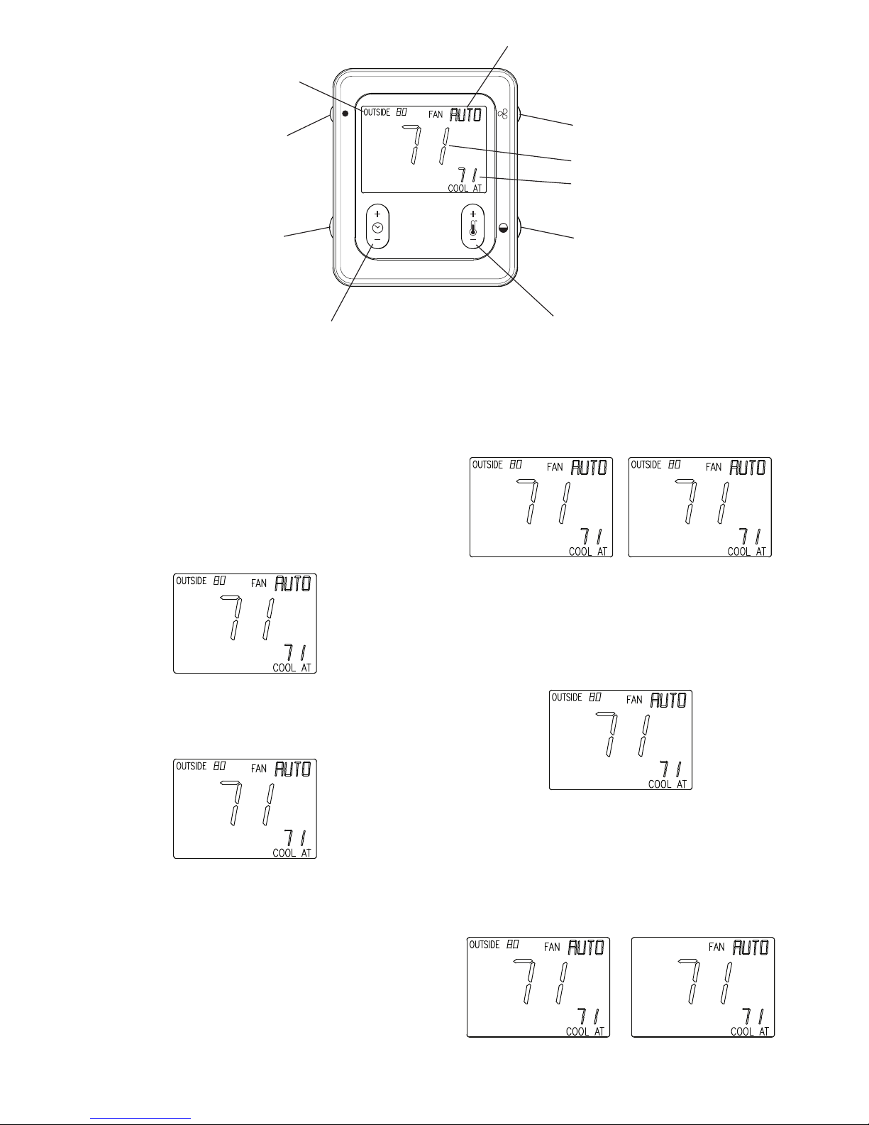
FAN BUTTON
Pressing the FAN button momentarily will scroll through: AUTO,
LOW, MED, and HIGH speed continuous fan operation. The FAN
button is used to enter into the setup mode by holding the FAN
button for 10 seconds.
HUMIDITY/OAT BUTTON
Pressing the HUMIDITY/OAT button will toggle between the
Outside Temperature and Indoor Relative Humidity reading
(humidity reading at wall control). The LCD will revert back to the
outside temperature after 5 seconds.
COOL/HEAT BUTTON
Use the COOL/HEAT button to change between “COOL AT” and
“HEAT AT” setpoints.
TEMPERATURE UP/DOWN BUTTON
Use the TEMP (+/--) button to change a zone temperature setpoint.
Depending on the active heating/cooling mode, the “HEAT AT” or
the “COOL AT” setpoint will appear and will increment or
decrement accordingly. If not in a “HOLD” mode, changing the
setpoint, when used with an Evolution User Interface wall control,
will cause the Override timer to be displayed (i.e. 2--hours). If used
with an Evolution Connex Control wall control, changing the
setpoint will cause a HOLD UNTIL with a default time of
approximately 3 hours from the current time to be displayed. Either
the Override timer or default time can be increased or decreased by
using the TIME (+/--) button.
TIME UP/DOWN BUTTON
When used with Evolution User Interface wall control and the
TIME (+/--) button is pressed during a normal operation,
“OVERRIDE” is displayed and the Override timer is shown
(default is 2--hours). When used with an Evolution Connex
Control wall control and the TIME (+/--) button is pressed during a
normal operation, pressing the setpoint will cause a HOLD UNTIL
with a default time of approximately 3 hours from the current time
to be displayed. When used with either wall control, the Override
timer or default time can be increased or decreased by using the
TIME (+/--) button. While the timer or default time is shown, the
TIME buttons can be used to raise or lower the Override timer or
the default time in 15--minute increments up to a maximum of 24
hours. If the time is decreased to zero, the “OVERRIDE” text
disappears along with the timer or the default time will be replaced
with “SCHEDULED,” depending on the type of wall control, and
the program resumes regular operation.
NOTE: If the wall control is configured for non--programmable
operation, the Evolution Smart Sensor will ignore HOLD and
Override functions at the Smart Sensor.
HOLD BUTTON
Pressing the HOLD button momentarily will cause “HOLD” to be
displayed. The system will continue using the active (displayed)
temperature setpoints indefinitely. Pressing the HOLD button again
removes the “HOLD” text and the system resumes normal
programming schedules. When used with an Evolution User
Interface wall control, pressing the HOLD button for
approximately 3 seconds will cause “UNOCCUPIED” to be
displayed in the lower left area of the LCD and the unoccupied
temperature settings will be displayed. Pressing the HOLD button
again cancels the “UNOCCUPIED” mode and the system resumes
normal programming schedules.
NOTE: The Evolution Connex Control System does not include
an “unoccupied” mode.
SYSTEM OFF
When the OFF mode is selected on the Evolution Connex Control/
Evolution User Interface wall control, the Evolution Smart Sensor
will show “SYSTEM OFF” in the lower left text area of the display
screen. The end user will be unable to operate the system from the
Smart Sensor.
KEYPAD LOCK
The Evolution Smart Sensor can be locked if the FAN and
HUMIDITY/OAT buttons are pressed simultaneously for
approximately 3 seconds. A padlock icon will appear and all push
button functions will be ignored. Pressing the FAN and
HUMIDITY/OAT buttons again for 3 seconds will unlock the
Evolution Smart Sensor.
VACATION
When the VACATION mode is activated from Evolution Control/
Evolution User Interface wall control, the Evolution Smart Sensor
will display the “VACATION” in the lower left area of the LCD.
The padlock icon will appear, flash and ignore all push button
functions for 15 minutes.
ERROR DISPLAY
COM ERROR (Communication Error) will be displayed If the
Evolution Smart Sensor cannot send or receive communication
data with the Evolution Connex Control/ Evolution User Interface
wall control. Check ABCD wiring and Zone address.
SYST ERROR (System Error or Malfunction) will be displayed if
a system critical error is active at the Evolution Connex
Control/Evolution User Interface wall control. Check fault history
at the wall control.