BST iPQ-Spectral User manual

Color
Operating Manual
iPQ-Spectral
Spectral measuring head (C11 SensorUnit)
MD.587.EN.02
with traverse bar ELT-ZA.x, camera unit LVU-CAM-UNIT.x
(option) and motorized backing unit BW-UNIT.x (option)

BST GmbH
Remusweg 1
D-33729 Bielefeld
Tel.: +49 (0) 521 400 70 0
Fax: +49 (0) 5206 999 999
E-Mail: [email protected]
Internet: www.bst.group
This documentation is protected by copyright. The translation as well as reproduction and distribution in any form is forbidden without the approval
of the rights holder and will be pursued under civil and criminal law. Technical modifications reserved.

Table of contents
iPQ-Spectral – Spectral measuring head (C11 SensorUnit) iii
Table of contents
1 About This Document........................................................................................ 5
1.1 What You Need to Know............................................................................................... 5
1.2 Target Group................................................................................................................. 5
1.3 Storage and Distribution............................................................................................... 5
1.4 Meanings of the Safety Instructions and Symbols........................................................ 5
1.4.1 Safety Instructions ........................................................................................................ 5
1.4.2 Symbols......................................................................................................................... 6
1.5 More Detailed Information........................................................................................... 6
2 About Safety ..................................................................................................... 7
2.1 Intended Use................................................................................................................. 7
2.2 Non-intended Use......................................................................................................... 8
2.2.1 Non-intended Infringement of Guidelines.................................................................... 8
2.2.2 Non-intended Operation............................................................................................... 8
2.2.3 Non-intended Modification of Electronic Data............................................................. 8
2.3 Safety Instructions ........................................................................................................ 9
2.3.1 General Safety Instructions........................................................................................... 9
2.4 Qualification of the Personnel .................................................................................... 13
2.5 Duties of the Operating Company and Personnel ...................................................... 14
2.5.1 Duties of the Operating Company .............................................................................. 14
2.5.2 Duties of the Personnel............................................................................................... 15
2.6 Conduct in the Event of Danger and Accidents .......................................................... 15
2.7 Personal Protective Equipment .................................................................................. 16
2.8 Guarantee and Liability............................................................................................... 16
2.8.1 Disclaimer ................................................................................................................... 16
2.8.2 Exceptions to the Disclaimer....................................................................................... 16
2.8.3 License and Liability for Software Supplied ................................................................ 17
3 Technical data..................................................................................................18
3.1 Spectral measuring head ............................................................................................ 18
3.2 Camera unit................................................................................................................. 18
3.3 Backing unit................................................................................................................. 19
4 Measuring head and traverse bar components.................................................20
5 Assembly and commissioning/start-up.............................................................22
5.1 General information ................................................................................................... 22
5.2 Installing the traverse bar........................................................................................... 23
5.3 Requirements.............................................................................................................. 23
5.4 Cable connections....................................................................................................... 24
6 Maintenance and cleaning ...............................................................................25
6.1 Cleaning ...................................................................................................................... 25
6.1.1 Cleaning the protective glass panes............................................................................ 26
6.1.2 Cleaning the tile insert................................................................................................ 26
6.1.3 Cleaning the measuring roller..................................................................................... 27
6.1.4 Cleaning the traverse bar............................................................................................ 27
6.1.5 Cleaning the backing wheel (option) .......................................................................... 27
6.2 Maintenance of the spectral measuring head by BST................................................. 28
6.3 Replacing the backing wheel....................................................................................... 28
6.3.1 Dismantling the backing wheel................................................................................... 29
6.3.2 Installing the backing wheel........................................................................................ 30
7 Installing / dismantling the spectral measuring head........................................32
7.1 Removing the spectral measuring head from the traverse bar .................................. 32
7.1.1 Dismantling the camera unit....................................................................................... 32
7.1.2 Dismantling the spectral measuring head .................................................................. 33

Table of contents
iv iPQ-Spectral – Spectral measuring head (C11 SensorUnit)
7.2 Installing the spectral measuring head on the traverse bar ....................................... 34
7.2.1 Installing the spectral measuring head....................................................................... 34
7.2.2 Installing the camera................................................................................................... 35
8 Replacing the traverse bar motor.....................................................................36
9 Dismantling and disposal .................................................................................38
About This Document 1
iPQ-Spectral – Spectral measuring head (C11 SensorUnit) 5/38
1 About This Document
1.1 What You Need to Know
These instructions help you to work with the system in a safe,
simple and successful manner.
The following instructions must be observed in order to avoid haz-
ards and incorrect operation:
■Every user must have read these instructions in full before
working with or on the system.
■Every user must follow the safety information in these instruc-
tions.
1.2 Target Group
These instructions are directed to all persons that work with or on
the system. The operating company of the entire system and su-
pervising personnel must also be familiar with these instructions.
1.3 Storage and Distribution
These instructions must be stored at the workplace in such a man-
ner that the user has access to them at all times.
These instructions and all other applicable documents are a com-
ponent of the product and must be handed over to the operating
company of the system.
1.4 Meanings of the Safety Instructions and Symbols
1.4.1 Safety Instructions
DANGER
Danger that will lead to death or severe injuries!
►Here you can find how to avoid the danger.
WARNING
Danger that may lead to death or severe injuries!
►Here you can find how to avoid the danger.
CAUTION
Danger that may lead to medium or minor injuries!
►Here you can find how to avoid the danger.
NOTICE
Danger that may lead to damage to assets!
There is no risk of injury.
►Here you can find how to avoid the danger.

1About This Document
6/38 iPQ-Spectral – Spectral measuring head (C11 SensorUnit)
1.4.2 Symbols
Information that is essential for successful operation.
Information that makes operation easier.
Action requirements may include the following symbols:
›› Requirements that must be fulfilled for the action steps.
1. Requirement for you to take actions. And ...
2. …in the sequence specified.
►Requirement for you to take actions - without any certain se-
quence.
1.5 More Detailed Information
►Observe the accompanying documents (e.g. order confirma-
tion) for this system and the operating instructions of the en-
tire system.
The latest version of these instructions can be obtained in all
available languages at:
www.bst.help

About Safety 2
iPQ-Spectral – Spectral measuring head (C11 SensorUnit) 7/38
2 About Safety
The system has been designed according to the state of the art
and fulfils the latest safety standards.
When using the system, risks may occur that could threaten your
life or health or lead to material damage. In order to avoid these
risks, all instructions in this manual concerning safety and all rel-
evant documentation of the entire system must be observed.
2.1 Intended Use
The spectral measuring head, the optional camera and the motor-
driven camera traverse bar are exclusively intended for use on
printing presses. They are designed for absolute color measure-
ment during the printing process. The spectral measuring head,
the camera and the traverse bar may only be operated together
with a BST web monitoring or inspection system.
The system is installed in a machine or assembled together to
form a machine with another machine in compliance with the Ma-
chinery Directive 2006/42/EC. All machines of the entire system
must comply with the guidelines of the Machinery Directive after
being installed in the system.
The system and all of its components are only intended for use in
industrial environments.
The system may only be put into operation if the following
guidelines are also complied with:
■The product must only be installed or operated in a non-ex-
plosive atmosphere.
■The product and all components must only be used in a perfect
technical condition.
■All technical safety equipment must be in a perfect technical
condition.
■The product must only be operated using the components that
belong to the system. An exception are such third party com-
ponents that have been supplied by BST or have been explicitly
approved for being operated with the system.
■Any part found to be working incorrectly must be replaced us-
ing original spare parts immediately.
■All work on or with the product must only be carried out by in-
structed and qualified personnel, see chapter Qualification of
the Personnel, page 13.
■These instructions and all safety information must be observed.
■The operating conditions and performance limits specified in
the technical specifications must be observed.

2About Safety
8/38 iPQ-Spectral – Spectral measuring head (C11 SensorUnit)
2.2 Non-intended Use
Every use is non-intended, that is not described in the chapter In-
tended Use or does not comply with the guidelines specified
there, see Intended Use, page 7.
2.2.1 Non-intended Infringement of Guidelines
■Infringement of operating, maintaining or installation instruc-
tions
■Unsuitable, incorrect or unauthorized use of the product
■Operating the product in an environment not intended for its
use
■Operating the product in breach of the legal safety guidelines
relevant at the location of use
■Neglecting the warning and safety instructions in the relevant
documents for the product
■Operating the product under faulty safety and protective condi-
tions
2.2.2 Non-intended Operation
■Operation by unauthorized or insufficiently qualified personnel
■By-passing, disassembling, switching off or manipulation of
safety equipment
■Incorrect or negligent handling by the customer
■Any intervention, modification or conversions on the product
without the express approval of BST GmbH
■The use of unsuitable operating materials or spare parts
■Operation of the product near to sources of interference, e.g.
electro-magnetic fields (high voltage lines) or sources of heat
■Operation of the product under the influence of chemical, elec-
tro-chemical or electrical factors
2.2.3 Non-intended Modification of Electronic Data
■No virus scanners, firewalls or similar items may be installed on
any products of BST GmbH. Virus scanners or other scan or re-
gistration programs must not (be able to) access products via
networks.
■Writing, deleting and editing of system data / files on BST
products is not permitted. Exempt from this is service work car-
ried out at the instruction of BST GmbH.
■Access of any external software to BST products via networks is
not permitted.
■USB memory sticks may only be used together with BST
products if they are free of viruses and harmful software.
■Products or supplied software from BST GmbH must never be
modified without permission.

About Safety 2
iPQ-Spectral – Spectral measuring head (C11 SensorUnit) 9/38
■All software supplied is protected by copyright and must not be
edited, copied or made available to third parties. Except where
explicit approval has been sought from BST GmbH or the re-
spective owner of the copyright.
2.3 Safety Instructions
Every user must read and follow the safety instructions in these
instructions before working with or on the system.
The following contains general safety instructions that always
have to be observed. Special safety information that must be ob-
served for certain work will be specified at the start of the re-
spective chapter of these instructions.
2.3.1 General Safety Instructions
Assembly and installation Observe the following safety instructions during assembly and
electrical installation of the system.
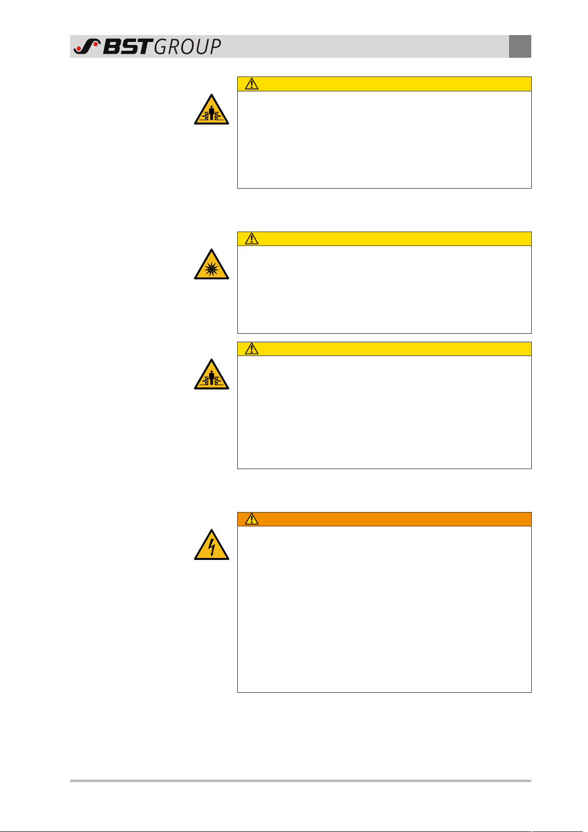
DANGER
The system has no ATEX approval!
Installation of the system in potentially explosive areas can cause
death or life-threatening burns.
►Never install the system in potentially explosive areas.
DANGER
Risk of electrocution caused by increased touch voltage of system
components with damaged insulation!
The PELV circuit may become dangerously active in the event of in-
sulation damage. In this case, touching system components may
lead to severe injuries or even death.
►Route the signal lines (e.g. For the monitor, camera or network)
separately from the mains voltage cables.
WARNING
Danger caused by trapping points between system components
and guide rollers!
Observe the following measures to avoid the danger. Otherwise,
there is a risk of severe injury or even death.
►Install the components of the traverse bar, the drag chain, the
camera unit (except for the front edge of the camera unit), the
spectral measuring head, the motorized backing unit and the
rear flash (some of the components mentioned here are only
part of specific system configurations) at a minimum distance of
120 mm from the nearest guide roller. If you expect to have to
access the space with your entire head or body, select a larger
spacing accordingly.
►Secure the trapping point between the front of the camera unit
and the printed web so that no body parts can enter this hazard
area while the machine is running.
►Work on the camera or traverse bar is only admissible when the
machine is at a standstill.

2About Safety
10/38 iPQ-Spectral – Spectral measuring head (C11 SensorUnit)
WARNING
Danger of crushing during adjustment of the limit switches.
There is a danger of crushing when body parts enter the space
between the camera unit/spectral measuring head and traverse
bar!
►Do not adjust the traverse bar limit switches during system op-
eration.
CAUTION
Danger of crushing caused by the moving slide on the traverse
bar!
If the traverse bar is tilted, the slide can move by itself and cause
crushing injuries.
►Do not remove the transport securing devices on the traverse
bar slide until the machine is completely installed.
CAUTION
Danger of crushing caused by motorized traverse bar!
There is a danger of crushing when body parts enter the space
between the camera unit/spectral measuring head and traverse
bar!
►Connect the voltage supply for the system downstream of a
mains cut-out device according to EN 60204 chapter 5.4
(switch-off device to prevent unexpected start-up).
►When the system is integrated into the printing press, the
owner/user must ensure that the voltage supply of the system
is reliably interrupted once the printing press is switched off or
the EMERGENCY STOP circuit actuated.
CAUTION
Danger of injury caused by poor workplace ergonomics!
Muscle tension, headache and lack of concentration caused by in-
correctly aligned monitors and unfavorable working conditions.
This may result in accidents or chronic disorders.
►Adhere to common, ergonomic design principles for setting up
the workplace.
►Only install monitors, display and operating units at safe and er-
gonomic workplaces with favorable lighting conditions.
CAUTION
The flash tubes of the camera release a low amount of ozone!
Free ozone is harmful to health if it enters the respiratory tracts.
►For this reason, ensure sufficient ventilation of the installation
location of the camera.
About Safety 2
iPQ-Spectral – Spectral measuring head (C11 SensorUnit) 11/38
CAUTION
Danger of crushing caused by pneumatically driven backing wheel
The backing wheel of the motorized backing unit is moved toward
the printed web by means of a pneumatic system. Excessive pres-
sure leads to a risk of injury between the backing wheel and the
printed web.
►Ensure that the pressure reducer connected to the backing unit
is set to 1.8 bar.
Normal operation Observe the following safety instructions during normal operation
of the system.
CAUTION
Blinding due to looking into a bright light source!
Directly looking into bright light sources can lead to impaired vision
and subsequent accidents.
►Never look directly at the light source while it is switched on!
►Take suitable measures (shielding, blocking) to ensure that dir-
ectly looking at the light source is impossible.
CAUTION
Danger of crushing caused by motorized traverse bar!
There is a danger of crushing when body parts enter the space
between the camera unit/spectral measuring head and traverse
bar!
►Prior to starting assembly, maintenance and cleaning work, isol-
ate the system and secure it against being switched on again.
►Ensure that no body parts are within the hazard zone of the tra-
verse bar.
Maintenance, cleaning,
troubleshooting Observe the following safety instructions during maintenance,
cleaning and troubleshooting on the system.
WARNING
Risk of electrocution and damage to the spectral measuring head
caused by unauthorized opening!
Severe injuries caused by live components with up to 1000 V!
Damage to highly sensitive optical / electronic components due to
touching, soiling or vibration.
►Only allow BST service personnel or other authorized personnel
to open, perform maintenance on or repair the spectral meas-
uring head.
►Exercise the greatest possible caution during any work on or
with the spectral measuring head.
►Note the information on safe handling of the spectral measur-
ing head.
2About Safety
12/38 iPQ-Spectral – Spectral measuring head (C11 SensorUnit)
WARNING
Danger of falling caused by motorized traverse bar!
The movement of the traverse bar can knock persons off elevated
locations (e.g. ladders and platforms). This can lead to severe injur-
ies or even death.
►Only clean the camera/the spectral measuring head when the
voltage supply to the machine is switched off or the mains plug
is disconnected.
►Only stay in the vicinity of the traverse bar if you are standing
securely or the system is switched off.
WARNING
Danger of falling and damage to assets caused by stepping/climb-
ing onto components!
Stepping/climbing onto components (e.g. traverse bars or camera
housing) can lead to life-threatening falling accidents and to the
destruction of the components.
►Never climb or step onto components.
CAUTION
Blinding due to looking into a bright light source!
Directly looking into bright light sources can lead to impaired vision
and subsequent accidents.
►Never look directly at the light source while it is switched on!
►Take suitable measures (shielding, blocking) to ensure that dir-
ectly looking at the light source is impossible.
CAUTION
Danger of burns caused by a defective stepping motor!
Touching a defective stepping motor on the traverse bar may lead
to burns.
►Never touch the stepping motor with your naked hands.
Dismantling Observe the following safety information/instructions when dis-
mantling the system.
CAUTION
Danger of crushing caused by the moving slide on the camera tra-
verse bar!
If the traverse bar is tilted, the slide can move by itself and cause
crushing injuries.
►Secure the slide of the traverse bar against moving during dis-
mantling of the system (e.g. with tape).

About Safety 2
iPQ-Spectral – Spectral measuring head (C11 SensorUnit) 13/38
2.4 Qualification of the Personnel
The qualifications required by the personnel are defined as fol-
lows:
Instructed personnel have been instructed comprehensively by
the operating company and informed about the following points:
■Tasks assigned
■Possible hazards when carrying out the tasks
■Possible hazards in the event of incorrect conduct
■Measures for avoiding the hazards
Moreover, qualified personnel have sufficient experience or prac-
tice in the safe implementation of the tasks assigned.
Specialists are in addition in the position to deal with the follow-
ing tasks by themselves due to their training, knowledge and ex-
perience as well as knowledge in the relevant regulations:
■Carrying out the tasks assigned to them
■Recognizing possible hazards
■Undertaking appropriate measures for avoiding the hazards
Specialists must only carry out tasks according to their profes-
sional training.
Qualified electricians have in addition an electrical engineering
training according to the applicable guidelines (in Germany,
DINVDE1000-10).
Moreover, all personnel must satisfy all requirements that are de-
rived from the following documentation or directives:
■Operating instructions for the entire system
■National guidelines, laws and applicable guidelines for protect-
ing employees, general safety at workplaces and for accident
prevention

2About Safety
14/38 iPQ-Spectral – Spectral measuring head (C11 SensorUnit)
2.5 Duties of the Operating Company and Personnel
2.5.1 Duties of the Operating Company
The operating company of the entire system is responsible for
safety in the workplace as well as for the information and training
of the personnel. In particular, for the entire life-cycle of the sys-
tem and the entire system, the operating company must ensure
that:
■All relevant legal safety, accident prevention and environ-
mental guidelines are maintained
■All hazards are determined that result from the special operat-
ing conditions at the operating location of the system and from
the construction of the entire system
■All hazards determined are avoided. This means, in particular:
- Constructive prevention of hazards
- Assembly of protection and safety equipment and checking
that these are working properly
- Mounting of warning signs at hazard sites and checking their
correct condition
- Information and training of the personnel for safe conduct,
intended use, safety equipment, prevention of hazards and
conduct in the event of emergencies
- Provision of the necessary personal protective equipment
- Supervision of the personnel with regard to safety-relevant
conduct
■The system is integrated into the safety concept of the entire
system
■The system is stopped immediately if the safety of people or
the environment is endangered or changes occur that could im-
pair the safety
■All employees have read and understood these instructions be-
fore working on or with the system
■Only personnel are assigned that are qualified and trained for
the respective task
■The responsibility of the personnel is determined for the task
to be completed and that the personnel are informed

About Safety 2
iPQ-Spectral – Spectral measuring head (C11 SensorUnit) 15/38
2.5.2 Duties of the Personnel
Each and every employee is responsible for their own safety. In
particular, each and every employee must abide by the following
instructions:
►Read these instructions completely before working on or with
the system and follow all safety instructions.
►Observe all warning instructions on the system and entire sys-
tem.
►Observe the operating instructions for the entire system and
the separate machines as well as all safety instructions included
in it.
►If required, wear the necessary personal protective equipment.
►Before starting work, check if the safety equipment is intact.
►Stop the system immediately if the safety of people is at risk
and secure against being switched back on unintentionally.
►The system must be visually inspected for any recognizable
damage or problems at least once per shift.
►If sections of these instructions are unclear, inform your super-
visor and ensure for clarification.
2.6 Conduct in the Event of Danger and Accidents
Preventative Measures
Emergency and rescue equipment must be ready for use in every
company. These include, for example, emergency stop buttons,
fire extinguisher, first aid kit and equipment for reporting acci-
dents.
►Always be prepared for emergencies, accidents and fire.
►Familiarize yourself as to where the emergency and rescue
equipment is located and how to use it.
►Keep emergency and rescue equipment at hand and ready for
use.
►Ensure all access routes for rescue vehicles and escape routes
are kept free.
If an emergency is impending or has occurred
1. Press the emergency stop button immediately.
2. Make sure that the system cannot be switched on again.
3. Rescue the persons from the danger zone if your personal
safety is not at risk.
4. Initiate first aid measures.
5. Warn the emergency doctor and / or fire brigade.
6. Inform the responsible person at the operating location.
7. Clear the access route for the emergency vehicles.

2About Safety
16/38 iPQ-Spectral – Spectral measuring head (C11 SensorUnit)
2.7 Personal Protective Equipment
When carrying out certain activities, you have to wear personal
protective equipment in order to avoid accidents and injuries. Per-
sonal protective equipment includes, depending on the activity:
■Protective clothing
■Safety helmet
■Safety shoes
■Safety gloves
■Eye protectors
■Ear protectors
►Observe the safety information in these instructions and the in-
formation signs on the system for personal protective equip-
ment.
2.8 Guarantee and Liability
The warranty terms are specified in the sales documentation.
2.8.1 Disclaimer
BST GmbH is not liable for damage or defects arising from any in-
correct or non-intended use of the product, see Non-intended
Use, page 8.
Liability for defects does also not apply if the fault originates from
one or more of the following causes:
■Catastrophic events and force majeure
■Natural wear
■Incorrect operation of the product resulting from the effect of
connected or neighboring third party devices
■Malfunction of the product due to unsuitable operating re-
sources, spare parts, chemical, electro-chemical or electrical
factors.
■Unsuitable or faulty execution of the maintenance work de-
scribed by the operating company, see Maintenance and Clean-
ing.
2.8.2 Exceptions to the Disclaimer
In the cases listed above BST GmbH shall also not be liable (for
damages) unless:
■The damage results from a willful or grossly negligent breach of
duty on the part of BST GmbH or its legal representatives or vi-
carious agents
■The damage is associated with injury to life, body or health and
results from a willful or grossly negligent breach of duty on the
part of BST GmbH or its legal representatives or vicarious
agents

About Safety 2
iPQ-Spectral – Spectral measuring head (C11 SensorUnit) 17/38
■The form of damage can usually and typically be insured
against by means of third-party liability insurance taken out by
BST GmbH on reasonable conditions
This applies in particular to claims for damages associated with
fault or negligence occurring before or upon conclusion of the
contract, the infringement of secondary obligations and claims as-
sociated with impermissible actions; this does not affect claims as-
serted in accordance with the German Product Liability Act or
those associated with a guarantee.
Otherwise, the specific terms of license of BST GmbH apply.
2.8.3 License and Liability for Software Supplied
Software supplied that has not been produced by BST GmbH un-
derlies the respective liability and license agreements of the man-
ufacturer.

3Technical data
18/38 iPQ-Spectral – Spectral measuring head (C11 SensorUnit)
3 Technical data
Overview The following technical data applies to the iPQ-Spectral spectral
measuring head.
3.1 Spectral measuring head
Described object Types
Spectral measuring head C11 SensorUnit
Measurement Supply
Spectral measuring range 380 nm to 730 nm
Measuring geometry 45°x:0°
Measuring condition M2 acc. to ISO 13655:2009
Output 10 nm resolution
Electrical technical data Supply
Rated voltage 24V DC
Rated current 2 A (+/- 5%)
Overvoltage category II
Mechanical technical data Dimensions, weight, fastening
Dimensions (W x H x D) 250 x 200 x 205 mm (with con-
nections)
Weight 8 kg
Fastening
Fastening on the sensor console
of the traverse bar using 4x M6
screws
Environment
Operating temperature 10 ... 40 °C
Ambient temperature - 20 ... 60 °C
Air humidity (relative) 10 ... 90 %, no condensation
Protection type IP54
3.2 Camera unit
Described object Types
Spectral measuring head LVU-CAM-UNIT.0-x
Electrical technical data Supply
Rated voltage 24V DC
Rated current 800 mA (+/- 5%)
Overvoltage category II

Technical data 3
iPQ-Spectral – Spectral measuring head (C11 SensorUnit) 19/38
Mechanical technical data Dimensions, weight, fastening
Dimensions (W x H x D) 250 x 200 x 195 mm (with con-
nections)
Weight 5.4 kg
Fastening
Fastening on the sensor console
of the traverse bar using 4x M6
screws
Environment
Operating temperature 10 ... 40 °C
Ambient temperature - 20 ... 60 °C
Air humidity (relative) 10 ... 90 %, no condensation
Protection type IP20
3.3 Backing unit
Described object Types
Backing unit BW-UNIT.0
Electrical technical data Supply
Rated voltage 24V DC
Rated current 1.5 A (+/- 5%)
Overvoltage category II
Fuse 3AT required (external)
Compressed air Supply
Pressure 1.8 bar (ensured by supplied
pressure reducer)
Connection 8 mm push-pull
Mechanical technical data Dimensions, weight, fastening
Dimensions (W x H x D) 255 x 266 x 270 mm (with con-
nections)
Weight 13 kg
Fastening
Fastening on the fastening plate
of the traverse bar using 4x M6
screws
Environment
Operating temperature 10 ... 40 °C
Ambient temperature - 20 ... 60 °C
Air humidity (relative) 10 ... 90 %, no condensation
Protection type IP20
4Measuring head and traverse bar components
20/38 iPQ-Spectral – Spectral measuring head (C11 SensorUnit)
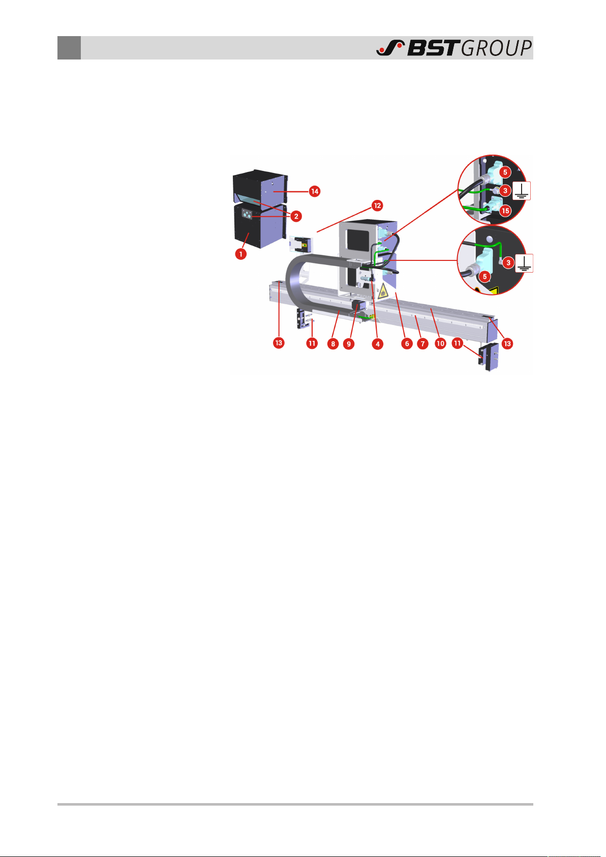
4 Measuring head and traverse bar components
Overview The following figure shows the mechanical components and the
electrical connections of the measuring head, the optional camera
unit and the motorized traverse bar.
Components and connections
①Housing of the spectral measuring head
②Lenses
③Functional grounding connection (threaded bolt)
④Connection for motor cable (X2)
⑤Connection for signal cable (X1, CAN bus connection and 24
V voltage supply)
⑥Sensor console with tilt adjustment
⑦Motorized traverse bar
⑧Drag chain for cable guidance
⑨Traverse bar motor
⑩Rack
⑪Alignment tool for horizontal and vertical fine adjustment
⑫Calibrating unit with tile insert
⑬Limit stop
⑭Camera unit (option)
⑮Connection for image data cable (X2, Ethernet connection)
Either a coated measuring roller or a motorized backing unit with
backing wheel is supplied for backing the printed web. The follow-
ing figure shows the mechanical components and the electrical
connections of the motorized backing unit.
Table of contents
Other BST Industrial Equipment manuals

Popular Industrial Equipment manuals by other brands

Lintec
Lintec LC-3000L Series instruction manual

IMMO
IMMO EFI PGR02 Short user manual

Clenergy
Clenergy PV-ezRack Code-Compliant Planning and Installation Guide

OHAUS
OHAUS DEFENDER SERIES instruction manual

ABB
ABB HT845196 Operation manual

Suzohapp
Suzohapp Comestero Mifare Cashless systems Technical document - User instruction


Vaisala
Vaisala TacMet MAWS201M Spare Part Guide

BAC
BAC PCT Cooling Tower Rigging & Assembly Instructions

SMC Networks
SMC Networks AW20 Series Operational manual

Van Beest
Van Beest Green Pin Tycan Lashing Chain user manual

LNS
LNS Hydrobar Express 332 Troubleshooting and Spare Parts Manual

ABB
ABB HT562788 Operation manual