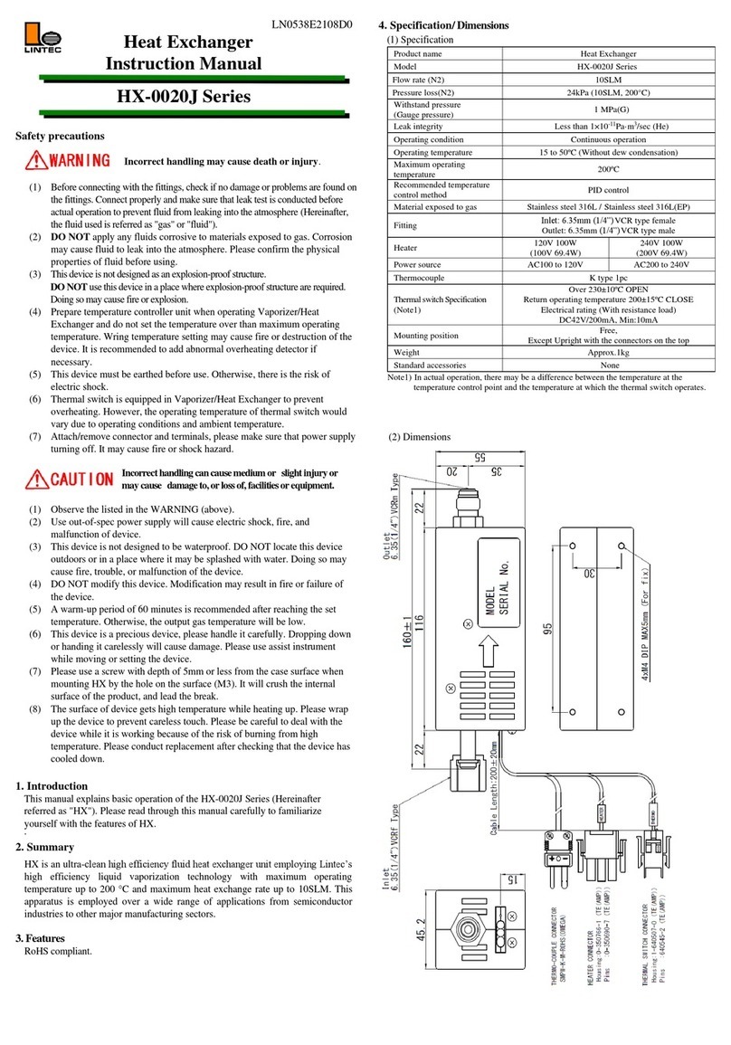
Lintec LC-3000L Series User manual

LN0371E2109C0
Liquid Mass Flow Controller
Instruction Manual
LC-3000L Series
Safetyprecautions
Incorrecthandling maycausedeathorinjury.
(1) Before connecting the fittings, check that no damage or defects are found on
the fittings. Make connect properly and make sure that leak test is conducted
before actual operation to prevent fluid from leaking into the atmosphere
(Hereafter, the measured fluid is called “liquid” or “fluid”).
(2) DONOTapply any fluids corrosive to the wetted materials. Corrosionmay cause
fluidtoleak into theatmosphere.Check theliquid type to be used in advance.
(3) Thedevice isnotdesigned asanexplosion-proofstructure.DO NOTuse device in a
where explosion-proof structures are required. Doingso may cause fire or explosion.
Incorrecthandlingmayleadto medium orslightinjuryormay
causedamage to,or loss of,facilities or equipment.
(1) Observetheprecautionslistedinthe WARNING (above)
(2) Strictly observe the electrical specifications. Not doingso cause fire, damage to
sensorsormalfunction.
(3) Thisdeviceisnot designed tobewaterproof.DONOTlocate thisdevice outdoors or
in a place whereit may be splashed with water. Doing so may cause fire, trouble or
malfunctionofthisdevice.
(4) DONOT modifythisdevice. It maycause fire or other problems.
(5) While a power supply is applied to the device, +15VDC and -15VDC must be
applied simultaneously. If only +15VDC or -15VDC is applied, electronic
circuits will become unstable and it may cause a malfunction.
(6) This device is not designed to handle hot swap. Please avoid attaching and
removing the power supply connector and interface connector with the power
switched on. Attachment and/or removal with the power on may result in
failure of the device.
(7) This device is a precious device,pleasehandle it carefully. Dropping down or
handlingitcarelessly will cause damage. Please use assist instrument whilemoving
orsettingthe device.
(8) Regularmaintenance is recommended for continuous useofthisdevice
(Recommended frequency is once ayear).
1.Introduction
Thismanual explains basicoperation ofthe Liquid Mass FlowController LC-3000L
Series (Hereafter, it iscalled "LC").
Please read through this manual and the separate volume “The Digital Interface Manual”
carefullyto become familiar with the featuresof this device.
2.Summary
The LC is high performance mass flow controller for gas using thermal
flow sensor and high response piezoelectric valve.
3.Features
The LM has the following features.
(1) LINTEC’s original ambient temperature compensation mass flow sensor is
incorporated for measuring flow rates.
·Low sensortemperature, long-time steady monitor, andfew problems such as
degradation ofgas to be monitored.
·The effect ofambient temperature is less because the sensor temperature is keptat
theambienttemperature.
·Steady temperature distributionofsensorand high-speed response.
(2) Digital controlby microprocessor and high-resolution A/D, D/A converter;
·High functionality
·By settingof device number (address), multiple devices canbecontrolledthrough
a single interface
·Many added functionssuch as flowtotalizer, auto-zero , and ramping functionetc.
(3) Universaldigitalinterface
(4) Superiorcorrosion resistant sealing materialsmake maintenance easy.
Metalseals (StainlessSteel 316L) are used
(5) Particle free structure
(6) By using a metal case andvarioustypes offilters, steady operation canbe achieved
even in anenvironment of high-frequency noise andstationary magnetic field
(7) RoHScompliant
(8) Bypass-less construction (Easy liquid feed and internal purging. mounting
direction: free)
4. Specification/Dimensions
(1) Specification
Product name
Liquid Mass Flow Controller
Model
LC-3102L
LC-3202L
Precursor type and Fluid & flow
rate (except HCl, HF and other
liquidswhichcorrodestainlesssteel)
C2H5OH 0.1 to 1.0g/min F.S.
H2O 0.1 to 0.2 g/min F.S.
C2H5OH 1.0 to 2.0g/min F.S.
H2O 0.2 to 0.4 g/min F.S.
Operation of external valve
Piezo actuator / Normally Open
Surface treatment
NO: No treatment (no surface treatment)
MO: Precision polishing
Minimum control flow rate
5% F.S.
Analog flow rate setting signal
0 to 5VDC (Proportional to flow rate)
Analog flow rate output signal
0 to 5VDC (Proportional to flow rate)
Accuracy (Note1)
±1.0 %F.S.
Repeatability (Note1)
±0.5 %F.S.
Operating differential pressure
(Note1)
50 to 300 kPa(D)
Maximum operating pressure
(Note1)
300 kPa(G)
Pressure Limit
1MPa(G)
Operating temperature & Humidity
(Note2)
15 to 35°C· 0 to 80%RH
(Dewing should be avoided)
20 to 30°C· 0 to 80%RH
(Dewing should be avoided)
Temp. coefficient
(Note2)
(Reference Temp.25)
Zero
±
0.1 %F.S./
℃
Span
Leak integrity
Less than 1×10-11 Pa·m3/sec (He)
Recommended gas for pushing
the liquid (Note3)
He
Storage temperature& Humidity
0 to 60 °C
·
0 to 80 %RH (Condensation should be avoided)
Mounting direction
Free
Wetted materials
Stainless Steel 316L,
PCTFE
Stainless Steel 316L,
PFA, Ni-Co
Seal materials
Au
Fittings
3.2mmVCR(male), 6.35mmVCR(male), 3.2mmSWL
Digital interface connector
RS-485 (RJ45 modular jack) 2-wire system
Power supply
+15VDC±3% 100mA, -15VDC±3% 50mA
Inrush current
(Actual measurement value)
+15V: 11A 130 µs -15V: 9A 110 µs
Analog interface connector
D-sub connector (Fixed size of screw M3)
Weights
Approx.1kg
Note1)Whenusingasa liquidcontrollerforvaporizationsystem, please refertothespecification
sheetof vaporizationsystem.
Note2)Theflowrate willbenot accurateiftheliquidtemperature isdifferent fromsurrounding
temperaturewhen measuring or controlling, please setthesametemperature forliquidandthe
device.
Note 3)There is the possibilityoffailureabout measuringandcontrolling.Toreduce thegassolubilityof
theliquid, Helium(He)is recommendedtobe thepressurizedgas.
· Connectthe LCtothe frame ground.
· Flowratecalibrationis done byC2H5OH or H2O.
· Liquid with solid materials can’t be controlled.
· Ifthemixture ratioofmixture liquid ischanged,pleaseconsultus inadvance.
· Ifthereare particlesinthe target liquid,installafilterto remove particles more than 0.2μm on the
primaryside(theinletside).
· The viscosityofliquid controlledby theLCshould be less than 0.1Pa·s (100cp). Pleaseconsultusif
the viscosityofliquidishigh.
· Pleasefeedin the liquidafter completely purging(Recommended).
(2) Dimensions
3.2mm VCR (male) 112mm specification

5. Ordering Information
LC - 3*02L -MO -22 VR1 JA0A0
[1] [2] [3] [4] [5] [6]
[1]SeriesModel LC: Liquid Mass Flow Controller LC Series
* Dependsonthe flow rate
[2] Seal type (Surface treatment)
NO: No treatment
MO: Precision polishing treatment
[3]INLET,OUTLET fitting size (IN side,OUT side)
E.g. if: 3.2mm, OUT:3.2mm, label as [22] 2 indicates size is 3.2mm
[4]Fittingtype
VR1: VCR-compatible 112mm SWL: SWL127.4mm
* Dependsonthe fittingsize
[5] Option J: 2%Close (This option “J”isrecommended)
[6] Other options
Non-option setting is labeled “AA0A0”, please consult for more information.
6. Connection
(1) Analog interface connector
Mounted connector :D-Sub 9pin (male) Pair connector :D-Sub 9pin (female)
(Fixed size of screw M3)
Pin No.
Signal Name
Function
1
Valveoverrideopen/closesignal
(Note 4)
+15VDC:Open, -15VDC:Close
2
Flow rate output signal 0 to 5 VDC
Flow rate of power output (plus side)
0 to 5 VDC
3
Power supply +15VDC±3%
Power supply (plus) (100mA)
4
Power supply COMMON
(Note 5)
Power supply COMMON ±15VDC
5
Power supply -15VDC±3%
Power supply (minus) (50mA)
6
Flow rate setting signal
0 to 5 VDC
Flow rate of power input (plus side)
0 to 5VDC
7
Flowrate outputCOMMON(Note5)
Flow rate output signal COMMON
8
Flowrate settingCOMMON(Note5)
Flow rate setting signal COMMON
9
N.C.
-
Note4) Theimpedanceofthe input setting offlow rate voltage is 100kΩ, the resistanceofvalveopen
andcloseis 100kΩ.
Note5) PinNo. 4,7,8areconnectedinthisdevice.
Toavoidtheeffect ofCOMMONpotentialdifference, pleasefollowthecircuitasbelow.
If the high accuracy of the control is necessary, setting flow rate voltage is COMMON
(Pin.8), and the flow rate output is COMMON (Pin.7) on the power side. Please do not
connect the power COMMON (Pin4).
(2) Digital interface connector
Mounted connector: RJ45 modular jack Pair connector: RJ45 modular plug
Pin No.
Name
Function
1
Signal COMMON
RS-485 Signal COMMON
2
Signal COMMON
RS-485 Signal COMMON
3
N.C.
-
4
Signal [-Txd/Rxd]
RS-485 2 -wire system transmitter.
receiver minus signal
5
Signal [+Txd/Rxd]
RS-485 2- wire system transmitter.
receiver plus signal
6
N.C.
-
7
N.C.
-
8
N.C.
-
7. Alarm function
This LC features two alarm modes: alarm A and alarm B. Using a digital interface,
alarm output of the digital connector or LED indicator located on top of the LC can
monitorthe alarm status. Alarm setting can only be changed through digital
communication, so if a change is required, please do it through communication.
Details are described in the digital interface manual and others.
Alarm
Set off
LED indicator
A
Setting value ≠ Flow rate output
Continuous Red
Flow totalizer Alarm level 2
Powersupplyvoltagedrop(+15VDC)
Off
B
Valve voltage offset (At controllers)
Red (every 0.5sec flashing)
Zero adjustment error (Note6)
Flow totalizer Alarm level 1
Other
Command error
Continuous Red (every 0.5sec flashing)
Normal
-
Green (every 1sec flashing)
8. Initial setting value (factory shipped value)
This device is provided with a software switch for operation mode setting. Before
operation, input the necessary data for various functions by using the digital
interface. Details of the functions are described in the digital interface manual etc.
Software switch
Available values
Function
Default
Device number
00 to 99
LC No. Registration
00
Alarm A range
1 to 99 [%]
Setting Alarm A range
5%
Alarm B range
1 to 99 [%]
Setting of Alarm B range
20%
Alarm timer
0 to 99 [seconds]
Setting of time to prohibit Alarm
5seconds
Alarm A output
Enable / Disable
Setting ofAlarm A LED display
Enable
Alarm B output
Enable / Disable
Setting of Alarm B LED display
Disable
(Note 6)
Operation mode
Analog / Digital
Switching of Analog/digital
Analog
Power on mode
Analog / Preset
Switching of Operation mode in
power turning on
Preset
Valve control
C / O / H / S
Close / Open / Hold / Servo
Servo
Control speed
FAST / SLOW
Switching of Response speed
FAST
Control mode
(Note 7)
2%Close/2%Hold/Normal
Control mode setting at flow rate setting<2%.
2%Close: Valve Close
2%Hold: 2% Control
Normal: Normal Control
2%Close
Communication
protocol
9600 to 38400bps
8bit / 7bit
Odd/Even/ None
1bit / 2bit
Baud rate
Character length
Parity
Stop bit
9600bps
7bit
None
2bit
Note6)Zero adjustment error alarms regardless of the “Enable” / “Disable” of the alarm.
Note7)Thistableisthe settingwhen less than 2% Closesetting"JA0A0" isspecified.
· If the zero adjust button on the top of the device is pressed and held for over 5 seconds,
the communication protocol is reset to default value (factory shipped value).
9. Operation
(1) Preparation, operation
1) This product is packedin aclean room before shipment. Please break the seals in a
clean room after taking it out of its box.
2) Checktheliquidtypeand flowrate,and check the directionofthe gasflowandthe
MFC before installation.
3) Check forgas leaks from thetubing with ahelium(He)leak detector.
4) Connect the interface connectorsaccording to theConnector table.
5) Powerrequirementsare+15VDC:100mAand-15VDC:50mA.
Checkthevoltage,polarity andcapacitanceofthepower supplyvoltage.
6) Turn on the power supply and let the equipment warm up for at least 5
minutes (Recommended time: 30min).
7) Adjust thezeropoint by pressing thezero-adjustment switch located on the top of
the LC. Before zero adjustment, check that liquid is not being suppliedand
the device was warmed up for 30 minutes or more in order to ensure sensor
stability.
8) Inputtheflowratesettingsignalandsupplygaswithrequireddifferentialpressuretothe
LC. The LCwillbeginto controltheliquid flowinproportionto the presetvoltage.
Full-scalevoltageis5VDC.Maximum input voltage is ±15.5VDC.
9) When the output flow rate signal is used, the tolerance voltage of the external
device shouldbemorethan±15.5VDC.When thepower issupplied,there isthe
possibility to achieve the maximum voltage in the range of ±15.5VDC.
10)When a highly reactive liquid is used, thoroughly purge all foreignmatter from
the tubing and the LC before operation.
11)When contaminated liquid is used, install a filter at the equipment inlet.
12)Use the LC within the range of the operating temperature, and keep it at the
same temperature with the gas. If used
inany environmentthat does not meet the above-mentioned requirements,
the flow rate cannot be measured accurately and the device may fail.
13)Do not switch the power supply on and off within one second. It may cause
failure.
14)Helium(He)gas is recommended for pushingthe liquid. If anyother gas is used,
thedissolvedgas will produce bubbles, and it may make the controlunstable.
15)Bubbles may become the cause oftheunstablecontrol. So, perform the vacuuming
of liquid line thoroughly before the introductionofliquid(Recommended).
(2) Usage ofthe digital interface
This unit supports RS-485 interface. Therefore, with the use of the digital
interface, high performance liquid mass flow control can be achieved. Please
refer to the digital interface manual.
10. Product warranty
(1) Period
This product is guaranteed for a period of 1 year from the date of
shipment. Defects are repaired according to the following regulations.
(2) Scope
Warranty coverage is restricted to this product only. Any other damage
caused by this product is not covered.
(3) Disclaimer facts
The following repairs are not covered by the warranty.
1) Failure caused by by-product of liquid or gas used
2) Failurecausedbymisuse(includingcarelessoperation)or incorrectrepairormodification
3) Failure caused by falling or dropping after purchase
4) Failure caused by fire, earthquake, flood, lightning or other naturaldisasters
Even if the warranty period is still in effect, repair service may not be provided
in the following cases.
1) When the kind of liquid or gas used in the product is unclear
2) The product is returned with liquid or gas remaining inside and safety cannot
be confirmed
Please be aware that this device is a precision instrument and the generation
of excessive electrical noise, changes in liquid temperature or pressure
fluctuations may result in unstable control.
This instruction manual is subject to revision without notice.
http://www.lintec-mfc.co.jp
CorporateHeadquarters
4-1-23 Sekinotsu, OtsuCity,ShigaPref.520-2277,Japan
TEL. +81-(0)77-536-2210FAX.+81-(0)77-536-2215
TokyoBranchOffice
3FHattoriBuild.,4-30-14YotsuyaShinjyuku-kuTokyo 160-0004, Japan
TEL. +81-(0)3-5366-2801FAX.+81-(0)3-3341-3513
This manual suits for next models
2
Other Lintec Industrial Equipment manuals
Popular Industrial Equipment manuals by other brands
Nakanishi
Nakanishi AL-M1202 Operation manual
Novexx Solutions
Novexx Solutions EIDOS XTO Series user manual
Tetratec Instruments
Tetratec Instruments LFE-LDS Operation manual
Lillbacka Powerco
Lillbacka Powerco Finn-power P51MS manual
Kongskilde
Kongskilde ITF 80 manual
Siemens
Siemens SICAM A8000 Series quick start guide

