BTI DKB 2200 SE User manual

!"# $%&'%()#*!#!+",'-!.&!#)*#'+.#/),0#
$.".,!*'"".,)#/),#1%,."%",!1)#+"%-!.&%,!%
)& +%2)"3#%&*#'+),#$%&'%(#2.,0
+"%"!.&%,3#1.,)#*,!((#$.".,
*) +!14),4)!"+5#'&*#6)",!)6+%&()!"'&7#28,0
+"%"!.&9,)#:),&6.4,$.".,)#28,#2)+"%&6%'
/" &.,$%+#*)#+)7',%&;%#)#&.,$%+#*)#'"!(!-%;<.0
$.".,#*%#6,.1%#*)#/),2',%;<.
)+ $%&'%(#*)#'+'%,!.#3#*)#+)7',!*%*#/%,%0
$.".,#*)#"%(%*,.#1!(=&*,!1.#2!>.
2, $%&')(#*)#+?1',!"?#)"#*@'"!(!+%"!.&#/.',0
$.".,)*'1")',+#/.',#$%14!&)+#%#2.,),#)()1",!A')+
*% +!::),4)*+5#.7#6,'7),$%&'%(#2.,0
+"%"!.&B,#:),&)6.,)$.".,
&( C)!(!74)!*+5#))6,'!:+C..,+14,!2")&#C..,0
C%+")#:(.:6..,
)(#

! " #
!!
$

%
&
'
(
'(
%
&
)
*

+,
-.$
/
0
-.)
1
2

3
4
5
6
7
8
9
:
;
< =
>

6+;1&4?@
6+;1&4?@
A

-B$?C?=BD
=B$?C?$DBD
$<B$?C?))BD 22<
$D

$$
"#$
!"#$!
"%&
'(((
)*((
)+((
),((
)'((
)(((
*((
+((
,((
'((
(
( )(( '(( -(( ,(( .(( +(( /(( *(( 0(( )(((

1 Italiano
!
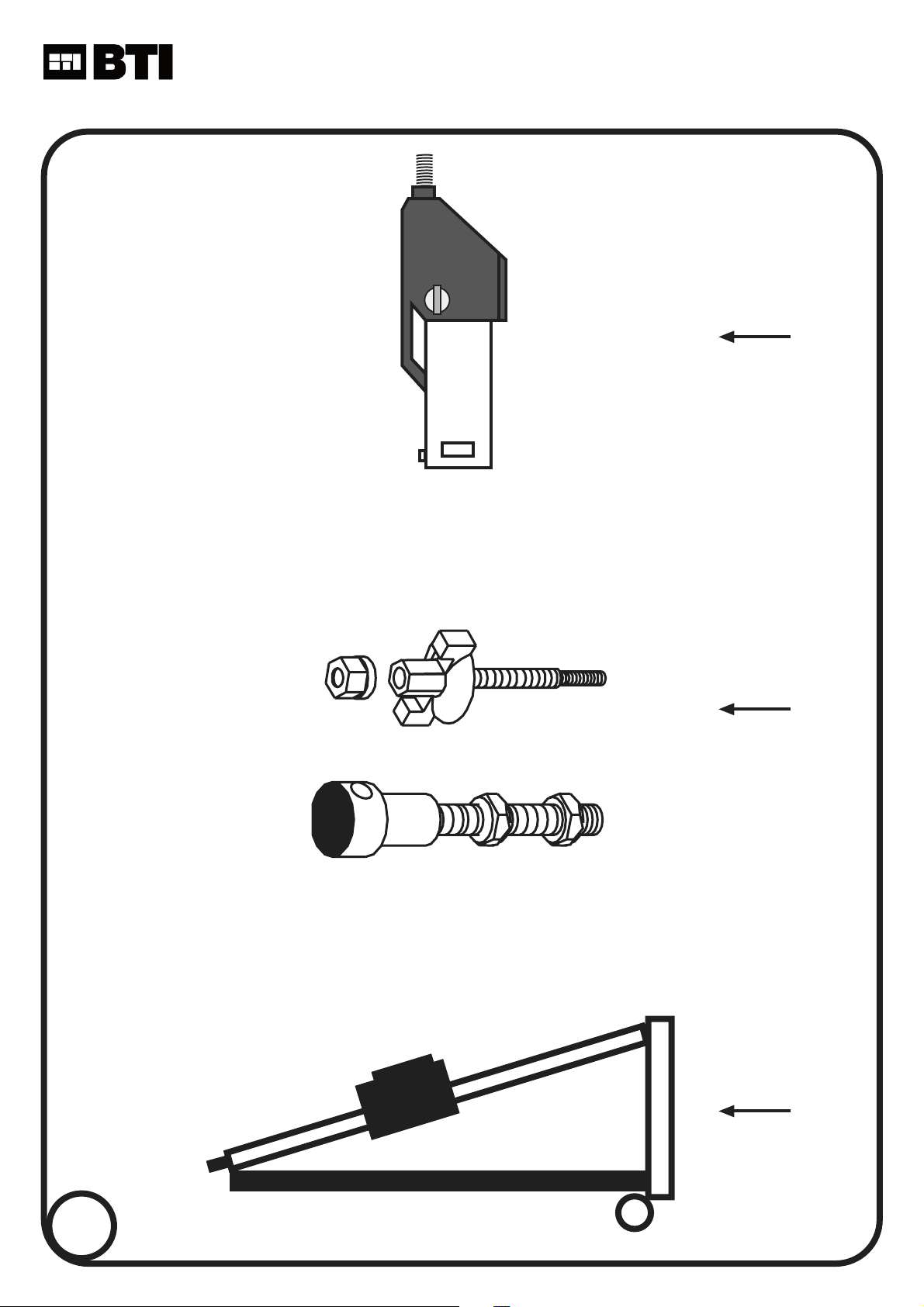
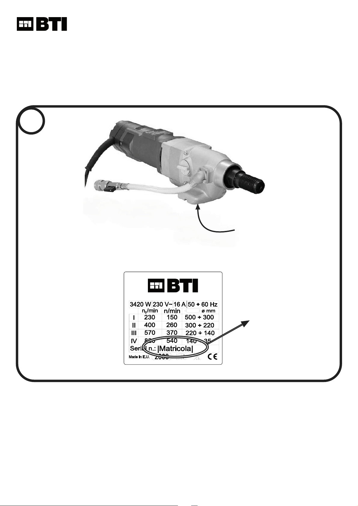
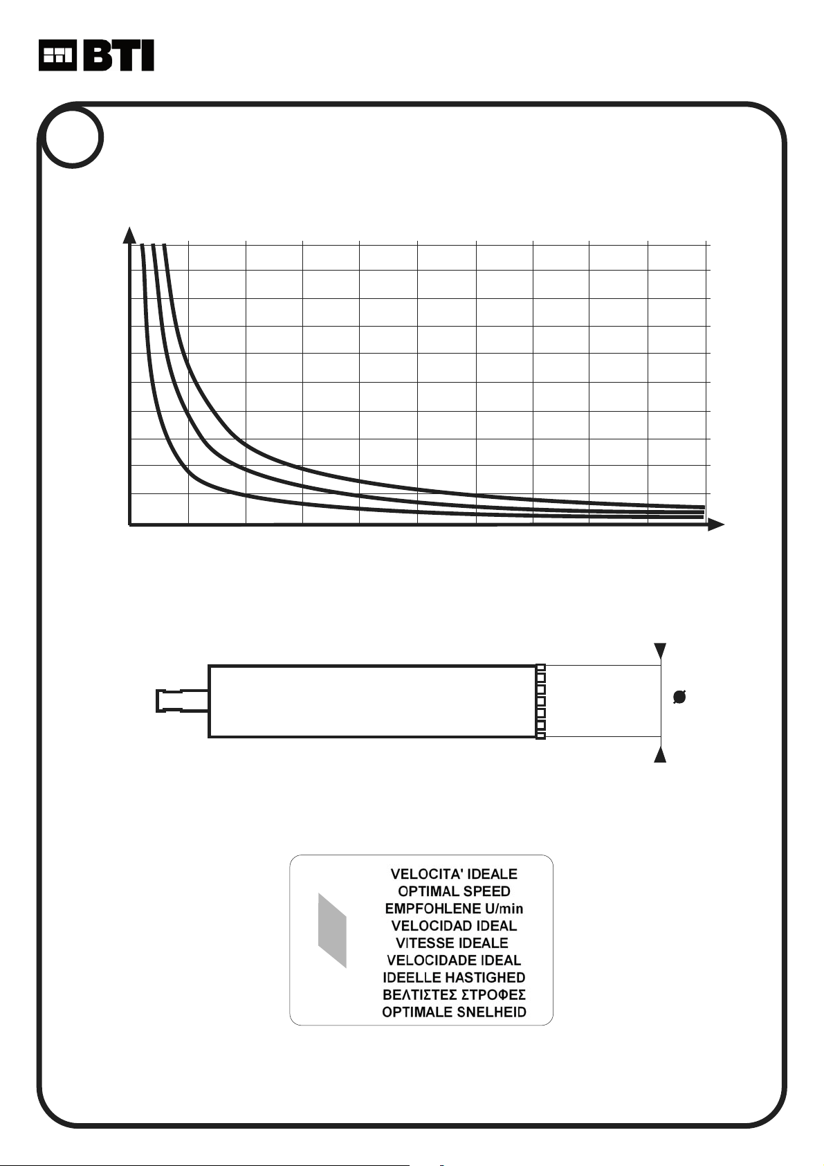
Il vostro motoriduttore BTI (figura 1, Z) è un utensile elettrico che deve essere utilizzato
montato su un adeguato supporto (X) a sua volta fissato con un adeguato sistema di
ancoraggio (Y). Questi tre elementi formano una carotatrice (X+Y+Z), adatta all’esecuzione di
fori su materiali lapidei (es.: mattoni, muratura, pietra naturale, calcestruzzo armato e non)
utilizzando una corona diamantata.
Il motoriduttore rispetta le normative vigenti. Affinché la carotatrice sia a norma, anche il
supporto e il sistema di ancoraggio devono rispettare le relative normative.
N
No
or
rm
me
e
d
di
i
s
si
ic
cu
ur
re
ez
zz
za
a
g
ge
en
ne
er
ra
al
le
e
ATTENZIONE! Leggere tutte le istruzioni. La mancata
ottemperanza a tutte le istruzioni sotto elencate può dare
luogo a scosse elettriche, incendi e/o lesioni serie. Il termine
"utensile elettrico" di tutte le avvertenze elencate qui sotto si
riferisce agli utensili elettrici azionati mediante collegamento
alla rete (con cavo) o azionati a batteria (senza cavo).
CONSERVARE QUESTE ISTRUZIONI
1) Area di lavoro
a) Tenere pulita e ben illuminata l'area di lavoro.
Le aree ingombre e buie possono provocare
incidenti.
b) Non azionare utensili elettrici in atmosfere
esplosive, ad esempio in presenza di liquidi,
gas o polveri infiammabili. Gli utensili elettrici
creano scintille che possono provocare
l'accensione di polveri o fumi.
c) Tenere i bambini e i passanti ad adeguata
distanza durante l’azionamento di un utensile
elettrico. Le distrazioni possono far perdere il
controllo dell'utensile.
2) Sicurezza elettrica
a) La spina dell'utensile elettrico deve
corrispondere alla presa. Mai modificare la
spina in alcun modo. Non utilizzare spine
adattatrici con utensili elettrici dotati di messa a
terra (a massa). Spine non modificate e prese
corrispondenti riducono il rischio di scossa elettrica.
b) Evitare il contatto del corpo con superfici
messe a terra o a massa quali tubi, radiatori,
cucine e frigoriferi. Se il corpo è a terra o a
massa, il rischio di scossa elettrica aumenta.
c) Non esporre gli utensili elettrici alla pioggia e
non utilizzarli in luoghi umidi. L'ingresso di
acqua in un utensile elettrico aumenta il rischio di
scossa elettrica.
d) Non maltrattare il cavo. Non utilizzare mai il
cavo per trasportare, tirare o scollegare dalla
presa di rete l'utensile elettrico. Tenere il cavo
distante da calore, olio, bordi affilati o parti in
movimento. Cavi danneggiati o attorcigliati
aumentano il rischio di scossa elettrica.
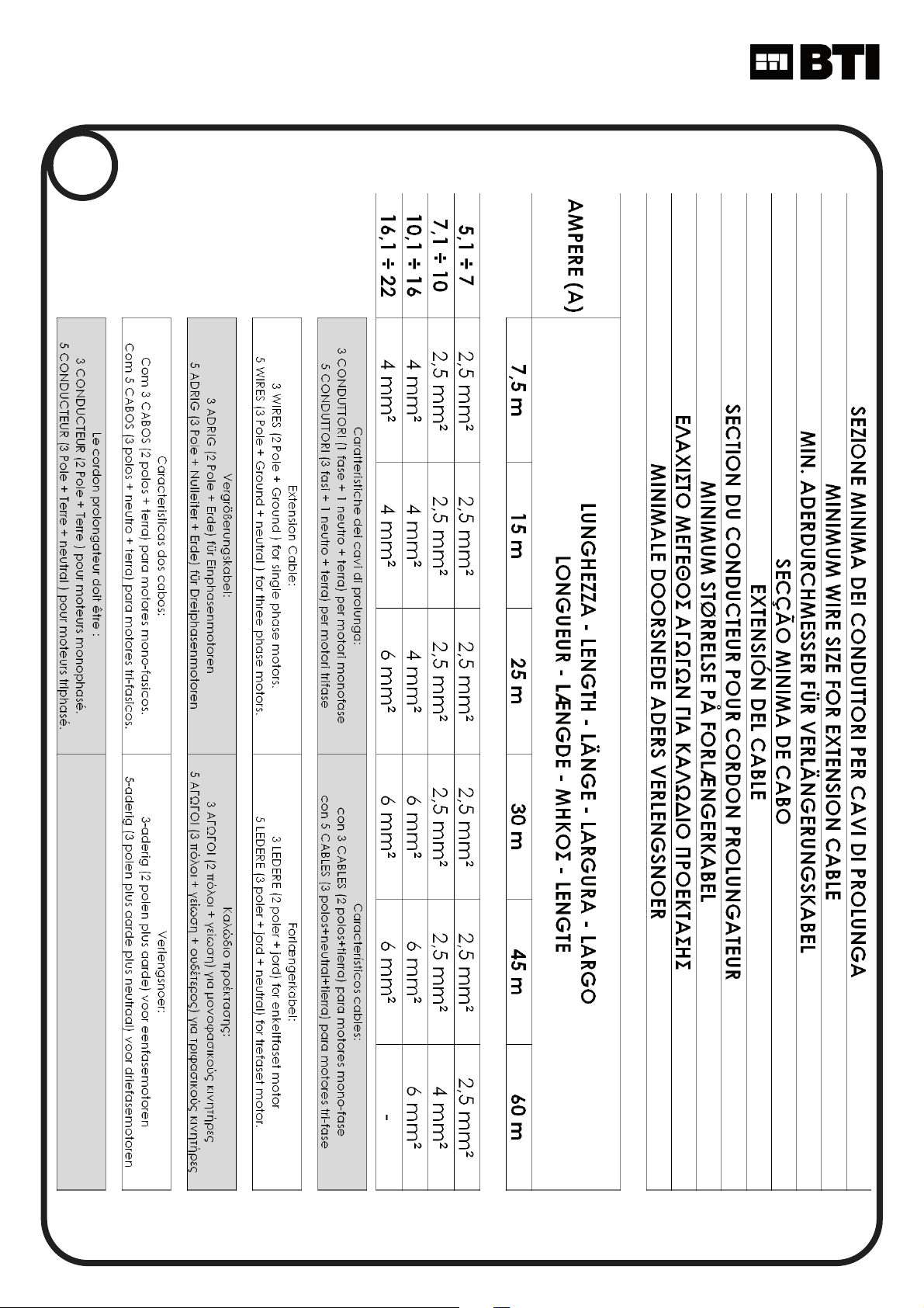
e) Quando si aziona un utensile elettrico
all'esterno, usare un cavo di estensione
(prolunga) adeguato per l'uso in esterni. L'uso di
un cavo adeguato riduce il rischio di scossa
elettrica.
3) Sicurezza personale
a) Non distrarsi mai, controllare quello che si sta
facendo e usare il buon senso quando si
azionano utensili elettrici. Non azionare
l'utensile quando si è stanchi o sotto l'influsso
di droghe, alcol o medicazioni. Un momento di
disattenzione durante l'azionamento di utensili
elettrici può dare luogo a serie lesioni personali.
b) Usare attrezzature di sicurezza. Indossare
sempre protezioni per gli occhi. L'uso
appropriato di attrezzature di sicurezza quali
maschere anti-polvere, calzature di sicurezza
antiscivolo, casco di sicurezza o protezioni per
l'udito riduce la possibilità di subire lesioni
personali.
c) Evitare le accensioni accidentali. Assicurarsi
che l'interruttore sia in posizione di spento
prima di collegare l'utensile alla rete elettrica.
Trasportare utensili elettrici con il dito
sull'interruttore o collegati in rete con l’interruttore in
posizione di accensione può provocare incidenti.
d) Rimuovere qualsiasi chiave di regolazione
prima di accendere l'utensile elettrico. Una
chiave lasciata attaccata a una parte rotante
dell'utensile elettrico può provocare lesioni
personali.
e) Non sbilanciarsi. Mantenere sempre la
posizione e l'equilibrio appropriati. Questo
permette di controllare meglio l'utensile elettrico in
situazioni impreviste.
f) Vestirsi in modo appropriato. Non indossare
vestiti larghi, collane o oggetti pendenti. Tenere
capelli, indumenti e guanti distanti dalle parti in
movimento. Vestiti larghi, collane, oggetti pendenti
o capelli lunghi possono impigliarsi nelle parti in
movimento.
g) Se sono previsti dispositivi da collegare ad
impianti per l'estrazione e la raccolta di polvere,
accertarsi che siano collegati e usati in maniera
appropriata. L'uso di questi dispositivi può ridurre i
rischi correlati alla polvere.
h) Usare l'impugnatura ausiliaria fornita con
l'utensile elettrico. Il mancato uso
dell'impugnatura ausiliaria può causare la perdita di
controllo dell'utensile che può dare luogo a serie
lesioni personali.
4) Uso e manutenzione degli utensili elettrici
a) Non forzare l'utensile elettrico. Usare l'utensile
adatto per l'operazione da eseguire. L'utensile
elettrico appropriato permette di eseguire il lavoro
con maggiore efficienza e sicurezza senza essere
costretti a superare i parametri d'uso di progetto.
b) Non usare l'utensile elettrico se l'interruttore di
accensione o spegnimento non si aziona
correttamente. Qualsiasi utensile elettrico che non
può essere controllato con l’interruttore è
pericoloso e deve essere sottoposto a riparazioni.
c) Scollegare la spina dalla rete di alimentazione
prima di effettuare qualsiasi regolazione,
cambiare accessori o riporre gli utensili
elettrici. Tale misura di sicurezza preventiva riduce
il rischio di avvio accidentale dell’utensile elettrico.
d) Riporre gli utensili elettrici inutilizzati fuori della
portata dei bambini e non permetterne l'uso a
persone inesperte o che non conoscano queste
istruzioni. Gli utensili elettrici sono pericolosi se
utilizzati da persone inesperte.
e) Effettuare la manutenzione necessaria sugli
utensili elettrici. Verificare il possibile errato
allineamento o bloccaggio delle parti in
movimento, la rottura delle parti e qualsiasi
altra condizione che possa influenzare il

!Italiano 2
funzionamento degli utensili elettrici. Se è
danneggiato, far riparare l'utensile elettrico prima di
utilizzarlo. Numerosi incidenti sono provocati
proprio dal cattivo stato di manutenzione degli
utensili elettrici.
f) Mantenere puliti e affilati gli strumenti di taglio.
Strumenti di taglio in buone condizioni di
manutenzione e con bordi di taglio affilati soffrono
di blocchi con minore probabilità e sono più facili da
controllare.
g) Usare l'utensile elettrico, gli accessori e le
punte ecc., in conformità con queste istruzioni
e nel modo previsto per il tipo particolare di
utensile elettrico, tenendo conto delle
condizioni di lavorazione e dell'operazione da
eseguire. L’uso dell’utensile elettrico per
operazioni diverse da quelle previste può dare
luogo a situazioni pericolose.
5) Assistenza
a) Far riparare l'utensile elettrico solo da tecnici
qualificati e utilizzare soltanto ricambi identici.
Questo garantisce la costante sicurezza
dell’utensile elettrico.
Ulteriori disposizioni di sicurezza per carotatrici
Indossare
sempre
occhiali
protettivi
Indossare
guanti
protettivi
Indossare
sempre
protezioni
per l’udito
Indossare
calzature
protettive
Indossare
maschere
antipolvere
I
Is
st
tr
ru
uz
zi
io
on
ni
i
d
da
a
s
se
eg
gu
ui
ir
re
e
p
pr
ri
im
ma
a
d
de
el
ll
la
a
m
me
es
ss
sa
a
i
in
n
f
fu
un
nz
zi
io
on
ne
e
Leggere attentamente i dati riportati sulla
targhetta della carotatrice e della scheda Dati
tecnici fornita con il prodotto.
Per le illustrazioni si faccia riferimento alle pagine iniziali di
questo manuale. Nel testo che segue le figure sono
identificate da numeri mentre i singoli particolari, all'interno
delle figure, sono identificati da lettere.
Il vostro motoriduttore elettrico è idoneo a formare una
carotatrice che rispetti la normativa quando venga utilizzato
con un supporto adatto, fissato adeguatamente.
Alimentazione elettrica
Messa a terra
! il vostro motoriduttore è dotato di collegamento a
terra delle parti metalliche (messa a terra);
! assicurarsi quindi che anche la presa ed eventuali
prolunghe o multiple a cui viene collegato il
motoriduttore siano dotati di conduttore di terra e
che l'impianto elettrico di alimentazione sia
debitamente messo a terra
Attenzione: questo requisito di sicurezza
è di fondamentale importanza. In caso di
dubbio richiedere un controllo accurato
dell'impianto da parte di personale
professionalmente qualificato.
Prolunghe
! nel caso in cui il materiale da forare sia lontano da
una presa di corrente possono essere utilizzati cavi
di prolunga che devono essere di sezione adeguata
e provvisti di conduttore di terra;
! tali cavi di prolunga, costituiti da cavo, spina e
presa, devono essere adatti all'uso esterno e
preferibilmente in gomma e del tipo H07RN-F;
! attenersi scrupolosamente alla tabella in figura 10
di questo manuale per la scelta della sezione dei
conduttori;
! se si utilizza più di un cavo di prolunga per
realizzare la lunghezza totale desiderata, accertarsi
che ciascun cavo di prolunga abbia una sezione dei
conduttori non inferiore a quanto indicato nella
tabella in relazione alla lunghezza totale;
! limitare al minimo possibile la lunghezza delle
prolunghe in quanto ogni prolunga provoca una
caduta di tensione e peggiora il funzionamento del
motoriduttore.
Preparazione della carotatrice
Per preparare la vostra carotatrice alla foratura, operare
come indicato nei punti successivi, accertandosi, prima, che
la spina sia staccata dalla rete di alimentazione elettrica.
! per il fissaggio del supporto al materiale
da forare, attenersi alle indicazioni fornite
dal costruttore del supporto stesso;
! per il montaggio del motoriduttore sul
supporto, attenersi alle indicazioni fornite
dal costruttore del supporto stesso;
Procedere quindi come indicato di seguito:
! se si intende forare con acqua, collegare il tubo di
adduzione dell'acqua alla carotatrice nelle modalità
descritte successivamente nel paragrafo Adduzione
dell’acqua, assicurandosi che il rubinetto sia chiuso,
ossia perpendicolare all’asse del tubo;
! se un cambio di velocità (figura 2A) è disponibile,
selezionare ed impostare la velocità di rotazione
adatta a seconda del diametro della corona
utilizzata facendo riferimento alla targhetta dati
applicata sul motoriduttore, come evidenziato nella
figura 6. La selezione della velocità deve essere
effettuata a motore fermo: non cambiare la velocità
a motore in moto;
! per il montaggio della corona diamantata sul
motoriduttore si faccia riferimento al successivo
paragrafo Montaggio e sostituzione della corona
diamantata;
Elementi di sicurezza
Il vostro motoriduttore, a seconda dei casi, può essere
fornito di uno dei sistemi di sicurezza qui di seguito riportati:
a) Per motoriduttori monofase: PRCD (interruttore
differenziale portatile montato sul cavo di
alimentazione)
! il vostro motoriduttore è dotato di un interruttore
differenziale (PRCD) montato sul cavo,
rappresentato nella figura 7;
! non utilizzare mai il motoriduttore senza il PRCD
montato sul cavo;
! prima di cominciare ad utilizzare il motoriduttore
verificare il corretto funzionamento del dispositivo
PRCD: collegare il motoriduttore all'impianto
elettrico e premere quindi il tasto verde Reset (M).
Questo provoca l’accensione una spia rossa (L)
che segnala le disponibilità di tensione. Azionare
quindi il tasto blu Test (N), che verifica il
funzionamento del dispositivo, che deve
automaticamente scattare in posizione 0 (OFF),
parallelamente a questo la spia rossa deve
spegnersi;
! se durante il lavoro l'interruttore differenziale
dovesse scattare, interrompendo l'alimentazione,
sospendere la perforazione, posizionare
l'interruttore del motoriduttore in posizione OFF e
provvedere a ricercare ed eliminare la causa di

3 Italiano
!
dispersione ricorrendo alle prestazioni di un centro
di assistenza qualificato.
b) Per motoriduttori bimotore a doppia
alimentazione: quadro elettrico portatile di
sicurezza
! il motoriduttore è provvisto di un quadro elettrico di
sicurezza ad una o più prese, dotato di interruttore
differenziale incorporato e una presa speciale cui
collegare il vostro motoriduttore. Questo dispositivo
è rappresentato in figura 8;
! il quadro può essere collegato ad una presa a 5 poli
dotata di neutro (3 fasi + neutro + terra), in questo
modo è possibile far funzionare il motoriduttore alla
massima potenza. Il motoriduttore non deve essere
collegato a prese trifase a 4 poli (senza neutro).
! il quadro può anche essere collegato ad una rete
monofase, utilizzando l'apposito dispositivo (R), in
questo caso la potenza massima utilizzabile dai
motori è quella massima fornita dalla rete;
! non utilizzare mai il motoriduttore senza il quadro
elettrico di sicurezza;
! prima di cominciare il lavoro, controllare il corretto
funzionamento del dispositivo: collegare il
dispositivo all'impianto di alimentazione,
l’accensione della spia Q segnala la presenza di
tensione. Posizionare quindi la leva (S)
dell'interruttore differenziale in posizione "I" (ON).
Quando il dispositivo funziona correttamente,
azionando il tasto di prova (T) (Test), l'interruttore
differenziale deve automaticamente scattare in
posizione "0" (OFF);
! una volta terminata questa verifica, attivare
l’interruttore differenziale S posizionando
l’interruttore in posizione “I”, quindi dare tensione in
uscita al dispositivo premendo il pulsante P. In
modo analogo per togliere tensione in uscita dal
quadro premere il pulsante (O).
! se durante il lavoro l'interruttore differenziale
dovesse scattare, interrompendo l'alimentazione,
sospendere la perforazione, spegnere l'interruttore
di comando sul vostro motoriduttore portandolo in
posizione “O” (figura 5.2) e provvedere a ricercare
ed eliminare la causa di dispersione ricorrendo alle
prestazioni di un centro di assistenza qualificato.
! nella parte posteriore dei motoriduttori bimotori a
doppia alimentazione vi sono due lampade di
controllo (I) rappresentate in figura 5.2.
L'accensione della lampada indica il perfetto
funzionamento del motore corrispondente, al
contrario, lo spegnimento ne indica un
malfunzionamento. Questo può essere dovuto per
esempio alla completa usura delle spazzole del
motore associato. Nel caso di spegnimento di una
lampada interrompere le operazioni di foratura e
rivolgersi ad un riparatore autorizzato BTI.
Interruttore di comando
L’utilizzo dell’interruttore di comando viene spiegato nelle
figure 5.1 e 5.2.
! per i motoriduttori monofase, il funzionamento
dell’interruttore è graficamente illustrato in figura
5.1;
! per i motoriduttori bimotore a doppia alimentazione,
il funzionamento dell’interruttore è graficamente
illustrato in figura 5.2;
Attenzione: per la vostra sicurezza, è
importante familiarizzare con le manovre di
chiusura e apertura dell’interruttore, per
eventuali spegnimenti di emergenza.
Adduzione dell'acqua
Il sistema di adduzione dell’acqua è rappresentato nelle
figure 2 e 3: particolari C e D;
! utilizzare sempre e solo il tubo dell’acqua fornito
con il motoriduttore. Il tubo originale è dotato di un
rubinetto (C) e di una valvola acquastop (D) di
sicurezza;
! l’acqua immessa deve avere una pressione
inferiore a 4 bar;
! utilizzare soltanto acqua pulita;
! impedire che l’acqua entri in contatto con le parti
elettriche del motoriduttore;
! verificare l’integrità dei componenti di adduzione
dell’acqua: il rubinetto (C), la valvola acquastop (D)
e il tubo di immissione.
Controlli e precauzioni per evitare danni
alla struttura o ad impianti esistenti
Prima di utilizzare la vostra carotatrice assicurarsi presso il
capo cantiere o il progettista che le operazioni:
! non alterino le caratteristiche strutturali della
costruzione;
! non danneggino tubazioni dell'acqua o del gas o
conduttori elettrici di ogni sorta.
Controlli e precauzioni per la caduta della
carota
! Prima di forare una parete o una soletta, verificare
che l'eventuale caduta dall’altro lato della carota
non provochi danni. Provvedere comunque a
circoscrivere e segnalare la zona di eventuale
caduta della carota;
! Nel caso in cui l'eventuale caduta della carota
possa creare dei danni o pericoli a cose o persone,
realizzare un adeguato sistema di sostegno capace
di trattenere la carota a fine perforazione.
Scelta del tipo di corona
Il diametro massimo e minimo della corona è riportato sulla
targhetta dati applicata sul vostro motoriduttore. Non
utilizzare corone di diametro diverso da quanto prescritto.
Attenzione: per la vostra sicurezza non utilizzare
corone di tipo diverso da quanto prescritto per la
specifica applicazione.
Il tipo di corona da utilizzare è diverso in funzione del
materiale da perforare e del tipo di perforazione: consultare
il rivenditore per avere informazioni sulla corona più idonea
alla vostra applicazione. La corona non adatta al materiale
da forare o la corona poco tagliente comporta: un forte
sovraccarico del motore, con conseguenti possibili danni
allo stesso, tempi di perforazione eccessivamente lunghi e
una forte usura dei segmenti diamantati.
Montaggio e sostituzione della corona
diamantata
Per il montaggio e la sostituzione della corona diamantata
fare riferimento alla figura 4.
! prima di montare o smontare una corona (L)
interrompere sempre l'alimentazione elettrica,
staccando la spina dalla rete di alimentazione;
! lubrificare la filettatura della corona e dell'albero
portacorona per facilitarne poi lo smontaggio;
! nel caso si abbia una corona con attacco differente
da quello dell'albero portacorona (es. 1/2 G) sono
disponibili, come accessori BTI, appositi raccordi;

!Italiano 4
! se disponibile, frapporre fra l'albero portacorona e
la corona un anello di sbloccaggio rapido (E);
! prima di avviare la perforazione controllare sempre
che la corona sia ben serrata sull'albero
portacorona della macchina.
Supporto
Attenzione: per la vostra sicurezza verificare
sempre che il supporto che state per utilizzare sia
idoneo a supportare la corona di diametro
utilizzato e la potenza del motoriduttore, riportata
sulla targhetta dati sul vostro motoriduttore.
Il motoriduttore deve essere fissato utilizzando un numero
minimo di viti pari a quello indicato nella scheda Dati
Tecnici, allegata al prodotto.
Fissaggio del pezzo in lavorazione / Limiti
dimensionali del pezzo in lavorazione
! si presti particolare attenzione nel caso in cui si
forino blocchi di materiale che non siano parte
integrante di una costruzione. In tal caso si
provveda a fissarli rigidamente;
! evitare assolutamente che durante la perforazione
tali blocchi possano muoversi o essere strappati
dagli ancoraggi.
Limitazioni alle condizioni ambientali
! non esporre il motoriduttore a pioggia, grandine o
neve ed evitare, in ogni caso, che qualsiasi liquido
entri in contatto con le parti elettriche della vostra
carotatrice;
! non utilizzare la carotatrice in atmosfere esplosive,
per esempio in presenza di liquidi, gas o polveri
infiammabili. Il motoriduttore elettrico crea scintille
che possono provocare l'accensione di polveri o
fumi.
Carotaggio sopratesta
Il carotaggio sopratesta (carotaggio soffitti) può essere
effettuato quando la carotatrice è utilizzata nella modalità a
secco. Nella modalità con acqua la foratura sopratesta è
permessa soltanto nel momento in cui vengono utilizzati
appositi dispositivi per evitare che l’acqua entri in contatto
con le parti elettriche. Questi dispositivi sono disponibili
come accessori BTI.
Attenzione: prestare particolare attenzione alla
possibile caduta della carota.
I
Is
st
tr
ru
uz
zi
io
on
ni
i
p
pe
er
r
l
la
a
p
pe
er
rf
fo
or
ra
az
zi
io
on
ne
e
Dopo aver seguito le istruzioni per la preparazione della
carotatrice, per effettuare la perforazione seguire le seguenti
indicazioni:
Attenzione: non toccare con mani o con altre
parti del corpo gli organi in movimento come
corone, dischi o alberi.
! avviare il motore, tenendo la corona staccata dalla
superficie che dovrà essere perforata e,
successivamente, agendo sul sistema di
avanzamento del supporto, avvicinare l'utensile in
rotazione al materiale da forare. Esercitando una
pressione leggera eseguire il primo centimetro di
perforazione: questa operazione è molto importante
perché, se effettuata correttamente, assicura una
perfetta centratura della corona, evitando deviazioni
laterali della stessa durante la continuazione del
foro. In ogni caso riferirsi alle istruzioni fornite dal
produttore del supporto.
! terminata l’operazione di centraggio, se si vuole
forare con acqua aprire il rubinetto (C), disponendo
la leva parallelamente al tubo, in modo da far si che
l’acqua esca dal centro della corona.
! aumentare quindi la spinta sino ad ottenere la
velocità di penetrazione desiderata. Una spinta
insufficiente, provocando la lucidatura del settore
diamantato, ne riduce la capacità di taglio;
viceversa, una spinta eccessiva provoca una rapida
usura del settore diamantato;
! durante la perforazione mantenere fisso l’asse della
corona, evitando possibili spostamenti dell’asse
della stessa. Tali disassamenti comportano, infatti,
una notevole perdita di potenza per l'eccessivo
attrito del mantello della corona sul materiale da
forare. Inconvenienti analoghi si verificano nel caso
in cui il supporto sia male ancorato e dovesse
subire dei piccoli spostamenti;
! qualora non sia possibile proseguire nella
perforazione rinunciare al foro che si sta
effettuando e praticare un secondo foro, coassiale
al primo (sovraforatura), di diametro superiore di
almeno 15 - 20 mm;
! la presenza nell'area di perforazione di materiali
teneri quali legno, sughero, gomma, polistirolo, ecc.
può creare difficoltà nell'avanzamento della corona,
costringendo talvolta a sospendere la foratura ed a
spostare il centro del foro; in tal caso provvedere ad
estrarre la carota relativa alla parte di foro effettuata
e rimuovere le parti di materiale di ostacolo, quindi
procedete nella perforazione;
! nel caso di improvvisa mancanza dell’energia
elettrica, posizionare l’interruttore del motoriduttore
in posizione spento, in modo da evitarne
l’improvvisa e non intenzionale accensione nel
momento in cui l’energia elettrica viene ripristinata;
A perforazione ultimata, si consiglia di:
! arrestare il motore, mantenendo l’erogazione
dell’acqua;
! sollevare la corona diamantata, agendo sul sistema
di avanzamento del supporto fino ad estrarla dal
foro effettuato;
! sospendere l'erogazione dell'acqua;
! prestare attenzione al fatto che la corona
diamantata potrebbe essere calda e causare
ustioni.
Frizione meccanica e arresto improvviso
della corona (stallo)
! spegnere velocemente l'interruttore di accensione
del motoriduttore, se, durante la perforazione, la
corona si dovesse incastrare. Mantenersi sempre
pronti ad effettuare tale operazione di spegnimento;
! il motoriduttore è dotato di una frizione meccanica
che interviene in caso di improvviso arresto della
corona; ciò non esonera, tuttavia, dall'essere
tempestivi nello spegnere il motore agendo
sull'interruttore;
! qualora la corona risultasse bloccata nel foro,
provvedere a liberarla, aiutandosi con una chiave
che si impegni sull'esagono di attacco della corona.
Tale operazione deve essere eseguita a motore
spento;
! qualora ciò non fosse possibile, utilizzare una
chiave a catena che abbracci la corona, avendo
cura di non danneggiare il mantello della stessa.
A
ttenzione: non effettuare tale operazione

5 Italiano
!
di sblocco della corona aiutandosi
accendendo il motore.
Elettronica
Il vostro motoriduttore è dotato dell'elettronica multifunzione
BTI che comprende un sistema di soft-start e una frizione
elettronica.
! il soft-start permette la partenza lenta, riduce il
valore della corrente di spunto all'avviamento,
facilita l’inizio del carotaggio con la messa in
movimento graduale della corona, evitando strappi,
e permette l'impiego del motoriduttore anche
collegato a reti elettriche civili dotate di interruttori
automatici;
! la frizione elettronica toglie potenza al motore nel
caso di eccessivo sovraccarico, evitando possibili
danni alla carotatrice e limitando ulteriormente
strappi sulle braccia dell’operatore. Non appena
viene meno la causa all'origine del sovraccarico la
frizione elettronica ridà automaticamente piena
potenza al motore;
! un intervento frequente della frizione elettronica è
tipicamente causato da velocità di avanzamento
eccessiva, disassamento dell'asse di foratura o
eccessiva profondità di foratura.
Esecuzione di fori di profondità superiore
alla lunghezza della corona
Per eseguire fori di profondità superiore alla lunghezza della
corona seguire i seguenti passi:
! effettuare la perforazione per la lunghezza utile
della corona;
! estrarre la corona dal foro e rimuovere la carota
prodotta;
! posizionare quindi fra corona e macchina la
prolunga necessaria;
! reinserire delicatamente la corona nel foro
effettuato e procedere nella perforazione.
M
Ma
an
nu
ut
te
en
nz
zi
io
on
ne
e
-
-
A
As
ss
si
is
st
te
en
nz
za
a
-
-
G
Ga
ar
ra
an
nz
zi
ia
a
Operazioni periodiche di pulizia,
manutenzione e lubrificazione
! al termine di ogni giornata di lavoro, dopo aver
rimosso la corona, soffiare un getto d'aria all'interno
del motore, con motore in moto, per espellere
eventuali impurità. Effettuate tale operazione
indossando occhiali protettivi;
! prima di eseguire le altre operazioni di
manutenzione, pulizia o lubrificazione assicurarsi
che il motoriduttore sia disconnesso dalla rete
elettrica;
! rimuovere sempre le impurità e i residui del taglio
dal motoriduttore, specialmente dalle parti mobili;
! mantenere pulito ed asciutto il motoriduttore, in
particolare le impugnature;
! non utilizzare solventi o altri prodotti chimici
aggressivi per pulire il motoriduttore;
! dopo l'uso riporre il motoriduttore in un luogo
asciutto, sicuro ed inaccessibile ai bambini;
! mantenere lubrificata la filettatura dell'albero porta
corona;
! il riduttore è lubrificato con olio e/o grasso adatti a
qualsiasi temperatura ambientale. Non sono
necessari controlli di livello o rabbocchi;
! disinserire sempre la spina dalla rete di
alimentazione quando si ispeziona la macchina o si
sostituisce l'utensile di taglio;
! non staccare mai la spina dalla presa di corrente
utilizzando il cavo di alimentazione;
! ispezionare spesso il cavo di alimentazione ed
eventuali prolunghe, accertandosi che non vi siano
danni quali tagli, abrasioni o conduttori in vista. In
tal caso richiedere la sostituzione ad un centro
assistenza BTI;
! non utilizzare il motoriduttore con parti danneggiate
o con difetti di funzionamento, in particolare nel
caso in cui l'interruttore dovesse presentare difetti
nell'accensione o nello spegnimento. In questi casi
provvedere a fare sostituire tali parti presso un
centro di assistenza autorizzato.
Assistenza
! è necessario far controllare il motoriduttore dopo un
periodo di 250 ore di lavoro presso il più vicino
centro di assistenza autorizzato BTI;
! eventuali riparazioni o interventi di assistenza
devono essere effettuati esclusivamente da un
centro di assistenza autorizzato BTI. Rivolgersi al
rivenditore per identificare il centro assistenza
autorizzato più vicino.
! il numero di matricola del vostro motoriduttore è
stampigliato sul prodotto oppure indicato sulla
targhetta dati come nella figura 9;
! richiedere sempre l'uso di parti di ricambio originali
BTI.
Garanzia da parte del costruttore
Questo prodotto è coperto da garanzia di 36 mesi della data
di acquisto contro difetti di materiale ed errori di progetto o
fabbricazione. La garanzia copre il costo della sostituzione
delle parti interessate, il costo delle operazioni di
sostituzione e il materiale di consumo, come olio e
lubrificanti, se integri al momento della riparazione.
La garanzia non comprende la sostituzione di:
! parti di prodotti che hanno subito interventi da parte
di persone non autorizzate;
! parti danneggiate per incuria, uso non adeguato o
sovraccarico;
! parti del prodotto al quale elementi di sicurezza
siano stati rimossi o manomessi;
! materiale di consumo esaurito, sostituito durante la
riparazione.
L'entrata dell'acqua nelle parti elettriche, la mancanza di
pulizia periodica, il danneggiamento delle parti filettate o dei
piani di appoggio degli alberi ecc., sono considerate incurie
e fanno decadere il diritto all'assistenza in garanzia.
La durata delle parti di consumo non è definibile a priori,
essendo in relazione al tempo di utilizzo del prodotto e
all'intensità di lavoro. Esempi di parti di consumo sono:
interruttori, spine e cavi, spazzole, collettore, dischi frizione,
cuscinetti a rulli e a sfera non in bagno d’olio, anelli di
tenuta, sistemi di guida, filtri, ecc.
Se durante la riparazione in garanzia vengono rilevati
deterioramenti di parti di consumo, che possono influenzare
la sicurezza o la funzionalità del prodotto, al cliente è
chiesto di accettare l'onere del pagamento delle parti non
soggette alla garanzia. Il rifiuto di ristabilire le condizioni
della sicurezza iniziale porta al rifiuto di ogni prestazione di
riparazione.

!Italiano 6
La garanzia assicura la sostituzione gratuita delle parti
riconosciute difettose, per fabbricazione o per montaggio, di
prodotti resi ad un centro autorizzato se:
! è fornita una prova della data di acquisto del
prodotto. Sono ritenute prove valide i DDT
(documenti di trasporto) e le fatture
accompagnatorie;
! è stata eseguita correttamente la manutenzione
programmata ogni 250 ore di funzionamento con la
sostituzione delle parti soggette a usura, come ad
esempio le spazzole;
! il prodotto non è stato manomesso da personale
non adeguatamente istruito ed autorizzato da BTI;
! il prodotto è stato sempre usato in conformità a
quanto indicato in questo manuale di istruzioni;
! le indicazione di sicurezza riportate nel manuale di
istruzioni siano state osservate.
BTI non riconoscerà la riparazione in garanzia se:
! il prodotto è stato manomesso da personale non
autorizzato espressamente da BTI;
! i danni sono stati provocati da un utilizzo scorretto o
da incuria. Ammaccature dovute a cadute o colpi
ricevuti saranno considerate effetti di incuria;
! i danni sono stati provocati da sovraccarico
meccanico o elettrico;
! i danni sono stati causati da ingresso dell’acqua o
dei fanghi all'interno del prodotto.
Nel periodo del garanzia, in alcuni casi, come nel caso in cui
i tecnici autorizzati BTI ritengano la riparazione troppo
onerosa, è prevista la sostituzione gratuita del prodotto. La
sostituzione in garanzia del prodotto viene garantita, inoltre,
dopo due tentativi infruttuosi di riparazione e dopo un
colloquio con i responsabili di un centro assistenza BTI. In
caso di sostituzione del prodotto viene normalmente
addebitato l’ammontare corrispondente alla normale usura
delle parti del prodotto sostituito.
Elenco delle parti sostituibili dall'utente
Nessuna parte dell’utensile elettrico BTI è sostituibile
dall’utente. La sostituzione deve essere effettuata da un
riparatore autorizzato BTI.
Centri di assistenza BTI - Elenco indirizzi
Per l'elenco dei centri di assistenza rivolgersi al rivenditore.
E
El
le
en
nc
co
o
d
de
ei
i
c
co
on
nt
te
en
nu
ut
ti
i
d
de
el
ll
la
a
c
co
on
nf
fe
ez
zi
io
on
ne
e
Fare riferimento alla Distinta Ricambi, specifica per il
modello, contenuta nella confezione insieme a questo
manuale.
Prodotti giunti a fine vita.
Il simbolo a sinistra, che compare sull'etichetta del vostro prodotto BTI o sulla sua confezione, indica che il prodotto non può essere
smaltito come rifiuto domestico al termine della sua vita. In base alla direttiva europea 2002/96/EC, esso deve essere consegnato
ad un punto di raccolta adatto per il riciclo di apparecchi elettrici o elettronici.
È essenziale che questo prodotto venga riciclato o smaltito correttamente. In questa maniera si aiuta a prevenire potenziali
conseguenze negative per l’ambiente e per la salute delle persone. Per informazioni dettagliate su cosa fare quando il prodotto non
è più funzionante e non è più riparabile, vi preghiamo di contattare il rivenditore da cui avete acquistato il prodotto.
Questo prodotto è stato immesso nuovo sul mercato dopo il 13 agosto 2005.
Questo manuale è soggetto a modifiche senza preavviso.
ATTENZIONE:
IL COSTRUTTORE DECLINA OGNI RESPONSABILITA'
IN CASO DI DANNI A PERSONE, ANIMALI O COSE
PROVOCATI DALLA MANCATA OSSERVANZA
DELLE NORME DI SICUREZZA E D'USO SOPRA ELENCATE

7 English
!
Your BTI core drill motor (figure 1, Z) is an electric tool that must be used mounted to a
proper drill stand (X) which must be fastened by an anchoring system (Y). These three
parts together make a diamond core drill (X+Y+Z), suitable to drill into stone-like materials
(reinforced or not reinforced concrete, bricks, stone…) using a core bit. Your core drill
motor conforms with its related regulations. The diamond core drill conforms with the
regulations if the stand and the anchoring system conform with their related regulations.
G
Ge
en
ne
er
ra
al
l
s
sa
af
fe
et
ty
y
r
ru
ul
le
es
s
WARNING! Read all instructions. Failure to follow all
instructions listed below may result in electric shock, fire
and/or serious injury. The term "power tool" in all of the
warnings listed below refers to your mains operated (corded)
power tool or battery operated (cordless) powertool.
SAVE THESE INSTRUCTIONS
1) Work area
b) Keep working area clean and well lit. Cluttered
and dark areas invite accidents.
c) Do not operate power tools in explosive
atmospheres, such as in the presence of
flammable liquids, gases or dust. Power tools
create sparks which may ignite the dust or fumes.
d) Keep children and bystanders away while
operating a power tool. Distractions can cause
you to lose control.
2) Electrical safety
a) Power tool plugs must match the outlet. Never
modify the plug in any way. Do not use any
adapter plugs with earthed (grounded) power
tools. Unmodified plugs and matching outlets will
reduce risk of electric shock.
b) Avoid body contact with earthed or grounded
surfaces such as pipes, radiators, ranges and
refrigerators. There is an increased risk of electric
shock if your body is earthed or grounded.
c) Do not expose power tools to rain or wet
conditions. Water entering a power tool will
increase the risk of electric shock.
d) Do not abuse the cord. Never use the cord for
carrying, pulling or unplugging the power tool.
Keep cord away from heat, oil, sharp edges or
moving parts. Damaged or entangled cords
increase the risk of electric shock.
e) When operating a power tool outdoors, use an
extension cord suitable for outdoor use. Use of
a cord suitable for outdoor use reduces the risk of
electric shock.
3) Personal safety
a) Stay alert, watch what you are doing and use
common sense when operating a power tool.
Do not use a power tool while you are tired or
under the influence of drugs, alcohol or
medication. A moment of inattention while
operating power tools may result in serious
personal injury.
b) Use safety equipments: always wear eye
protection. Safety equipment such as dust mask,
non-skid safety shoes, hard hat, or hearing
protection used for appropriate conditions will
reduce personal injuries.
c) Avoid accidental starting. Ensure the switch is
in the off position before plugging in. Carrying
power tools with your finger on the switch or
plugging in power tools that have the switch on
invites accidents.
d) Remove any adjusting key or wrench before
turning the power tool on. A wrench or a key left
attached to a rotating part of the power tool may
result in personal injury.
e) Do not overreach. Keep proper footing and
balance at all times. This enables better control of
the power tool in unexpected situations.
f) Dress properly. Do not wear loose clothing or
jewellery. Keep your hair, clothing and gloves
away from moving parts. Loose clothes, jewellery
and long hair can be caught in moving parts.
g) If devices are provided for the connection of
dust extraction and collection facilities, ensure
these are connected and properly used. Use of
these devices can reduce dust related hazards.
h) Use auxiliary handles supplied with the tool.
Loss of control can cause personal injury.
4) Power tool use and care
a) Do not force the power tool. Use the correct
power tool for your application. The correct
power tool will do the job better and safer at the
rate for which it was designed.
b) Do not use the power tool if the switch does not
turn it on and off. Any power tool that cannot be
controlled with the switch is dangerous and must
be repaired.
c) Disconnect the plug from the power source
before making any adjustments, changing
accessories, or storing power tools. Such
preventive safety measures reduce the risk of
starting the power tool accidentally.
d) Store idle power tools out of the reach of
children and do not allow persons unfamiliar
with the power tool or these instructions to
operate the power tool. Power tools are
dangerous in the hands of untrained users.
e) Maintain power tools. Check for misalignment
or binding of moving parts, breakage of parts
and any other condition that may affect the
power tools operation. lf damaged, have the
power tool repaired before use. Many accidents are
caused by poorly maintained power tools.
f) Keep cutting tools sharp and clean. Properly
maintained cutting tools with sharp cutting edges
are less likely to binf and are easier to control.
g) Use the power tool, accessories and tool bits
etc., in accordance with these instructions and
in the manner intended for the particular type of
power tool, taking into account the working
conditions and the work to be performed. Use of
the power tool for operations different from
intended could result in a hazardous situation.
5) Service
a) Have your power tool serviced by a qualified
repair person using only identical replacement
parts. This will ensure that the safety of the power
tool is maintained.

!English 8
Additional safety rules for diamond drills
Always
wear safety
goggles
Always
wear
safety
gloves
Always wear
ear
protection
Always
wear safety
shoes
Always
wear dust
mask
I
In
ns
st
tr
ru
uc
ct
ti
io
on
ns
s
b
be
ef
fo
or
re
e
u
us
se
e
Read carefully the data reported on the data plate
of your core drill and on the Technical Data sheet
that you will find in the package together with
your product.
In the following text, figures are identified by numbers,
details inside the figures by letters. Figures are depicted on
the first pages of this user manual.
Your core drill motor is suitable to be a part of a diamond
core drill that conforms with the related regulations if the drill
motor is mounted to a proper drill stand fastened by a
proper anchoring system.
Power supply
Earth (Ground)
! the metallic parts of you core drill motor are
connected to the earth.
! make sure that the socket and possible extension
cords and multiple sockets have the earth
connection and that your electrical system is
properly connected to the earth.
Warning: for your safety, it is important
that the whole system (electrical system,
extension cords, sockets etc.) is connected
to the earth. If you are not sure, ask a
qualified electrician for a check.
Extension cords
! when you have to operate with your core drill motor
far from an electrical socket, you can use an
extension cord. If you use it make sure that the
section of the cord is suitable and that the cord is
provided with ground conductor;
! the extension cord (made up of cable, plug and
socket) must be suitable for outdoor use. It is better
if the cord is made of rubber and it is H07RN-F;
! follow the chart shown in figure 10 on this manual
for the choice of the right section of the conductors;
! if you use more than one extension cord make sure
that every cable in every extension cord has a
section not lower than the value shown on the chart
in figure 10, considering the total length of the
extension cords;
! remember that the more an extension cord is long
the more the voltage drop is high and the worse is
the operation of your core drill. Don’t use extension
cords if you have to operate too far from the
electrical socket.
Preliminary operations
In order to prepare your core drill to operate, follow these
steps. Before proceeding with the preparation make sure
that the plug is disconnected from the electricity network.
! follow the instructions given by the
stand manufacturer for fastening the
stand to the material to be drilled;
! follow the instructions given by the
stand manufacturer for mounting your
core drill motor to the stand;
Follow these instructions:
! if you want to operate in wet mode, connect the
hosepipe to the core drill motor as explained in the
Water insertion paragraph. Make sure that the
water valve is shut;
! if your core drill is equipped with a gear change
(figure 2 A), see the data plate on your core drill
motor as shown in figure 6. Identify the right
rotating speed according to the diameter of the core
bit you are using. Select the required gear change
position just when the motor is at standstill;
! refer to the following paragraph Diamond core bit
mounting and replacement in order to mount the
core bit to your core drill.
Safety systems
Your core drill motor is equipped with one of the safety
device listed here:
For single phase core drill motors: PRCD (portable
residual current device, assembled on the cord, also
known as GFI)
! your core drill motor is equipped with a safety
portable residual current device (PRCD) assembled
on the cord. This device is shown in figure 7;
! never use core drill without PRCD;
! before starting to work make sure the PRCD works
properly. In order to do so, plug the core drill motor
in and press the green button Reset (M): a red led
will light up (L) showing that electricity is available
to the core drill. Than press the blue button Test (N)
that tests if the device works properly. When you
press it the circuit breaker inside the PRCD should
cut the power off leading the switch automatically to
go to the off position and the red led to go off;
! if, when working, the PRCD cuts the power: stop
working, set the switch on OFF position and bring
your core drill to an authorized service centre in
order to remove the causes of the electrical
dissipation.
For twin motors core drill motors: portable electric
safety device box
! the core drill motor is equipped with a portable
electric safety device box which includes: one or
more sockets, a residual current circuit breaker and
a special socket into which you can plug your core
drill motor. This device is shown in figure 8;
! the box can be plugged into a 5-pin socket with
neutral pin (3 phases + neutral + earth). In this case
you provide the motor with the all power it needs.
Do not plug your core drill motor into a 4 pin socket
(without neutral);
! the box can also be connected to a single phase
network using the device R. In this way the
maximum power the motor can have is the
maximum provided by the electric network.
! never use your core drill motor without the safety
device box;
! before starting to work make sure the box works
properly: connect the box to the electric network,
the led Q should light up, showing electricity inside
the device. Than move the residual current device
switch lever (S) to the on position ("I"). In order to
test the device press the test button (T): the
residual current device (S) should automatically go
to the off position ("0");

9 English
!
! once you checked that the device works properly,
switch the S lever to ON, and press the button (P)
what gives power to the sockets. On the contrary,
the button O cuts power to the sockets;
! if, when working, the residual current device goes
off, cutting power to the machine: stop drilling, turn
the ON/OFF switch off (figure 5.2) and eliminate the
cause of dispersion asking to an authorized service
centre.
! on the rear of the twin-motor core drill motor are
located two lights shown in figure 5.2 with I. When
both lights are on the two electric motors are
working properly. If one light is off, means that the
corresponding motor has a problem, for example
the motor brushes are worn. When a light goes off
stop drilling and bring ask an authorized service
centre to fix the problem.
ON/OFF switch
Refer to figure 5.1 and 5.2 in order to understand how to use
the on/off switch:
! single phase core drill motors use the switch shown
in figure 5.1;
! twin-motor core drill motors use the switch shown in
figure 5.2;
Warning: for your safety, you must get
familiar with the switch in order to
understand how you can switch the machine
off in case of emergency.
Connection to a water supply
Wet drilling needs insertion of water into the core drill motor.
Refer to figure 2.
! use only the water pipe provided with your core drill
motor. The water pipe includes also a valve (C) and
a quick hose connector (D);
! the maximum pressure of incoming water is 4 bar;
! use just clean water;
! prevent water from entering the electric motor or
other electrical components;
! check at regular intervals that none of the water
system components are damaged. Check in
particular the valve (C), the quick hose connector
(D) and the pipe.
Checks and precautions to avoid
structural damage and damage to the
plant
Before starting any drilling activity, talk with the construction
manager or the planner in order to make sure that the
drilling doesn’t:
! make any damage to the structure of the building
and doesn’t change the structural characteristics of
the construction;
! damage any water or gas pipeline or any electric
mains.
Checks and precautions to avoid damage
caused by the fall of the core
! before drilling, make sure that the possible falling
out of core from the other side of the hole doesn't
make any damage. In any case, bound the area
where the core can fall and signal the danger;
! if the possible fall of the core can make damage,
make a system that holds the core when drilling is
completed.
Core bit choice
The maximum and minimum core bit diameter is reported on
the data plate on your core drill motor. Do not use core bit
with different diameter from the one prescribed.
Warning: for your safety do not use different core
bits from the ones prescribed for your specific
application
The core bit is different depending on the material to be
drilled: consult your dealer about the correct core bit for your
application. The not suited core bit or a core bit not sharp
can overload the motor leading to: damage to the motor,
long drilling time and excessive diamond segments wearing.
Diamond core bit mounting and
replacement
Follow these directions, refer to figure 4:
! before mounting or removing the core bit (F) always
unplug the core drill motor;
! lubricate the core bit and the core bit spindle thread
in order to make easier, after use, to remove the
core bit;
! if you your core bit connection doesn’t match the
core bit spindle (ex. 1/2 G), use a proper adapter
available among BTI accessory;
! if available interpose a quick release device (E)
between the core bit spindle and the core bit (as
shown in figure 4);
! before starting to drill make sure that the core bit is
firmly screwed on the core bit spindle.
Stand
! Warning: for your safety, make sure that the drill
stand you are using is compatible with the
diameter of the core bit and that it is compatible
with the power of your core drill motor, shown on
the data plate.
The minimum number of bolts you must use to fasten your
drill motor is written on the Technical Data sheet.
Fastening the work piece and size of the
work piece
! if the work object is a block and not part of a
structure, fasten it in order to prevent its movement;
! prevent the work piece from shifting, moving or
falling when you are cutting.
Environmental conditions
! don’t expose the machine to rain, ice or snow;
! prevent water or any other liquid from coming into
contact with the electric parts of your machine;
! do not use the core drill in explosive atmospheres,
for instance in presence of inflammable liquids, gas
or dust. The electric core drill motor produces
sparks which can ignite dust or smoke.
Overhead drilling (ceiling drilling)
You can perform overhead drilling (upward) when the core
drill is used in the dry mode. Overhead drilling is allowed in
the wet mode ONLY if you use proper water collecting
devices in order to avoid water coming into contact with any
electrical parts. These devices are available as BTI
accessories.
Warning: the possible drop of the core can be
dangerous. Watch out!

!English 10
O
Op
pe
er
ra
at
ti
in
ng
g
i
in
ns
st
tr
ru
uc
ct
ti
io
on
ns
s
After having followed the instructions given in the previous
paragraph Preliminary operations, follow these operating
instructions:
Warning: do not touch any moving parts of
your diamond drill when operating.
! switch on the core drill motor, keeping the core bit
not in contact with the material to be drilled. After
this operation, using the moving system of the
stand, move the carriage with the core drill motor
and the rotating core bit closer to the material and,
pressing lightly, drill about 1 cm into the material.
This operation is very important because, if
correctly carried out, leads to a perfect centring and
makes drilling easier. In any case, refer to the
directions provided by the manufacturer of the drill
stand;
! if you want to operate in the wet mode, open the
valve (the valve is open when the handle is parallel
to the water stream). The water should come out
from the centre of the core bit.
! after the centring operation, increase the forward
speed. On one hand, a too low forward speed leads
to polishing of diamond sectors, decreasing their
drilling capacity. On the other hand, a too high
forward speed, leads to a quick segments wear.
! when drilling, make sure that the rotation axis of the
core bit doesn’t move and avoid any possible
movement of it. When the core bit rotation axis
moves, the friction between the wall of the hole and
the core bit leads to a considerable power loss.
This happens for example when the stand is not
firmly fastened to the material to be drilled.
! if you can not continue drilling, you can make a new
hole around the old one (over-drilling), keeping the
same rotation axis. The diameter of the new hole
must be at least 15-20 mm bigger than the diameter
of the old one;
! drilling materials containing wood, cork, rubber,
foam polystyrene can lead to problems moving
forward the core bit. If you have this kind of
problems, pull the core out of the hole and remove
all materials listed before that don’t allow the core
bit to go on and then continue with drilling
operations;
! in case the electric power goes off, set the switch to
the OFF position, in order to prevent the machine
from accidentally self starting;
Once the hole is completed, you should:
! switch the motor off, keeping the water flowing;
! using the moving system of the stand, pull the core
bit out;
! stop the flow of water;
! do not touch the core bit after performing a drill.
The core bit can be very hot and cause severe
burns;
Mechanical clutch and core bit jamming
! be ready to turn the switch of your core drill motor
off, in case of a core bit jamming;
! your BTI core drill motor is equipped with a safety
mechanical clutch that comes into operation in case
of sudden stop of the core bit rotation. Despite your
drill is equipped with this device, you must always
be watchful and be ready to switch off the motor.
! in case of jamming, after having switched the motor
off, try to unclamp the core bit using an hexagonal
spanner hocking on the core bit connection;
! alternatively you can use a chain spanner, paying
attention not to damage the core bit.
Warning: do not try to unclamp the core
bit with the motor is on, or helping yourself
with the motor.
Electronic devices
Your core drill motor is equipped with a BTI multifunction
electronic device that includes a soft-start and an electronic
clutch;
! the soft-start allows the motor soft-start, reduces
current peak that occurs when you switch the motor
on, helps you when you begin drilling, allowing
gradual core bit rotation and avoiding jerks at your
arm, and allows you to use your core drill
connected to the household electric outlet equipped
with automatic switch;
! the electronic clutch makes sure that the current
absorbed by your core drill, proportional to the
motor load, is below the safety upper limit and, in
case the current absorbed exceeds the limit, cuts
off power to the motor, preventing damage. When
the overload is over, the device gives back power to
the motor that begins working again;
! if the electronic clutch operates frequently means
that the core drill is not used properly. Possible
causes can be a not suitable forward speed, an
excessive friction between the core bit and hole
wall or an excessive drilling depth.
Drilling deeper than the core bit length
If you want to make an hole deeper than the core bit length
proceed as follows:
! drill till the end of the core bit;
! pull the core bit out of the hole and remove the
core;
! place a proper core bit extension between the core
bit and the core drill thread;
! insert the core bit in the hole and proceed drilling.
M
Ma
ai
in
nt
te
en
na
an
nc
ce
e
-
-
S
Se
er
rv
vi
ic
ce
e
-
-
W
Wa
ar
rr
ra
an
nt
ty
y
Periodic maintenance
! at the end of the work, after having removed the
core bit, blow compressed air inside the rotating
motor in order to remove dust and powder. Do this
operation wearing protective goggles;
! before starting any other cleaning, maintenance or
lubrication operation make sure that the core drill
motor is unplugged;
! keep lubricate the core-bit shaft thread;
! keep your core drill clean and dry, in particular its
handles;
! never use solvents or other harsh chemicals for
cleaning your core drill motor;
! after use put your core drill in a dry, safe and
inaccessible to children place;
! gears are lubricated by lubricating oil and grease
which are suited for any external temperature. You
don’t have to check the oil level or to fill it up.
! always unplug the core drill motor during check or
replacement;
! never unplug the core drill motor by pulling the
cord;

11 English
!
! inspect often the feeding cable and extension
cords, making sure that they don’t have any
damage like cuts, abrasions or live conductors. If
you find a damage, ask a BTI authorized service
centre for replacement;
! do not use the core drill motor with damaged
components or with malfunctions, in particular when
the switch doesn’t work properly. In these cases,
ask to a BTI authorized service centre for
replacement.
Service
! after 250 hours of work, bring your core drill motor
to a BTI authorized service centre for periodical
check;
! any repairing must be carried out by BTI authorized
service personnel only. Ask your dealer for the list
of the BTI authorized service centres;
! your core drill motor’s serial number is stamped on
the machine or printed on the data plate as shown
in figure 9;
Use original BTI spare parts only.
Warranty
Your product is under BTI warranty for 36 months, starting
from the date of purchase. This warranty is against faulty
workmanship, flaws material and design problems. The
warranty covers free components replacement, manpower
needed for replacement and wearing materials such as oil
and lubricants if intact before the repairing operation. The
warranty doesn't cover the replacement of:
! components of the product replaced or modified by
people not authorized by BTI;
! components damaged by carelessness, not
suitable use or overloaded;
! components of products from which safety devices
have been removed;
! worn wearing parts replaced during repair.
This warranty does not apply to products that have been
damaged by carelessness like water entering the core drill,
lack of periodic cleaning and maintenance, damage of the
threaded components or the spindle etc.
The life of wearing parts is variable depending on the
working time and the kind of work they are used for.
Examples of wearing parts are: cables, switches and plugs,
brushes, commutators, clutch plates, ball and roller bearing
not in oil, sealing rings, transmission spindles, filters, etc.
If during repairing under warranty, a wearing part is worn
and this can affect the safety and the operation of your
product, the customer is asked to pay for the replacement of
these components not under warranty. If the customer
refuses this, no repairing operation will be carried out.
The warranty covers free replacement of components which
are defective due to wrong manufacturing or assembly, if the
product is brought to an authorized service centre and if:
! the product is together with a purchasing document
stating when the product has been purchased.
Valid purchasing documents are invoices or
delivery certificates;
! maintenance operations have been carried out
every 250 working hours, replacing the worn
wearing parts;
! no unauthorized people have operated on the
product;
! the product has not been misused and it has been
used accordingly with the directions given in this
user manual;
! all safety directions have been followed.
Your BTI product is not under warranty if:
! the product has been serviced by people not
authorized by BTI.
! damage is due to incorrect use and/or
carelessness. Dents due to drops or strokes will be
considered evidence of carelessness;
! damage has been caused by mechanical or
electrical overload;
! damage has been caused by water, mud or any
other liquid entering the product.
When your product is under warranty, in some cases, like if
the BTI authorized service personnel think the repairing is
too expensive to be carried out, the free substitution of the
product is possible. In addition, the substitution under
warranty is provided after two fruitless reparation attempts
and after the authorization of a BTI service manager. In
case of substitution, the customer is, usually, requested to
pay for the worn wearing parts of the replaced product.
User-replaceable components
No components of your BTI product can be replaced by the
user. Replacement must be carried out by BTI authorized
personnel only.
BTI service centres - Address list
Ask your dealer for a BTI service centres address list.
P
Pa
ac
ck
ka
ag
ge
e
c
co
on
nt
te
en
nt
ts
s
For the list of contents refer to the Spare Parts List, specific
for your model, located in the package together with this
manual.
Products to the end of their life.
The symbol on the left, that you can find on the product or on its packaging indicates that this product may not be treated as
household waste. At the end of its life the products must be handed over to the applicable collection point for the recycling of
electrical and electronic equipment.
Be sure that this product is disposed correctly. You will help prevent potential negative consequences for the environment and
human health. For more detailed information about what to do when your product doesn't work and is not fixable, contact the dealer
where you did purchase the product.
Your product has been introduced new on the market after August 13th 2005.
This manual is subject to modifications without notice.
WARNING:
THE MANUFACTURER DECLINES ALL RESPONSABILITY
IN CASE OF NO RESPECT OF THE ABOVE WRITTEN
"SAFETY AND OPERATING INSTRUCTIONS".

!Deutsch 12
Ihr BTI-Kernbohrmotor (Abb. 1, Z) ist ein Elektrowerkzeug, das an einem geeigneten
Bohrstativ (X) montiert benutzt werden muss, welches an einem Verankerungssystem (Y)
befestigt werden muss. Ein Kernbohrsystem besteht aus diesen drei Teilen (X+Y+Z), mit
dem steinähnliche Stoffe (bewehrter oder unbewehrter Beton, Ziegel, Stein, ...) mittels
einer Kernbohrkrone gebohrt werden können. Ihr Kernbohrmotor entspricht den
einschlägigen Bestimmungen. Die Diamantkernbohrmaschine entspricht den
Bestimmungen, wenn das Stativ und das Verankerungssystem ihren einschlägigen
Bestimmungen entsprechen.
A
Al
ll
lg
ge
em
me
ei
in
ne
e
S
Si
ic
ch
he
er
rh
he
ei
it
ts
sb
be
es
st
ti
im
mm
mu
un
ng
ge
en
n
WARNUNG! Lesen Sie alle Anweisungen durch. Wenn Sie
die unten aufgeführten Anweisungen nicht befolgen, kann es
zum Stromschlag, Brand und/oder zu schweren
Verletzungen kommen. Der Ausdruck "Elektrowerkzeug" in
allen unten aufgeführten Warnungen bezieht sich auf Ihr
netzgespeistes (verkabeltes) oder akkugespeistes
(unverkabeltes) Elektrowerkzeug.
Bewahren Sie alle Warnhinweise und sonstigen
Anweisungen zur künftigen Bezugnahme auf.
1) Arbeitsbereich-Sicherheit
a) Halten Sie Ihren Arbeitsbereich sauber und gut
ausgeleuchtet. Unordnung und dunkle
Arbeitsbereiche fordern Unfälle geradezu heraus.
b) Arbeiten Sie mit Geräten nicht in
explosionsgefährdeter Umgebung, in der sich
brennbare Flüssigkeiten, Gase oder Stäube
befinden. Geräte erzeugen Funken, die den Staub
oder die Dämpfe entzünden können.
c) Halten Sie Kinder und andere Personen während
der Benutzung des Gerätes fern. Bei Ablenkung
können Sie die Kontrolle verlieren.
2) Elektrische Sicherheit
a) Der Anschlußstecker des Gerätes muß in die
Steckdose passen. Der Stecker darf in keiner
Weise verändert werden. Verwenden Sie keine
Adapterstecker gemeinsam mit schutzgeerdeten
Geräten. Unveränderte Stecker und passende
Steckdosen verringern das Risiko eines elektrischen
Schlages.
b) Vermeiden Sie Körperkontakt mit geerdeten
Oberflächen von Rohren, Heizungen, Herden
und Kühlschränken. Es besteht ein erhöhtes
Risiko eines elektrischen Schlags, wenn Ihr Körper
geerdet ist.
c) Halten Sie Geräte von Regen und Nässe fern.
Das Eindringen von Wasser in ein Gerät erhöht das
Risiko eines elektrischen Schlages.
d) Mißbrauchen Sie nicht das Kabel. Verwenden
Sie das Kabel niemals zum Tragen, Ziehen oder
Trennen des Gerätes vom Netz. Halten Sie das
Kabel fern von Hitze, Öl, scharfen Kanten oder
sich bewegenden Teilen. Beschädigte oder
verwickelte Kabel erhöhen das Risiko eines
elektrischen Schlages.
e) Wenn Sie mit einem Gerät im Freien arbeiten,
verwenden Sie nur Verlängerungskabel, die
auch für den Außenbereich zugelassen sind. Die
Verwendung eines für den Außenbereich
geeigneten Verlängerungskabels verringert das
Risiko eines elektrischen Schlages.
3) Sicherheit von Personen
a) Seien Sie aufmerksam, achten Sie darauf, was
Sie tun, und gehen Sie vernünftig mit einem
Gerät um. Benutzen Sie das Gerät nicht, wenn
Sie müde sind oder unter dem Einfluß von
Drogen, Alkohol oder Medikamenten stehen. Ein
Moment der Unachtsamkeit beim Gebrauch von
Geräten kann zu ernsthaften Verletzungen führen.
b) Verwenden Sie Schutzausrüstung. Tragen Sie
stets einen Augenschutz. Schutzausrüstung wie
Staubmaske, rutschfeste Sicherheitsschuhe,
Schutzhelm oder Gehörschutz, je nach Art und
Einsatz des Gerätes, verringert das Risiko von
Verletzungen.
c) Vermeiden Sie eine unbeabsichtigte
Inbetriebnahme. Stellen Sie sicher, daß sich der
Schalter in der Aus-Stellung befindet, bevor das
Gerät mit dem Netz verbunden wird. Durch das
Tragen des Gerätes mit dem Finger am Schalter
oder durch das Verbinden eingeschalteter Geräte
werden Unfälle provoziert.
d) Entfernen Sie Einstell- oder
Schraubenschlüssel, bevor Sie das Gerät
einschalten. Ein Schlüssel, der sich in einem sich
drehenden Teil befindet, kann zu Verletzungen
führen.
e) Nicht zu weit nach vorne strecken! Achten Sie
auf einen sicheren Stand, um in jeder
Arbeitsposition das Gleichgewicht zu halten.
Dadurch können Sie das Gerät in unerwarteten
Situationen besser unter Kontrolle halten.
f) Tragen Sie geeignete Kleidung. Tragen Sie keine
weite Kleidung oder Schmuck. Halten Sie Haare,
Kleidung und Handschuhe fern von sich
bewegenden Teilen. Lockere Kleidung, Schmuck
oder lange Haare können von sich bewegenden
Teilen erfaßt werden.
g) Falls Staubabsaug- und –fangvorrichtungen
vorhanden sind, vergewissern Sie sich, daß
diese angeschlossen sind und richtig verwendet
werden. Die Verwendung von
Staubfangeinrichtungen kann die mit Staub
verbundenen Gefahren verringern.
4) Gebrauch und Pflege von Geräten
a) Überlasten Sie das Gerät nicht. Verwenden Sie
für Ihre Arbeit das dafür bestimmte Gerät. Mit
dem passenden Gerät arbeiten Sie besser und
sicherer im angegebenen Leistungsbereich.
b) Benutzen Sie kein Gerät, dessen Schalter defekt
ist. Ein Gerät, das sich nicht mehr ein- oder
ausschalten läßt, ist gefährlich und muß repariert
werden.
c) Trennen Sie den Stecker von der Stromquelle
und/oder das Akkupaket vom Elektrowerkzeug,
bevor Einstellungen vorgenommen, Zubehör
gewechselt oder Elektrowerkzeuge verstaut
werden. Diese Vorsichtsmaßnahmen verhindern
den unbeabsichtigten Start des Gerätes.
This manual suits for next models
1
Table of contents
Languages:
Other BTI Drill manuals

BTI
BTI A18 SBS BL User manual

BTI
BTI BM 701 E User manual

BTI
BTI SB 1100 E User manual

BTI
BTI PROFILINE BM 550 E User manual

BTI
BTI A18 BS User manual

BTI
BTI A-BS2 10,8 V LI S User manual

BTI
BTI A-BS 12 V User manual

BTI
BTI A-BS BL 10,8 V User manual

BTI
BTI BTI-BM 10 E User manual

BTI
BTI Profiline A-BS 12V User manual
Popular Drill manuals by other brands

Osaki Power Tools
Osaki Power Tools IDH013 Operator's manual

Black & Decker
Black & Decker GC9600 instruction manual

Asset construction hire
Asset construction hire Hilti TE60-ATC Safety sheet

Urrea
Urrea Rotomartillo RM812D user manual

Makita
Makita HP2050 instruction manual

Ingersoll-Rand
Ingersoll-Rand W1110 user manual