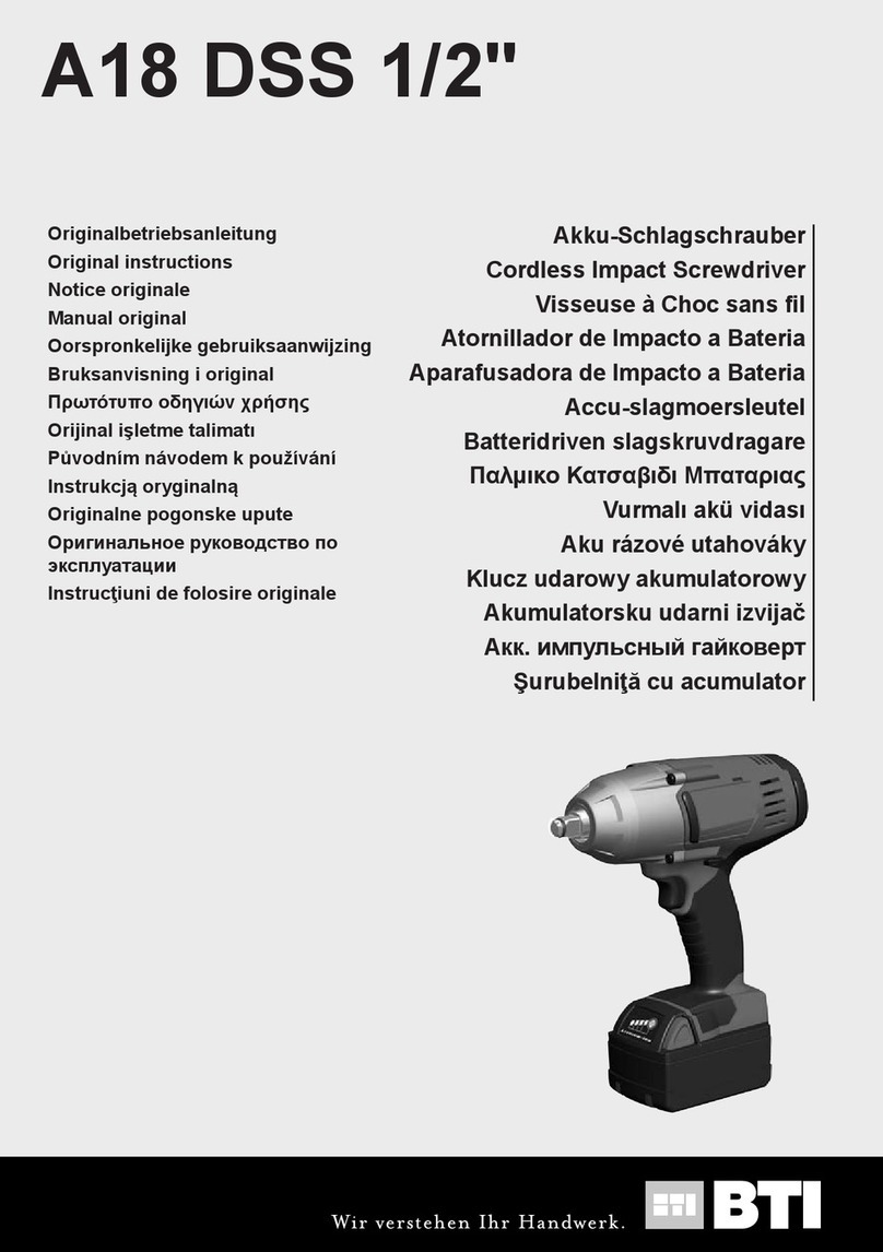
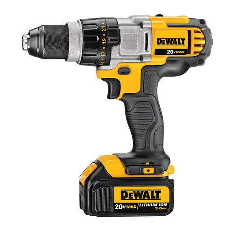
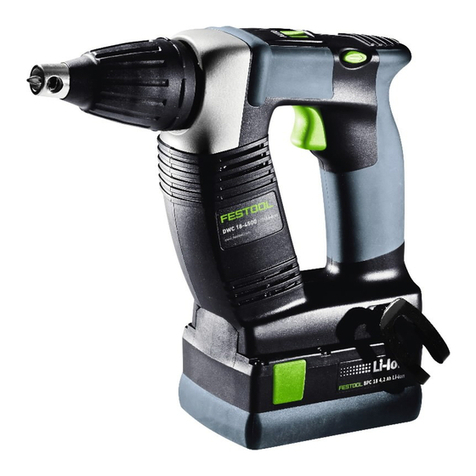
BTI A18 DSS-1 BL 1/2 User manual

Originalbetriebsanleitung
Original instructions
Notice originale
Manual original
Oorspronkelijke gebruiksaanwijzing
Bruksanvisning i original
Πρωτότυπο οδηγιών χρήσης
Orijinal işletme talimatı
Původním návodem k používání
Instrukcjąoryginalną
Originalne pogonske upute
Оригинальное руководство по
эксплуатации
Instrucţiuni de folosire originale
A18 DSS-1 BL 1/2"
Akku-Schlagschrauber
Cordless Impact Screwdriver
Visseuse à Choc sans fil
Atornillador de Impacto a Bateria
Aparafusadora de Impacto a Bateria
Accu-slagmoersleutel
Batteridriven slagskruvdragare
Παλμικο Κατσαβιδι Μπαταριας
Vurmalıakü vidası
Aku rázové utahováky
Klucz udarowy akumulatorowy
Akumulatorsku udarni izvijač
Акк. импульсный гайковерт
Şurubelniţă cu acumulator
457 823 - BTI-A18DSS-1BL12 .indd 1457 823 - BTI-A18DSS-1BL12 .indd 1 18.05.2021 09:34:4918.05.2021 09:34:49

2
8
10
6
457 823 - BTI-A18DSS-1BL12 .indd 2457 823 - BTI-A18DSS-1BL12 .indd 2 18.05.2021 09:34:4918.05.2021 09:34:49

3
4
7
11
9
START
STOP
457 823 - BTI-A18DSS-1BL12 .indd 3457 823 - BTI-A18DSS-1BL12 .indd 3 18.05.2021 09:34:4918.05.2021 09:34:49

4
Vor allen Arbeiten an der
Maschine den
Wechselakku
herausnehmen
Remove the battery pack
before starting any work
on the machine.
Avant tous travaux sur la machine
retirer l’accu interchangeable.
Retire la batería antes de comenzar
cualquier trabajo en la máquina.
Antes de efectuar qualquer
intervenção na máquina retirar o
bloco acumulador.
Voor alle werkzaamheden aan de
machine de akku verwijderen.
Drag ur batteripaket innan arbete
utföres på maskinen.
.
Aletin kendinde bir çalıma yapmadan
önce kartuaküyü çıkarın.
Ped zahájením veškerých prací na
vrtacím šroubováku vyjmout výmnný
akumulátor.
Przed przystpieniem do
jakichkolwiek prac na elektronarzdziu
naley wyj wkadkakumulatorow.
Prije svih radova na stroju izvaditi
bateriju za zamjenu.
B
- .
Îndeprtai acumulatorul înainte de
începerea lucrului pe maina
1
1
2
2
click
457 823 - BTI-A18DSS-1BL12 .indd 4457 823 - BTI-A18DSS-1BL12 .indd 4 18.05.2021 09:34:5018.05.2021 09:34:50
5
78-100 %
55-77 %
33-54 %
10-32 %
< 10 %
457 823 - BTI-A18DSS-1BL12 .indd 5457 823 - BTI-A18DSS-1BL12 .indd 5 18.05.2021 09:34:5018.05.2021 09:34:50
6
457 823 - BTI-A18DSS-1BL12 .indd 6457 823 - BTI-A18DSS-1BL12 .indd 6 18.05.2021 09:34:5018.05.2021 09:34:50
7
START
STOP
457 823 - BTI-A18DSS-1BL12 .indd 7457 823 - BTI-A18DSS-1BL12 .indd 7 18.05.2021 09:34:5018.05.2021 09:34:50

8
457 823 - BTI-A18DSS-1BL12 .indd 8457 823 - BTI-A18DSS-1BL12 .indd 8 18.05.2021 09:34:5018.05.2021 09:34:50
9
LOCK
Handgri(isolierte Grifläche)
Handle (insulated gripping surface)
Poignée (surface de prise isolée)
Empuñadura (superficie de agarre
con aislamiento)
Manípulo (superfície de pega isolada)
Handgreep (geïsoleerd)
Handtag (isolerad greppyta)
(
)
El kulpu (izolasyonlu tutma yüzeyi)
Rukoje(izolovaná uchopovací
plocha)
Uchwyt (z izolowanpowierzchni)
Rukohvat (izolirana površina za
držanje)
(
)
Mâner (suprafa de prindere izolat)
457 823 - BTI-A18DSS-1BL12 .indd 9457 823 - BTI-A18DSS-1BL12 .indd 9 18.05.2021 09:34:5118.05.2021 09:34:51

10
0-1250 0-1950 0-2575 0-1325
0-900 0-2100 0-3100 -
min-1
457 823 - BTI-A18DSS-1BL12 .indd 10457 823 - BTI-A18DSS-1BL12 .indd 10 18.05.2021 09:34:5118.05.2021 09:34:51

11
1
2
457 823 - BTI-A18DSS-1BL12 .indd 11457 823 - BTI-A18DSS-1BL12 .indd 11 18.05.2021 09:34:5118.05.2021 09:34:51

12
A18 DSS-1 BL 1/2"
A18 DSS-1 BL 1/2" 01 000001-999999
....................0-1250 min-1
......................0-900 min-1
......................0-475 Nm
....................0-1950 min-1
....................0-2100 min-1
......................0-610 Nm
....................0-2575 min-1
....................0-3100 min-1
......................0-745 Nm
....................0-1325 min-1
..............................-
...........................47 Nm
.........................745 Nm
........................M22
............... 1/2" (12,7 mm)
...........................18 V
................2,0 ... 3,1 kg
......................-18...+50 °C
.............A18-X, AKKU 18V-X TP
A14,4-18 LG; A14,4-18 LG-2; A 14,4-18 SLG M-A
........................95,4 dB (A)
......................106,4 dB (A)
........................17,4 m/s2
..........................1,5 m/s2
TECHNISCHE DATEN AKKU-SCHLAGSCHRAUBER
Produktionsnummer ..............................................................
Leerlaufdrehzahl.............................................
Schlagzahl......................................................
Drehmoment...................................................
Leerlaufdrehzahl.............................................
Schlagzahl......................................................
Drehmoment...................................................
Leerlaufdrehzahl.............................................
Schlagzahl......................................................
Drehmoment ..................................................
Leerlaufdrehzahl.............................................
Schlagzahl......................................................
Drehmoment ..................................................
Drehmoment max..................................................................
Maximale Schraubengröße / Mutterngröße...........................
Werkzeugaufnahme ..............................................................
Spannung Wechselakku........................................................
Gewicht nach EPTA-Prozedur 01/2014 (2,0 ... 12,0 Ah) .......
Empfohlene Umgebungstemperatur beim Arbeiten...............
Empfohlene Akkutypen..........................................................
Empfohlene Ladegeräte ........................................................
Geräusch/Vibrationsinformation
Messwerte ermittelt entsprechend EN 62841.
Der A-bewertete Geräuschpegel des Gerätes beträgt
typischerweise:
Schalldruckpegel (Unsicherheit K=3dB(A))...........................
Schallleistungspegel (Unsicherheit K=3dB(A))......................
Gehörschutz tragen!
Schwingungsgesamtwerte (Vektorsumme dreier
Richtungen) ermittelt entsprechend EN 62841.
Schwingungsemissionswert ah
Anziehen von Schrauben und Muttern maximaler Größe ..
Unsicherheit K = .................................................................
WARNUNG! Lesen Sie alle Sicherheitshinweise,
Anweisungen, Darstellungen und Spezifikationen für
dieses Elektrowerkzeug. Versäumnisse bei der
Einhaltung der nachstehenden Anweisungen können
elektrischen Schlag, Brand und/oder schwere Verletzungen
verursachen.
SICHERHEITSHINWEISE FÜR
SCHLAGSCHRAUBER
Halten Sie das Gerät an den isolierten Griffflächen,
wenn Sie Arbeiten ausführen, bei denen die Schraube
verborgene Stromleitungen treffen kann. Der Kontakt
der Schraube mit einer spannungsführenden Leitung kann
metallene Geräteteile unter Spannung setzen und zu
einem elektrischen Schlag führen.
Tragen Sie Gehörschutz. Die Einwirkung von Lärm kann
Gehörverlust bewirken.
WEITERE SICHERHEITS- UND ARBEITSHINWEISE
Schutzausrüstung verwenden. Beim Arbeiten mit der
Maschine stets Schutzbrille tragen. Schutzkleidung wie
Staubschutzmaske, Schutzhandschuhe, festes und
DEUTSCH
rutschsicheres Schuhwerk, Helm und Gehörschutz werden
empfohlen.
Beim Arbeiten entstehender Staub ist oft
gesundheitsschädlich und sollte nicht in den Körper
gelangen. Geeignete Staubschutzmaske tragen.
Es dürfen keine Materialien bearbeitet werden, von denen
eine Gesundheitsgefährdung ausgeht (z.B. Asbest).
Beim Blockieren des Einsatzwerkzeuges bitte das Gerät
sofort ausschalten! Schalten Sie das Gerät nicht wieder
ein, solange das Einsatzwerkzeug blockiert ist; hierbei
könnte ein Rückschlag mit hohem Reaktionsmoment
entstehen. Ermitteln und beheben Sie die Ursache für die
Blockierung des Einsatzwerkzeuges unter
Berücksichtigung der Sicherheitshinweise.
Mögliche Ursachen dafür können sein:
• Verkanten im zu bearbeitenden Werkstück
• Durchbrechen des zu bearbeitenden Materials
• Überlasten das Elektrowerkzeuges
Greifen Sie nicht in die laufende Maschine.
WARNUNG
Die angegebenen Schwingungsgesamtwerte und Geräuschemissionswerte wurden nach einem genormten Messverfahren
gemäß EN 62841 gemessen und können für den Vergleich von Elektrowerkzeugen miteinander verwendet werden. Es kann
für eine vorläufige Einschätzung der Belastung verwendet werden.
Der angegebene Schwingungs- und Geräuschemissionspegel repräsentiert die hauptsächlichen Anwendungen des
Elektrowerkzeugs. Wenn allerdings das Elektrowerkzeug für andere Anwendungen, mit abweichenden Einsatzwerkzeugen
oder ungenügender Wartung eingesetzt wird, können sich die Schwingungs- und Geräuschemissionen unterscheiden. Dies
kann deren Wirkung über den gesamten Arbeitszeitraum deutlich erhöhen.
Bei der Abschätzung der Belastung durch Schwingungen und Lärm sollten auch die Zeiten berücksichtigt werden, in denen
das Elektrowerkzeug ausgeschaltet ist oder zwar läuft, aber keine tatsächliche Arbeit verrichtet wird. Dies kann deren
Wirkung über den gesamten Arbeitszeitraum deutlich reduzieren.
Legen Sie zusätzliche Sicherheitsmaßnahmen zum Schutz des Bedieners vor den Auswirkungen von Schwingungen- und /
oder Lärm fest, wie z. B.: Wartung des Werkzeugs und des Zubehörs, Warmhalten der Hände, Organisation der
Arbeitsabläufe.
457 823 - BTI-A18DSS-1BL12 .indd 12457 823 - BTI-A18DSS-1BL12 .indd 12 18.05.2021 09:34:5118.05.2021 09:34:51

13 DEUTSCH
Das Einsatzwerkzeug kann während der Anwendung heiß
werden.
WARNUNG! Verbrennungsgefahr
• bei Werkzeugwechsel
• bei Ablegen des Gerätes
Späne oder Splitter dürfen bei laufender Maschine nicht
entfernt werden.
Beim Arbeiten in Wand, Decke oder Fußboden auf
elektrische Kabel, Gas- und Wasserleitungen achten.
Sichern Sie Ihr Werkstück mit einer Spannvorrichtung. Nicht
gesicherte Werkstücke können schwere Verletzungen und
Beschädigungen verursachen.
Vor allen Arbeiten an der Maschine den Wechselakku
herausnehmen
Verbrauchte Wechselakkus nicht ins Feuer oder in den
Hausmüll werfen. BTI bietet eine umweltgerechte
Alt-Wechselakku-Entsorgung an; bitte fragen Sie Ihren
Außendienstmitarbeiter oder unsere Servicelinie unter
07940 / 141-141.
Wechselakkus nicht zusammen mit Metallgegenständen
aufbewahren (Kurzschlussgefahr).
Wechselakkus des BTI Systems nur mit Ladegeräten des
BTI Systems laden. Keine Akkus aus anderen Systemen
laden.
Wechselakkus und Ladegeräte nicht önen und nur in
trockenen Räumen lagern. Vor Nässe schützen.
Unter extremer Belastung oder extremer Temperatur kann
aus beschädigten Wechselakkus Batterieflüssigkeit
auslaufen. Bei Berührung mit Batterieflüssigkeit sofort mit
Wasser und Seife abwaschen. Bei Augenkontakt sofort
mindestens 10 Minuten gründlich spülen und unverzüglich
einen Arzt aufsuchen.
Warnung! Um die durch einen Kurzschluss verursachte
Gefahr eines Brandes, von Verletzungen oder
Produktbeschädigungen zu vermeiden, tauchen Sie das
Werkzeug, den Wechselakku oder das Ladegerät nicht in
Flüssigkeiten ein und sorgen Sie dafür, dass keine
Flüssigkeiten in die Geräte und Akkus eindringen.
Korrodierende oder leitfähige Flüssigkeiten, wie Salzwasser,
bestimmte Chemikalien und Bleichmittel oder Produkte, die
Bleichmittel enthalten, können einen Kurzschluss
verursachen.
BESTIMMUNGSGEMÄSSE VERWENDUNG
Der Akku-Schlagschrauber ist universell einsetzbar zum
Befestigen und Lösen von Schrauben und Muttern
unabhängig von einem Netzanschluss.
Dieses Gerät darf nur wie angegeben bestimmungsgemäß
verwendet werden.
DREHZAHLEINSTELLUNG
Die Funktion dient zur besseren Kontrolle des
Werkzeugs. Um Schäden am Spannfutter oder der
Arbeitsoberfläche zu vermeiden, schaltet das Gerät
automatisch ab, wenn es ca. 1 Sekunde lang einen
Widerstand erkennt.
CE-KONFORMITÄTSERKLÄRUNG
Wir erklären in alleiniger Verantwortung, dass das unter
„Technische Daten“ beschriebene Produkt mit allen
relevanten Vorschriften der Richtline 2011/65/EU (RoHS),
2014/30/EU, 2006/42/EG und den folgenden harmonisierten
normativen Dokumenten übereinstimmt:
EN 62841-1:2015
EN 62841-2-2:2014
EN IEC 55014-1:2021
EN IEC 55014-2:2021
EN IEC 63000:2018
Ingelfingen, 2021-05-11
Michael Nagel ppa. Martin Mayer-Hagelstein
Managing Director Director Marketing & E-Commerce
Bevollmächtigt die technischen Unterlagen
zusammenzustellen
BTI Befestigungstechnik GmbH & Co. KG
Salzstraße 51
D-74653 Ingelfingen
BEDIENUNG
Hinweis: Es wird empfohlen, nach der Befestigung das
Anzugsdrehmoment immer mit einem
Drehmomentschlüssel zu prüfen.
Das Anzugsdrehmoment wird durch eine Vielzahl von
Faktoren beeinflusst, einschließlich der folgenden.
• Ladezustand der Batterie - Wenn die Batterie entladen ist,
fällt die Spannung ab und das Anzugsdrehmoment
verringert sich.
• Drehzahlen - Die Verwendung des Werkzeugs bei
niedriger Geschwindigkeit führt zu einem geringeren
Anzugsdrehmoment.
• Befestigungsposition - Die Art und Weise, wie Sie das
Werkzeug oder Befestigungselement halten, beeinflusst
das Anzugsdrehmoment.
• Dreh-/Steckeinsatz - Die Verwendung eines Dreh- oder
Steckeinsatzes mit falscher Größe oder die Verwendung
von nicht schlagfestem Zubehör reduziert das
Anzugsdrehmoment.
• Verwendung von Zubehör und Verlängerungen - Je nach
Zubehör oder Verlängerung kann das Anzugsdrehmoment
des Schlagschraubers reduziert werden.
• Schraube/Mutter - Das Anzugsdrehmoment kann je nach
Durchmesser, Länge und Festigkeitsklasse der Schraube/
Mutter variieren.
• Zustand der Befestigungselemente - Verunreinigte,
korrodierte, trockene oder geschmierte
Befestigungselemente können das Anzugsdrehmoment
beinflussen.
• Die zu verschraubenden Teile - Die Festigkeit der zu
verschraubenden Teile und jedes Bauteil dazwischen
(trocken oder geschmiert, weich oder hart, Scheibe,
Dichtung oder Unterlegscheibe) kann das
Anzugsdrehmoment beeinflussen.
EINSCHRAUBTECHNIKEN
Je länger ein Bolzen, eine Schraube oder eine Mutter mit
dem Schlagschrauber belastet wird, desto fester wird sie
angezogen.
Um Beschädigungen der Befestigungsmittel oder
Werkstücke zu vermeiden, vermeiden Sie übermäßige
Schlagdauer.
Seien Sie besonders vorsichtig, wenn Sie auf kleinere
Befestigungsmittel einwirken, da sie weniger Schläge
benötigen, um ein optimales Anzugsdrehmoment zu
erreichen.
Üben Sie mit verschiedenen Befestigungselementen und
merken Sie sich die Zeit, die Sie benötigen, um das
gewünschte Anzugsdrehmoment zu erreichen.
Überprüfen Sie das Anzugsdrehmoment mit einem
Hand-Drehmomentschlüssel.
Wenn das Anzugsdrehmoment zu hoch ist, reduzieren Sie
die Schlagzeit.
Wenn das Anzugsdrehmoment nicht ausreichend ist,
erhöhen Sie die Schlagzeit.
457 823 - BTI-A18DSS-1BL12 .indd 13457 823 - BTI-A18DSS-1BL12 .indd 13 18.05.2021 09:34:5218.05.2021 09:34:52

14
Öl, Schmutz, Rost oder andere Verunreinigungen an den
Gewinden oder unter dem Kopf des Befestigungsmittels
beeinflussen die Höhe des Anzugsdrehmoment.
Das zum Lösen eines Befestigungsmittels erforderliche
Drehmoment beträgt durchschnittlich 75% bis 80% des
Anzugsdrehmoments, abhängig vom Zustand der
Kontaktflächen.
Führen Sie leichte Einschraubarbeiten mit einem relativ
geringen Anzugsdrehmoment aus und verwenden Sie zum
endgültigen Festziehen einen Hand-Drehmomentschlüssel.
AKKUS
Längere Zeit nicht benutzte Wechselakkus vor Gebrauch
nachladen.
Eine Temperatur über 50°C vermindert die Leistung des
Wechselakkus. Längere Erwärmung durch Sonne oder
Heizung vermeiden.
Die Anschlusskontakte an Ladegerät und Wechselakku
sauber halten.
Für eine optimale Lebensdauer müssen nach dem
Gebrauch die Akkus voll geladen werden.
Für eine möglichst lange Lebensdauer sollten die Akkus
nach dem Aufladen aus dem Ladegerät entfernt werden.
Bei Lagerung des Akkus länger als 30 Tage:
Akku bei ca. 27°C und trocken lagern.
Akku bei ca. 30%-50% des Ladezustandes lagern.
Akku alle 6 Monate erneut aufladen.
AKKUÜBERLASTSCHUTZ
Bei Überlastung des Akkus durch sehr hohen
Stromverbrauch, z.B. extrem hohe Drehmomente,
Verklemmen des Bohrers, plötzlichem Stopp oder
Kurzschluss, brummt das Elektrowerkzeug 2 Sekunden
lang und schaltet sich selbsttätig ab.
Zum Wiedereinschalten, den Schalterdrücker loslassen
und dann wieder einschalten.
Unter extremen Belastungen kann sich der Akku stark
erhitzen. In diesem Fall schaltet der Akku ab.
Den Akku dann in das Ladegerät stecken um ihn wieder
aufzuladen und zu aktivieren.
TRANSPORT VON LITHIUM-IONEN-AKKUS
Lithium-Ionen-Akkus fallen unter die gesetzlichen
Bestimmungen zum Gefahrguttransport.
Der Transport dieser Akkus muss unter Einhaltung der
lokalen, nationalen und internationalen Vorschriften und
Bestimmungen erfolgen.
• Verbraucher dürfen diese Akkus ohne Weiteres auf der
Straße transportieren.
• Der kommerzielle Transport von Lithium-Ionen-Akkus
durch Speditionsunternehmen unterliegt den
Bestimmungen des Gefahrguttransports. Die
Versandvorbereitungen und der Transport dürfen
ausschließlich von entsprechend geschulten Personen
durchgeführt werden. Der gesamte Prozess muss
fachmännisch begleitet werden.
Folgende Punkte sind beim Transport von Akkus zu
beachten:
• Stellen Sie sicher, dass die Kontakte geschützt und
isoliert sind, um Kurzschlüsse zu vermeiden.
• Achten Sie darauf, dass der Akkupack innerhalb der
Verpackung nicht verrutschen kann.
• Beschädigte oder auslaufende Akkus dürfen nicht
transportiert werden.
Wenden Sie sich für weitere Hinweise an Ihr
Speditionsunternehmen.
WARTUNG
Nur BTI Zubehör und Ersatzteile verwenden. Bauteile,
deren Austausch nicht beschrieben wurde, bei dem BTI
After Sales Service auswechseln lassen. (BTI
Befestigungstechnik GmbH & Co. KG · After Sales Service
DEUTSCH
· Salzstraße 51 · 74653 Ingelfingen · Tel. 07940 / 141-870,
-872, -873 oder -886 · Fax 07940 / 141-875)
Bei Bedarf kann eine Explosionszeichnung des Geräts
unter Angabe der Maschinenbezeichnung auf der BTI
Homepage unter www.bti.de > Service >
Explosionszeichnungen und Ersatzteillisten > BTI >
Akku-Geräte heruntergeladen werden oder direkt bei BTI
Befestigungstechnik GmbH & Co. KG, After Sales Service,
Salzstraße 51, 74653 Ingelfingen angefordert werden.
SYMBOLE
ACHTUNG! WARNUNG! GEFAHR!
Vor allen Arbeiten an der Maschine den
Wechselakku herausnehmen
Bitte lesen Sie die Gebrauchsanweisung vor
Inbetriebnahme sorgfältig durch.
Elektrogeräte, Batterien/Akkus dürfen nicht
zusammen mit dem Hausmüll entsorgt werden.
Elektrische Geräte und Akkus sind getrennt zu
sammeln und zur umweltgerechten Entsorgung
bei einem Verwertungsbetrieb abzugeben.
Erkundigen Sie sich bei den örtlichen Behörden
oder bei Ihrem Fachhändler nach Recyclinghöfen
und Sammelstellen.
n0Leerlaufdrehzahl
IPM Schlagzahl
VSpannung
Gleichstrom
Europäisches Konformitätszeichen
GARANTIE UND KUNDENDIENST
Jedes Elektrowerkzeug, Ersatzteil oder Zubehörteil wird
vor Verlassen der Fabrik sorgfältig geprüft. Sollten trotzdem
irgendwelche Defekte an Ihrem Werkzeug auftreten, so
senden Sie es bitte an den BTI After Sales Service.
BTI After Sales Service erreichen Sie unter folgenden
Kontaktdaten: BTI Befestigungstechnik GmbH & Co. KG ·
After Sales Service · Salzstraße 51 · 74653 Ingelfingen ·
Tel. 07940 / 141- 874 · Fax 07940 / 141-9874
Die Garantiezeit von 36 Monaten für Werkzeuge bzw. 12
Monate für Batterien und Ladegeräte beginnt mit dem
Kaufdatum, das durch den Original-Kaufbeleg
nachgewiesen werden muss. In dieser Zeit garantieren wir:
• Kostenlose Beseitigung eventueller Störungen
• Kostenlosen Ersatz aller schadhaften Teile
• Kostenlosen und fachmännischen Reparaturservice
Voraussetzung ist, dass es sich um Material- und/oder
Herstellungsfehler handelt. Defekte oder Störungen durch
unsachgemäße Behandlung oder übermäßige
Beanspruchung sind von dieser Garantie ausgeschlossen.
Weiterhin dürfen nur Original-Zubehörteile verwendet
werden, die ausdrücklich von BTI zum Betrieb mit
BTI-Maschinen als geeignet bezeichnet wurden.
Den Standort Ihrer Kundendienst-Werkstatt erfahren Sie
unter der entsprechenden Anschrift auf der Rückseite.
457 823 - BTI-A18DSS-1BL12 .indd 14457 823 - BTI-A18DSS-1BL12 .indd 14 18.05.2021 09:34:5218.05.2021 09:34:52

15
A18 DSS-1 BL 1/2"
A18 DSS-1 BL 1/2" 01 000001-999999
....................0-1250 min-1
......................0-900 min-1
......................0-475 Nm
....................0-1950 min-1
....................0-2100 min-1
......................0-610 Nm
....................0-2575 min-1
....................0-3100 min-1
......................0-745 Nm
....................0-1325 min-1
..............................-
...........................47 Nm
.........................745 Nm
........................M22
............... 1/2" (12,7 mm)
...........................18 V
................2,0 ... 3,1 kg
......................-18...+50 °C
.............A18-X, AKKU 18V-X TP
A14,4-18 LG; A14,4-18 LG-2; A 14,4-18 SLG M-A
........................95,4 dB (A)
......................106,4 dB (A)
........................17,4 m/s2
..........................1,5 m/s2
ENGLISH
TECHNICAL DATA CORDLESS IMPACT SCREWDRIVER
Production code.....................................................................
No-load speed................................................
Impact range ..................................................
Torque ............................................................
No-load speed................................................
Impact range ..................................................
Torque ............................................................
No-load speed................................................
Impact range ..................................................
Torque ............................................................
No-load speed................................................
Impact range ..................................................
Torque ............................................................
Torque max............................................................................
Max. diameter bolt / nut.........................................................
Tool reception ........................................................................
Battery voltage.......................................................................
Weight according EPTA-Procedure 01/2014 (2.0 ... 12.0 Ah).
Recommended ambient operating temperature....................
Recommended battery types.................................................
Recommended charger.........................................................
Noise/vibration information
Measured values determined according to EN 62841.
Typically, the A-weighted noise levels of the tool are:
Sound pressure level (Uncertainty K=3dB(A)) ......................
Sound power level (Uncertainty K=3dB(A))...........................
Wear ear protectors!
Total vibration values (vector sum in the three axes)
determined according to EN 62841.
Vibration emission value ah
Impact tightening of fasteners of the maximum capacity of the tool .
Uncertainty K=....................................................................
WARNING Read all safety warnings, instructions,
illustrations and specifications provided with this
power tool. Failure to follow all instructions listed below
may result in electric shock, fire and/or serious injury.
Save all warnings and instructions for future reference.
IMPACT SCREWDRIVER SAFETY WARNINGS
Hold the power tool by insulated gripping surfaces,
when performing an operation where the fastener may
contact hidden wiring. Fasteners contacting a „live“ wire
may make exposed metal parts of the power tool „live“ and
could give the operator an electric shock.
Wear ear protectors. Exposure to noise can cause
hearing loss.
ADDITIONAL SAFETY AND WORKING INSTRUCTIONS
Use protective equipment. Always wear safety glasses
when working with the machine. The use of protective
clothing is recommended, such as dust mask, protective
gloves, sturdy non-slip footwear, helmet and ear defenders.
The dust produced when using this tool may be harmful to
health. Do not inhale the dust. Wear a suitable dust
protection mask.
Do not machine any materials that present a danger to
health (e.g. asbestos).
Switch the device oimmediately if the insertion tool stalls!
Do not switch the device on again while the insertion tool is
stalled, as doing so could trigger a sudden recoil with a
high reactive force. Determine why the insertion tool stalled
and rectify this, paying heed to the safety instructions.
The possible causes may be:
• it is tilted in the workpiece to be machined
• it has pierced through the material to be machined
• the power tool is overloaded
Do not reach into the machine while it is running.
The insertion tool may become hot during use.
WARNING! Danger of burns
• when changing tools
• when setting the device down
Chips and splinters must not be removed while the
machine is running.
When working in walls ceiling, or floor, take care to avoid
electric cables and gas or waterpipes.
Clamp your workpiece with a clamping device. Unclamped
workpieces can cause severe injury and damage.
WARNING
The vibration and noise emission level given in this information sheet has been measured in accordance with a standardized
test given in EN 62841 and may be used to compare one tool with another. It may be used for a preliminary assessment of
exposure.
The declared vibration and noise emission level represents the main applications of the tool. However if the tool is used for
dierent applications, with dierent accessories or poorly maintained, the vibration and noise emission may dier. This may
significantly increase the exposure level over the total working period.
An estimation of the level of exposure to vibration and noise should also take into account the times when the tool is
switched oor when it is running but not actually doing the job. This may significantly reduce the exposure level over the
total working period.
Identify additional safety measures to protect the operator from the eects of vibration and/or noise such as: maintain the
tool and the accessories, keep the hands warm, organization of work patterns.
457 823 - BTI-A18DSS-1BL12 .indd 15457 823 - BTI-A18DSS-1BL12 .indd 15 18.05.2021 09:34:5218.05.2021 09:34:52

16
Remove the battery pack before starting any work on the
machine.
Do not dispose of used battery packs in the household
refuse or by burning them. BTI oer to retrieve old batteries
to protect our environment; please ask your sales
representative or our service line at 07940 / 141-141.
Do not store the battery pack together with metal objects
(short circuit risk).
Use only System BTI chargers for charging System BTI
battery packs. Do not use battery packs from other systems.
Never break open battery packs and chargers and store
only in dry rooms. Keep dry at all times.
Battery acid may leak from damaged batteries under
extreme load or extreme temperatures. In case of contact
with battery acid wash it oimmediately with soap and
water. In case of eye contact rinse thoroughly for at least 10
minutes and immediately seek medical attention.
Warning! To reduce the risk of fire, personal injury, and
product damage due to a short circuit, never immerse your
tool, battery pack or charger in fluid or allow a fluid to flow
inside them. Corrosive or conductive fluids, such as
seawater, certain industrial chemicals, and bleach or bleach
containing products, etc., can cause a short circuit.
SPECIFIED CONDITIONS OF USE
The cordless impact wrench can be used to tighten and
loosen nuts and bolts wherever no mains connection is
available.
Do not use this product in any other way as stated for
normal use.
RPM SETTING
The function is designed to give the user greater control
in application and reduce damage to the fastener or work
surface by automatically shutting the tool oafter the tool
senses the mechanism impacting for approximately one
second.
EC-DECLARATION OF CONFORMITY
We declare under our sole responsibility that the product
described under “Technical Data” fulfills all the relevant
regulations and the directives 2011/65/EU (RoHS), 2014/30/
EU, 2006/42/EC, and the following harmonized standards
have been used:
EN 62841-1:2015
EN 62841-2-2:2014
EN IEC 55014-1:2021
EN IEC 55014-2:2021
EN IEC 63000:2018
Ingelfingen, 2021-05-11
Michael Nagel ppa. Martin Mayer-Hagelstein
Managing Director Director Marketing & E-Commerce
Authorized to compile the technical file
BTI Befestigungstechnik GmbH & Co. KG
Salzstraße 51
D-74653 Ingelfingen
OPERATION
Note: It is recommended after fastening to always check
the torque with a torque wrench.
The fastening torque is aected by a wide variety of factors
including the following.
• State of battery charge – When the battery is discharged
voltage will drop and the fastening torque will be reduced.
• Operation at speeds – Operating the tool at low speeds
will cause a reduction in fastening torques.
• Fastening position – Holding the tool or the driving
fastener in various angles will aect the torque.
• Drive accessory/socket – Failure to use the correct size
accessory or socket, or a non-impact rated accessory may
cause a reduction in the fastening torque.
• Use of accessories and extensions – Depending on the
accessory or extension fitment can reduce the fastening
force of the impact wrench.
• Bolt/Nut – Fastening torques may dier according to the
diameter of the nut or bolt, the class of nut/bolt and the
length of nut/bolt.
• Condition of the fastener – Contaminated, corroded, dry or
lubricated fasteners may vary the fastening torques.
• Condition and base material – The base material of the
fastener and any component in between the surfaces may
eect the fastening torque (dry or lubricated base, soft or
hard base, disc, seal or washer between fastener and
base material).
IMPACTING TECHNIQUES
The longer a bolt, screw, or nut is impacted, the tighter it will
become.
To help prevent damaging the fasteners or workpieces,
avoid excessive impacting.
Be particularly careful when impacting smaller fasteners
because they require less impacting to reach optimum
torque.
Practice with various fasteners, noting the length of time
required to reach the desired torque.
Check the tightness with a hand-torque wrench.
If the fasteners are too tight, reduce the impacting time.
If they are not tight enough, increase the impacting time.
Oil, dirt, rust or other matter on the threads or under the
head of the fastener aects the degree of tightness.
The torque required to loosen a fastener averages 75% to
80% of the tightening torque, depending on the condition of
the contacting surfaces.
On light gasket jobs, run each fastener down to a relatively
light torque and use a hand torque wrench for final
tightening.
BATTERIES
Battery packs which have not been used for some time
should be recharged before use.
Temperatures in excess of 50°C (122°F) reduce the
performance of the battery pack. Avoid extended exposure
to heat or sunshine (risk of overheating).
The contacts of chargers and battery packs must be kept
clean.
For an optimum life-time, after use, the battery packs have
to be fully charged.
To obtain the longest possible battery life remove the battery
pack from the charger once it is fully charged.
For battery pack storage longer than 30 days:
Store the battery pack where the temperature is below 27°C
and away from moisture
Store the battery packs in a 30% - 50% charged condition
Every six months of storage, charge the pack as normal.
ENGLISH
457 823 - BTI-A18DSS-1BL12 .indd 16457 823 - BTI-A18DSS-1BL12 .indd 16 18.05.2021 09:34:5218.05.2021 09:34:52

17 ENGLISH
BATTERY PACK PROTECTION
In extremely high torque, binding, stalling and short circuit
situations that cause high current draw, the tool will vibrate
for about 2 seconds and then the tool will turn OFF.
To reset, release the trigger.
Under extreme circumstances, the internal temperatur of
the battery could become to high. If this happens, the
battery will shut down.
Place the battery on the charger to charge and reset it.
TRANSPORTING LITHIUM BATTERIES
Lithium-ion batteries are subject to the Dangerous Goods
Legislation requirements.
Transportation of those batteries has to be done in
accordance with local, national and international provisions
and regulations.
• The user can transport the batteries by road without
further requirements.
• Commercial transport of Lithium-Ion batteries by third
parties is subject to Dangerous Goods regulations.
Transport preparation and transport are exclusively to be
carried out by appropriately trained persons and the
process has to be accompanied by corresponding
experts.
When transporting batteries:
• Ensure that battery contact terminals are protected and
insulated to prevent short circuit.
• Ensure that battery pack is secured against movement
within packaging.
• Do not transport batteries that are cracked or leak.
Check with forwarding company for further advice
MAINTENANCE
Use only BTI accessories and spare parts. Components
whose replacement has not been described, can be
exchanged at the BTI after sales service. (BTI
Befestigungstechnik GmbH & Co. KG · After Sales Service
· Salt Road 51 · 74653 Ingelfingen · Tel 07940 / 141-870,
-872, -873 or -886 · Fax 07940 / 141-875)
If needed, an exploded view of the tool can be ordered.
Please state the ten-digit No. as well as the machine type
printed on the label and download the drawing at BTI
Homepage www.bti.de > Service > Explosionszeichnungen
und Ersatzteillisten > BTI > Akku-Geräte or order directly at
BTI Befestigungstechnik GmbH & Co. KG, After Sales
Service, Salzstraße 51, 74653 Ingelfingen.
SYMBOLS
CAUTION! WARNING! DANGER!
Remove the battery pack before starting any
work on the machine.
Please read the instructions carefully before
starting the machine.
Do not dispose electric tools, batteries/
rechargeable batteries together with household
waste material.
Electric tools and batteries that have reached the
end of their life must be collected separately and
returned to an environmentally compatible
recycling facility.
Check with your local authority or retailer for
recycling advice and collection point.
n0No-load speed
IPM Impact range
VVolts
Direct current
European Conformity Mark
GUARANTEE AND GUARANTEE SERVICE
Each tool, spare part or accessory is consistently
checked before being dispatched from the manufacturing
plant. If, despite this fact, there are any defects, please
send the item directly to our Client Services Headquarters
or to the nearest service repair shop of the firm BTI.
BTI after sales service can be reached at the following
contact information: BTI Befestigungstechnik GmbH &
Co. KG · After Sales Service · Salz Straße 51 · 74653
Ingelfingen · Tel 07940/141 - 874 · Fax 07940 / 141-
9874
The warranty period of 36 months for tools and 12
months for batteries and chargers starts on the date
of purchase which must be verified using the original
receipt. During the guarantee period the producer
guarantees:
• free removal of possible defects;
• free replacement of all damaged parts;
• free professional servicing.
The requirement for this is that the problem is a material
and/or manufacturing fault. Defects or faults caused by
incorrect treatment or excessive force are not covered
by the warranty. Furthermore, only original accessory
parts may be used, which BTI has expressly identified as
suitable for the operation with BTI machines.
You can find out the location of your nearest customer
service workshop in the address list at the back of this
document.
457 823 - BTI-A18DSS-1BL12 .indd 17457 823 - BTI-A18DSS-1BL12 .indd 17 18.05.2021 09:34:5318.05.2021 09:34:53

18
A18 DSS-1 BL 1/2"
A18 DSS-1 BL 1/2" 01 000001-999999
....................0-1250 min-1
......................0-900 min-1
......................0-475 Nm
....................0-1950 min-1
....................0-2100 min-1
......................0-610 Nm
....................0-2575 min-1
....................0-3100 min-1
......................0-745 Nm
....................0-1325 min-1
..............................-
...........................47 Nm
.........................745 Nm
........................M22
............... 1/2" (12,7 mm)
...........................18 V
................2,0 ... 3,1 kg
......................-18...+50 °C
.............A18-X, AKKU 18V-X TP
A14,4-18 LG; A14,4-18 LG-2; A 14,4-18 SLG M-A
........................95,4 dB (A)
......................106,4 dB (A)
........................17,4 m/s2
..........................1,5 m/s2
CARACTÉRISTIQUES TECHNIQUES VISSEUSE À CHOC SANS FIL
Numéro de série....................................................................
Vitesse de rotation à vide...............................
Perçage à percussion.....................................
Couple............................................................
Vitesse de rotation à vide...............................
Perçage à percussion.....................................
Couple............................................................
Vitesse de rotation à vide...............................
Perçage à percussion.....................................
Couple............................................................
Vitesse de rotation à vide...............................
Perçage à percussion.....................................
Couple............................................................
Couple max ...........................................................................
Dimension maximale de vis/d'écrou ......................................
Système de fixation ...............................................................
Tension accu interchangeable...............................................
Poids suivant EPTA-Procedure 01/2014 (2,0 ... 12,0 Ah)......
Température conseillée lors du travail...................................
Batteries conseillées..............................................................
Chargeurs de batteries conseillés .........................................
Informations sur le bruit et les vibrations
Valeurs de mesure obtenues conformément à la EN 62841.
La mesure réelle (A) du niveau de bruit de l’outil est
Niveau de pression acoustique (Incertitude K=3dB(A)) ........
Niveau d'intensité acoustique (Incertitude K=3dB(A))...........
Toujours porter une protection acoustique!
Valeurs totales des vibrations (somme vectorielle de trois
sens) établies conformément à EN 62841.
Valeur d’émission vibratoire ah
Vissage à bloc des vis et des écrous de la dimension maximale
Incertitude K= ....................................................................
AVERTISSEMENT! Lire tous les avertissements de
sécurité, les instructions opérationnelles, les
illustrations et les spécifications fournies avec cet outil
électrique. La non observance des instructions
mentionnées ci-dessous peut causer des chocs
électriques, des incendies ou de graves blessures.
INSTRUCTIONS DE SÉCURITÉ POUR VISSEUSE
À CHOC
Tenir l'appareil aux surfaces isolées faisant office de
poignée pendant les travaux au cours desquels la vis
peut toucher des lignes électriques dissimulées. Le
contact de la vis avec un câble qui conduit la tension peut
mettre des parties d'appareil en métal sous tension et
mener à une décharge électrique.
Portez une protection acoustique. L'influence du bruit
peut provoquer la surdité.
AVIS COMPLÉMENTAIRES DE SÉCURITÉ ET
DE TRAVAIL
Utiliser l’équipement de protection. Toujours porter des
lunettes de protection pendant le travail avec la machine. Il
est recommandé de porter des articles de protection, tels
que masque antipoussière, gants de protection,
chaussures tenant bien aux pieds et antidérapantes,
casque et protection acoustique.
Les poussières qui sont dégagées pendant les travaux
sont souvent nocives pour la santé et ne devraient pas
pénétrer dans le corps. Porter un masque de protection
approprié contre les poussières.
Il est interdit de travailler des matériaux dangereux pour la
santé (par ex. amiante).
Désactiver immédiatement le dispositif en cas de blocage !
Ne pas réactiver le dispositif avec l'outil bloqué; il y a le
risque de provoquer un contrecoup avec moment de
réaction élevé. Établir et éliminer la cause du blocage de
l'outil en prêtant attention aux consignes de sécurité.
Les causes possibles sont :
• Encastrement dans la pièce à travailler.
AVERTISSEMENT
Le niveau de vibration et d'émissions sonores indiqué dans cette fiche de données a été mesuré en respect d'une méthode
standard de test selon la norme EN 62841 et peut être utilisé pour comparer les outils entre eux. Il peut être utilisé pour
évaluation préliminaire de l'exposition.
Le niveau de vibration et d'émissions sonores déclaré correspond à l'application principale de l'outil. Cependant, si l'outil est
utilisé pour des applications diérentes, avec diérents accessoires ou est mal entretenu, les vibrations et les émissions
sonores peuvent diérer. Cela peut augmenter considérablement le niveau d'exposition au cours de la période de travail
totale.
Une estimation du niveau d'exposition aux vibrations et au bruit devrait également tenir compte des temps d'arrêt de l'outil
ou des périodes où il est en marche mais n'eectue pas réellement le travail. Cela peut réduire considérablement le niveau
d'exposition au cours de la période de travail totale.
Identifier des mesures de sécurité supplémentaires pour protéger l'opérateur des eets des vibrations et/ou du bruit tels
que : l'entretien de l'outil et des accessoires, le maintien au chaud des mains, l'organisation des processus de travail.
FRANÇAIS
457 823 - BTI-A18DSS-1BL12 .indd 18457 823 - BTI-A18DSS-1BL12 .indd 18 18.05.2021 09:34:5318.05.2021 09:34:53

19
• Le dispositif a traversé le matériau à travailler en le
cassant.
• Le dispositif électrique a été surchargé.
Ne pas approcher les mais de la partie en mouvement de
la machine.
Durant l'utilisation, l'outil peut se surchauer.
AVERTISSEMENT! Danger de brûlures
• durant le remplacement de l‘outil
• durant la dépose de l‘outil
Ne jamais enlever les copeaux ni les éclats lorsque la
machine est en marche.
Lors du perçage dans les murs, les plafonds ou les
planchers, toujours faire attention aux câbles électriques et
aux conduites de gaz et d'eau.
Fixer fermement la pièce en exécution à l'aide d'un
dispositif de serrage. Des pièce en exécution non
fermement fixées peuvent provoquer des dommages et
des lésions graves.
Avant tous travaux sur la machine retirer l’accu
interchangeable.
Ne jetez pas dans le feu ou dans votre poubelle les
batteries épuisées. BTI propose un traitement écologique
des batteries épuisées; adressez-vous à votre agent ou à
notre numéro d'assistance 07940 / 141-141.
Ne pas conserver les accus interchangeables avec des
objets métalliques (risque de court-circuit)
Ne chargez les batteries du système BTI qu'à l'aide d'un
chargeur de batteries du système BTI. Ne pas charger de
batteries d'autres systèmes.
Ne pas ouvrir les accus interchangeables et les chargeurs
et ne les stocker que dans des locaux secs. Les protéger
contre l’humidité.
En cas de conditions ou températures extrêmes, du liquide
caustique peut s’échapper d’un accu interchangeable
endommagé. En cas de contact avec le liquide caustique
de la batterie, laver immédiatement avec de l’eau et du
savon. En cas de contact avec les yeux, rincer
soigneusement avec de l’eau et consulter immédiatement
un médecin.
Avertissement! Pour réduire le risque d‘incendie, de
blessures corporelles et de dommages causés par un
court-circuit, ne jamais immerger l‘outil, le bloc-piles ou le
chargeur dans un liquide ou laisser couler un fluide à
l‘intérieur de celui-ci. Les fluides corrosifs ou conducteurs,
tels que l‘eau de mer, certains produits chimiques
industriels, les produits de blanchiment ou de blanchiment,
etc., peuvent provoquer un court-circuit.
UTILISATION CONFORME AUX PRESCRIPTIONS
La visseuse á percussion à accu peut être utilisée de
manière universelle pour visser et dévisser des vis et des
écrous, indépendamment d’une prise de réseau.
Comme déjà indiqué, cette machine n’est conçue que pour
être utilisée conformément aux prescriptions.
SÉLECTION VITESSE
La fonction permet de mieux contrôler l'outil. Pour éviter
des dommages au mandrin ou à la surface de travail, le
dispositif s'arrête automatiquement s'il relève une
résistance pour env. 1 seconde.
DÉCLARATION CE DE CONFORMITÉ
Nous déclarons sous notre propre responsabilité que le
produit décrit aux "Données techniques" est conforme à
toutes les dispositions des directives 2011/65/EU (RoHS),
2014/30/UE, 2006/42/CE et des documents normatifs
harmonisés suivants:
EN 62841-1:2015
EN 62841-2-2:2014
EN IEC 55014-1:2021
EN IEC 55014-2:2021
EN IEC 63000:2018
Ingelfingen, 2021-05-11
Michael Nagel ppa. Martin Mayer-Hagelstein
Managing Director Director Marketing & E-Commerce
Autorisé à compiler la documentation technique.
BTI Befestigungstechnik GmbH & Co. KG
Salzstraße 51
D-74653 Ingelfingen
UTILISATION
Remarque : il est recommandé de toujours vérifier le
couple de serrage au moyen d’une clé
dynamométrique après la fixation.
Le couple de serrage est influencé par un certain nombre
de facteurs, dont les suivants :
• État de la batterie - Lorsque la batterie est déchargée, la
tension chute et le couple de serrage est réduit.
• Vitesse de rotation - L’utilisation de l’outil à vitesse
réduite entraîne une réduction du couple de serrage.
• Position lors de la fixation - La façon dont vous tenez
l’outil ou l’élément de fixation aecte le couple de
serrage.
• Insert rotatif/enfichable - L’utilisation d’un insert rotatif/
enfichable d’une taille incorrecte ou d’accessoires ne
résistant pas aux chocs réduit le couple de serrage.
• Utilisation d’accessoires et de rallonges - En fonction des
accessoires ou des rallonges utilisés, le couple de
serrage de la visseuse à percussions peut être réduit.
• Vis/écrou - Le couple de serrage peut varier selon le
diamètre, la longueur et la classe de résistance de la vis/
de l’écrou.
• État des éléments de fixation - Des éléments de fixation
encrassés, corrodés, secs ou lubrifiés peuvent influencer
le couple de serrage.
• Les pièces à visser - La solidité des pièces à visser et
tout composant se trouvant entre celles-ci (sec ou
lubrifié, souple ou dur, plaquette, joint ou rondelle) peut
influencer le couple de serrage.
TECHNIQUES DE SERRAGE
Le couple de serrage du boulon, de la vis ou de l’écrou est
proportionnel à la durée de la percussion.
Pour éviter d’endommager les fixations ou le matériau,
limitez la durée de la percussion.
Afin d’obtenir un couple de serrage optimal, soyez
particulièrement prudent lorsque vous serrez des fixations
de petit calibre qui requièrent moins de percussion.
Pratiquez le serrage à percussion avec divers types de
fixations afin d’apprendre quelle est la durée de percussion
nécessaire pour obtenir le couple désiré.
Vérifiez le serrage à l’aide d’une clé dynamométrique
manuelle.
Si la fixation est trop serrée, réduisez la durée de
percussion.
Si la fixation n’est pas serrée à fond, augmentez la durée
de percussion.
L’huile, la poussière ou d’autres saletés sur le filetage ou
sous la tête de la fixation peuvent aecter le couple de
serrage.
Le couple nécessaire pour desserrer une fixation est, en
moyenne, 75 % à 80 % du couple nécessaire pour la
serrer, selon l’état des surfaces en contact.
FRANÇAIS
457 823 - BTI-A18DSS-1BL12 .indd 19457 823 - BTI-A18DSS-1BL12 .indd 19 18.05.2021 09:34:5318.05.2021 09:34:53

20
Eectuez les simples tâches de vissage en exerçant un
couple de serrage relativement faible et terminez le serrage
à la main à l’aide de la clé dynamométrique.
ACCUS
Recharger les accus avant utilisation après une longue
période de non utilisation.
Une température supérieure à 50°C amoindrit la capacité
des accus. Eviter les expositions prolongées au soleil ou
au chauage.
Tenir propres les contacts des accus et des chargeurs.
Après l‘usage, les accus doivent être chargés entièrement
pour une durée de vie optimale.
Pour une plus longue durée de vie, enlever les batteries du
chargeur de batterie quand celles-ci seront chargées.
En cas d‘entreposage de la batterie pour plus de 30 jours:
Entreposer la batterie à 27°C environ dans un endroit sec.
Entreposer la batterie avec une charge d‘environ 30% -
50%.
Recharger la batterie tous les 6 mois.
PROTECTION DE L’ACCU CONTRE LES SURCHARGES
En cas de surcharge de l’accu suite à une consommation
de courant très élevée, par exemple des couples
extrêmement hauts, un coincement du foret, un arrêt
soudain ou un court-circuit, l’outil électrique se met à
bourdonner pendant 2 secondes et s’éteint
automatiquement.
Pour le remettre en marche, il faut relâcher le poussoir de
commutateur, puis l’enclencher à nouveau.
Il se peut que l’accu s’échaue fortement s’il est soumis à
des sollicitations extrêmes. Dans ce cas, il se déconnecte.
Mettre alors l‘accu en place dans le chargeur pour le
recharger et l‘activer.
TRANSPORT DE BATTERIES LITHIUM-ION
Les batteries lithium-ion sons soumises aux dispositions
législatives concernant le transport de produits dangereux.
Le transport de ces batteries devra s'eectuer dans le
respect des dispositions et des normes locales, nationales
et internationales.
• Les utilisateurs peuvent transporter ces batteries sans
restrictions.
• Le transport commercial de batteries lithium-ion est réglé
par les dispositions concernant le transport de produits
dangereux. La préparation au transport et le transport
devront être eectués uniquement par du personnel
formé de façon adéquate. Tout le procédé devra être
géré d‘une manière professionnelle.
Durant le transport de batteries il faut respecter les
consignes suivantes :
• S‘assurer que les contacts soient protégés et isolés en
vue d‘éviter des courts-circuits.
• S‘assurer que le groupe de batteries ne puisse pas se
déplacer à l‘intérieur de son emballage.
• Des batteries endommagées ou des batteries perdant du
liquide ne devront pas être transportées.
Pour tout renseignement complémentaire veuillez vous
adresser à votre transporteur professionnel.
ENTRETIEN
N'employez que des accessoires et des pièces détachées
BTI. Ces composants dont on n'a pas décrit le
remplacement doivent être remplacés par BTI After Sales
Service. BTI Befestigungstechnik GmbH & Co. KG · After
Sales Service · Salzstraße 51 · 74653 Ingelfingen · Tel.
07940 / 141-886 · Fax 07940 / 141-875
En cas de besoin il est possible de demander à BTI un
dessin éclaté du dispositif en indiquant la dénomination de
la machine imprimée sur la plaquette de puissance.
SYMBOLES
ATTENTION! AVERTISSEMENT! DANGER!
Avant tous travaux sur la machine retirer l’accu
interchangeable.
Veuillez lire avec soin le mode d‘emploi avant la
mise en service
Les dispositifs électriques, les batteries et les
batteries rechargables ne sont pas à éliminer
dans les déchets ménagers.
Les dispositifs électriques et les batteries sont à
collecter séparément et à remettre à un centre
de recyclage en vue de leur élimination dans le
respect de l‘environnement.
S‘adresser aux autorités locales ou au détaillant
spécialisé en vue de connaître l‘emplacement
des centres de recyclage et des points de
collecte.
n0Vitesse de rotation à vide
IPM Fréquence de percussion
VVoltage
Courant continu
Marque de conformité européenne
LA GARANTIE ET LE SERVICE POUR LE CLIENT
Tout dispositif électrique, pièce détachée ou accessoire est
contrôlé soigneusement en usine avant son expédition.
Malgré tout cela si votre dispositif présente des défauts,
nous vous demandons de l‘envoyer à BTI After Sales
Service.
On pourra contacter BTI After Sales Service des façons
suivantes: BTI Befestigungstechnik GmbH & Co. KG · After
Sales Service · Salzstraße 51 · 74653 Ingelfingen · Tel.
07940 / 141- 874 · Fax 07940 / 141-9874
La période de garantie de 36 mois pour les outils et de 12
mois pour batteries et chargeurs partira de la date d’achat
qui devra être documentée à l’aide du ticket de caisse
original. Pendant le délai de garantie le producteur garanti:
• Réparation gratuite des défauts éventuels
• Echange gratuit de toutes les pieces endommagées
• Le service gratuit et professionnel
Condition impérative est qu’il s’agisse d’un défaut de
matériau o de fabrication. Les défauts ou les anomalies
causés par une utilisation incorrecte ou par une sollicitation
excessive sont exclus de la présente garantie. De plus,
seules des pièces accessoires d‘origine sont utilisées,
pièces que BTI a expressément identifiées comme étant
appropriées pour fonctionner sur les machines BTI.
Vous trouvez l‘endroit où se trouve votre atelier de
réparation pour le service après-vente avec l‘adresse
correspondante au verso de la notice originale
d‘instruction.
FRANÇAIS
457 823 - BTI-A18DSS-1BL12 .indd 20457 823 - BTI-A18DSS-1BL12 .indd 20 18.05.2021 09:34:5418.05.2021 09:34:54
Table of contents
Languages:
Other BTI Power Screwdriver manuals

BTI
BTI A18 DSS 1/2 User manual

BTI
BTI Profiline BTI-BS 6-25 E User manual

BTI
BTI A18 DSS-2 1/4 User manual

BTI
BTI PROFILINE BTI-ABS 12 VE User manual

BTI
BTI Profiline BTI-AS 10,8 V LI User manual

BTI
BTI A18 DSS 1/2 User manual

BTI
BTI PROFILINE BTI-BS 6-25 TE User manual

BTI
BTI A-S2 10,8V LI S User manual

BTI
BTI Profiline A-SBS 36V LI User manual