Press P2
Motor Response:
Press DOWN
Motor Response:
Press DOWN
Motor Response:
Press P2
Motor Response:
Press UP
Motor Response:
Press UP
Motor Response:
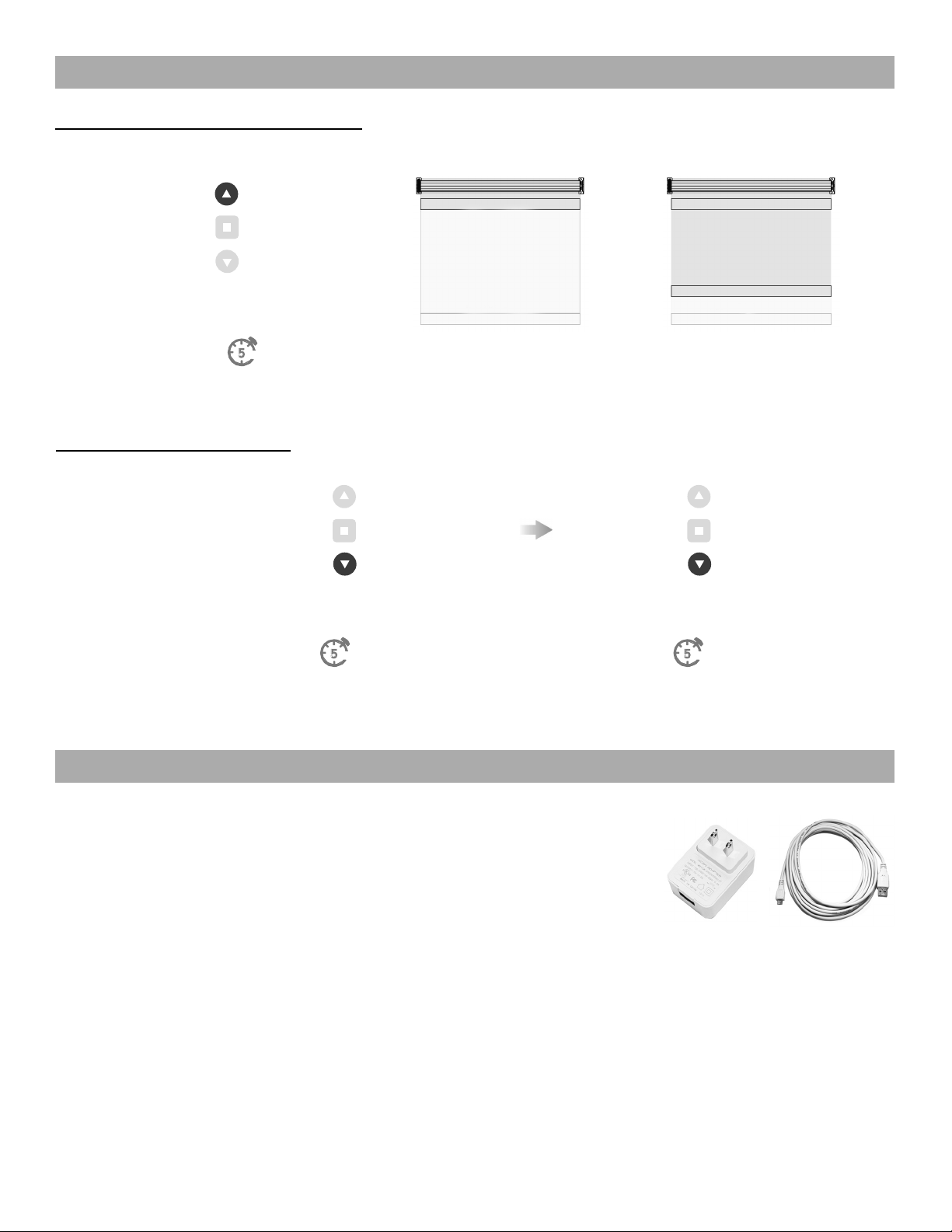
Turn Soft Stop ON
Motor must be in fastest speed to turn Soft Stop ON.
Turn Soft Stop ON
Motor must be in fastest speed to turn Soft Stop ON.
Turn Soft Stop OFF
Motor must be in slowest speed to turn Soft Stop OFF.
Turn Soft Stop OFF
Motor must be in slowest speed to turn Soft Stop OFF.
7
Using P2 Button on existing controller to add a new controller or channel
Using a pre-existing controller to add or delete a controller or channel
A = Existing controller or channel (to keep)
B = Controller or channel to add or remove
A = Existing controller or channel (to keep)
B = Controller or channel to add or remove
Press P2 on
controller A.
Press P2 on
controller A.
Press P2 on
controller A.
Press P2 on
controller A.
Press P2 on the
controller B to remove
it.
Press STOP on an new
controller to add it.
Motor Response
Motor Response
Motor Response
Motor Response
Motor Response
Motor Response
7 CONTROLLERS AND CHANNELS
Consult user manual for your controller or sensor
Consult user manual for your controller or sensor
IMPORTANT
IMPORTANT
.
Pair motor with controller
Check motor direction
Consult user manual for your
controller for information on
selecting channel.
Damage to shade may occur when operating motor prior to
setting limits. Attention should be given.
Reversing motor direction using this method is only possible
during initial set-up
Hold P1 button on
motor head.
To check travel direction of shade, press UP or
DOWN on controller.
Quick Press = Step
Long Press = Continuous Travel
To reverse shade direction, hold both UP and
DOWN.
Until the motor responds.
Select channel on
controller.
Hold STOP on
controller.
Approx.
Approx.
Motor Response
Motor Response
Motor Response
Motor is now in step mode and ready for setting limits
IMPORTANT
IMPORTANT
IMPORTANT
5 INITIAL SET UP
OR
JOG
BEEP
Using P2 Button on existing controller to add a new controller or channel
Using a pre-existing controller to add or delete a controller or channel
A = Existing controller or channel (to keep)
B = Controller or channel to add or remove
A = Existing controller or channel (to keep)
B = Controller or channel to add or remove
Press P2 on
controller A.
Press P2 on
controller A.
Press P2 on
controller A.
Press P2 on
controller A.
Press P2 on the
controller B to remove
it.
Press STOP on an new
controller to add it.
Motor Response
Motor Response
Motor Response
Motor Response
Motor Response
Motor Response
7 CONTROLLERS AND CHANNELS
Consult user manual for your controller or sensor
Consult user manual for your controller or sensor
IMPORTANT
IMPORTANT
.
Pair motor with controller
Check motor direction
Consult user manual for your
controller for information on
selecting channel.
Damage to shade may occur when operating motor prior to
setting limits. Attention should be given.
Reversing motor direction using this method is only possible
during initial set-up
Hold P1 button on
motor head.
To check travel direction of shade, press UP or
DOWN on controller.
Quick Press = Step
Long Press = Continuous Travel
To reverse shade direction, hold both UP and
DOWN.
Until the motor responds.
Select channel on
controller.
Hold STOP on
controller.
Approx.
Approx.
Motor Response
Motor Response
Motor Response
Motor is now in step mode and ready for setting limits
IMPORTANT
IMPORTANT
IMPORTANT
5 INITIAL SET UP
OR
.
Pair motor with controller
Check motor direction
Consult user manual for your
controller for information on
selecting channel.
Damage to shade may occur when operating motor prior to
setting limits. Attention should be given.
Reversing motor direction using this method is only possible
during initial set-up
Hold P1 button on
motor head.
To check travel direction of shade, press UP or
DOWN on controller.
Quick Press = Step
Long Press = Continuous Travel
To reverse shade direction, hold both UP and
DOWN.
Until the motor responds.
Select channel on
controller.
Hold STOP on
controller.
Approx.
Approx.
Motor Response
Motor Response
Motor Response
Motor is now in step mode and ready for setting limits
IMPORTANT
IMPORTANT
IMPORTANT
5 INITIAL SET UP
OR
.
Pair motor with controller
Check motor direction
Consult user manual for your
controller for information on
selecting channel.
Damage to shade may occur when operating motor prior to
setting limits. Attention should be given.
Reversing motor direction using this method is only possible
during initial set-up
Hold P1 button on
motor head.
To check travel direction of shade, press UP or
DOWN on controller.
Quick Press = Step
Long Press = Continuous Travel
To reverse shade direction, hold both UP and
DOWN.
Until the motor responds.
Select channel on
controller.
Hold STOP on
controller.
Approx.
Approx.
Motor Response
Motor Response
Motor Response
Motor is now in step mode and ready for setting limits
IMPORTANT
IMPORTANT
IMPORTANT
5 INITIAL SET UP
OR
JOG
BEEP
.
Pair motor with controller
Check motor direction
Consult user manual for your
controller for information on
selecting channel.
Damage to shade may occur when operating motor prior to
setting limits. Attention should be given.
Reversing motor direction using this method is only possible
during initial set-up
Hold P1 button on
motor head.
To check travel direction of shade, press UP or
DOWN on controller.
Quick Press = Step
Long Press = Continuous Travel
To reverse shade direction, hold both UP and
DOWN.
Until the motor responds.
Select channel on
controller.
Hold STOP on
controller.
Approx.
Approx.
Motor Response
Motor Response
Motor Response
Motor is now in step mode and ready for setting limits
IMPORTANT
IMPORTANT
IMPORTANT
5 INITIAL SET UP
OR
JOG
BEEP
.
Pair motor with controller
Check motor direction
Consult user manual for your
controller for information on
selecting channel.
Damage to shade may occur when operating motor prior to
setting limits. Attention should be given.
Reversing motor direction using this method is only possible
during initial set-up
Hold P1 button on
motor head.
To check travel direction of shade, press UP or
DOWN on controller.
Quick Press = Step
Long Press = Continuous Travel
To reverse shade direction, hold both UP and
DOWN.
Until the motor responds.
Select channel on
controller.
Hold STOP on
controller.
Approx.
Approx.
Motor Response
Motor Response
Motor Response
Motor is now in step mode and ready for setting limits
IMPORTANT
IMPORTANT
IMPORTANT
5 INITIAL SET UP
OR
JOG
EXT. BEEP
Press P2
Motor Response:
Press DOWN
Motor Response:
Press DOWN
Motor Response:
Press P2
Motor Response:
Press UP
Motor Response:
Press UP
Motor Response:
Using P2 Button on existing controller to add a new controller or channel
Using a pre-existing controller to add or delete a controller or channel
A = Existing controller or channel (to keep)
B = Controller or channel to add or remove
A = Existing controller or channel (to keep)
B = Controller or channel to add or remove
Press P2 on
controller A.
Press P2 on
controller A.
Press P2 on
controller A.
Press P2 on
controller A.
Press P2 on the
controller B to remove
it.
Press STOP on an new
controller to add it.
Motor Response
Motor Response
Motor Response
Motor Response
Motor Response
Motor Response
7 CONTROLLERS AND CHANNELS
Consult user manual for your controller or sensor
Consult user manual for your controller or sensor
IMPORTANT
IMPORTANT
.
Pair motor with controller
Check motor direction
Consult user manual for your
controller for information on
selecting channel.
Damage to shade may occur when operating motor prior to
setting limits. Attention should be given.
Reversing motor direction using this method is only possible
during initial set-up
Hold P1 button on
motor head.
To check travel direction of shade, press UP or
DOWN on controller.
Quick Press = Step
Long Press = Continuous Travel
To reverse shade direction, hold both UP and
DOWN.
Until the motor responds.
Select channel on
controller.
Hold STOP on
controller.
Approx.
Approx.
Motor Response
Motor Response
Motor Response
Motor is now in step mode and ready for setting limits
IMPORTANT
IMPORTANT
IMPORTANT
5 INITIAL SET UP
OR
.
Pair motor with controller
Check motor direction
Consult user manual for your
controller for information on
selecting channel.
Damage to shade may occur when operating motor prior to
setting limits. Attention should be given.
Reversing motor direction using this method is only possible
during initial set-up
Hold P1 button on
motor head.
To check travel direction of shade, press UP or
DOWN on controller.
Quick Press = Step
Long Press = Continuous Travel
To reverse shade direction, hold both UP and
DOWN.
Until the motor responds.
Select channel on
controller.
Hold STOP on
controller.
Approx.
Approx.
Motor Response
Motor Response
Motor Response
Motor is now in step mode and ready for setting limits
IMPORTANT
IMPORTANT
IMPORTANT
5 INITIAL SET UP
OR
.
Pair motor with controller
Check motor direction
Consult user manual for your
controller for information on
selecting channel.
Damage to shade may occur when operating motor prior to
setting limits. Attention should be given.
Reversing motor direction using this method is only possible
during initial set-up
Hold P1 button on
motor head.
To check travel direction of shade, press UP or
DOWN on controller.
Quick Press = Step
Long Press = Continuous Travel
To reverse shade direction, hold both UP and
DOWN.
Until the motor responds.
Select channel on
controller.
Hold STOP on
controller.
Approx.
Approx.
Motor Response
Motor Response
Motor Response
Motor is now in step mode and ready for setting limits
IMPORTANT
IMPORTANT
IMPORTANT
5 INITIAL SET UP
OR
JOG
BEEP
.
Pair motor with controller
Check motor direction
Consult user manual for your
controller for information on
selecting channel.
Damage to shade may occur when operating motor prior to
setting limits. Attention should be given.
Reversing motor direction using this method is only possible
during initial set-up
Hold P1 button on
motor head.
To check travel direction of shade, press UP or
DOWN on controller.
Quick Press = Step
Long Press = Continuous Travel
To reverse shade direction, hold both UP and
DOWN.
Until the motor responds.
Select channel on
controller.
Hold STOP on
controller.
Approx.
Approx.
Motor Response
Motor Response
Motor Response
Motor is now in step mode and ready for setting limits
IMPORTANT
IMPORTANT
IMPORTANT
5 INITIAL SET UP
OR
JOG
BEEP
.
Pair motor with controller
Check motor direction
Consult user manual for your
controller for information on
selecting channel.
Damage to shade may occur when operating motor prior to
setting limits. Attention should be given.
Reversing motor direction using this method is only possible
during initial set-up
Hold P1 button on
motor head.
To check travel direction of shade, press UP or
DOWN on controller.
Quick Press = Step
Long Press = Continuous Travel
To reverse shade direction, hold both UP and
DOWN.
Until the motor responds.
Select channel on
controller.
Hold STOP on
controller.
Approx.
Approx.
Motor Response
Motor Response
Motor Response
Motor is now in step mode and ready for setting limits
IMPORTANT
IMPORTANT
IMPORTANT
5 INITIAL SET UP
OR
JOG
BEEP
Using P2 Button on existing controller to add a new controller or channel
Using a pre-existing controller to add or delete a controller or channel
A = Existing controller or channel (to keep)
B = Controller or channel to add or remove
A = Existing controller or channel (to keep)
B = Controller or channel to add or remove
Press P2 on
controller A.
Press P2 on
controller A.
Press P2 on
controller A.
Press P2 on
controller A.
Press P2 on the
controller B to remove
it.
Press STOP on an new
controller to add it.
Motor Response
Motor Response
Motor Response
Motor Response
Motor Response
Motor Response
7 CONTROLLERS AND CHANNELS
Consult user manual for your controller or sensor
Consult user manual for your controller or sensor
IMPORTANT
IMPORTANT
.
Pair motor with controller
Check motor direction
Consult user manual for your
controller for information on
selecting channel.
Damage to shade may occur when operating motor prior to
setting limits. Attention should be given.
Reversing motor direction using this method is only possible
during initial set-up
Hold P1 button on
motor head.
To check travel direction of shade, press UP or
DOWN on controller.
Quick Press = Step
Long Press = Continuous Travel
To reverse shade direction, hold both UP and
DOWN.
Until the motor responds.
Select channel on
controller.
Hold STOP on
controller.
Approx.
Approx.
Motor Response
Motor Response
Motor Response
Motor is now in step mode and ready for setting limits
IMPORTANT
IMPORTANT
IMPORTANT
5 INITIAL SET UP
OR
.
Pair motor with controller
Check motor direction
Consult user manual for your
controller for information on
selecting channel.
Damage to shade may occur when operating motor prior to
setting limits. Attention should be given.
Reversing motor direction using this method is only possible
during initial set-up
Hold P1 button on
motor head.
To check travel direction of shade, press UP or
DOWN on controller.
Quick Press = Step
Long Press = Continuous Travel
To reverse shade direction, hold both UP and
DOWN.
Until the motor responds.
Select channel on
controller.
Hold STOP on
controller.
Approx.
Approx.
Motor Response
Motor Response
Motor Response
Motor is now in step mode and ready for setting limits
IMPORTANT
IMPORTANT
IMPORTANT
5 INITIAL SET UP
OR
.
Pair motor with controller
Check motor direction
Consult user manual for your
controller for information on
selecting channel.
Damage to shade may occur when operating motor prior to
setting limits. Attention should be given.
Reversing motor direction using this method is only possible
during initial set-up
Hold P1 button on
motor head.
To check travel direction of shade, press UP or
DOWN on controller.
Quick Press = Step
Long Press = Continuous Travel
To reverse shade direction, hold both UP and
DOWN.
Until the motor responds.
Select channel on
controller.
Hold STOP on
controller.
Approx.
Approx.
Motor Response
Motor Response
Motor Response
Motor is now in step mode and ready for setting limits
IMPORTANT
IMPORTANT
IMPORTANT
5 INITIAL SET UP
OR
JOG
BEEP
.
Pair motor with controller
Check motor direction
Consult user manual for your
controller for information on
selecting channel.
Damage to shade may occur when operating motor prior to
setting limits. Attention should be given.
Reversing motor direction using this method is only possible
during initial set-up
Hold P1 button on
motor head.
To check travel direction of shade, press UP or
DOWN on controller.
Quick Press = Step
Long Press = Continuous Travel
To reverse shade direction, hold both UP and
DOWN.
Until the motor responds.
Select channel on
controller.
Hold STOP on
controller.
Approx.
Approx.
Motor Response
Motor Response
Motor Response
Motor is now in step mode and ready for setting limits
IMPORTANT
IMPORTANT
IMPORTANT
5 INITIAL SET UP
OR
JOG
BEEP
.
Pair motor with controller
Check motor direction
Consult user manual for your
controller for information on
selecting channel.
Damage to shade may occur when operating motor prior to
setting limits. Attention should be given.
Reversing motor direction using this method is only possible
during initial set-up
Hold P1 button on
motor head.
To check travel direction of shade, press UP or
DOWN on controller.
Quick Press = Step
Long Press = Continuous Travel
To reverse shade direction, hold both UP and
DOWN.
Until the motor responds.
Select channel on
controller.
Hold STOP on
controller.
Approx.
Approx.
Motor Response
Motor Response
Motor Response
Motor is now in step mode and ready for setting limits
IMPORTANT
IMPORTANT
IMPORTANT
5 INITIAL SET UP
OR
JOG
EXT. BEEP
Soft Stop Conguration
Using P2 Button on existing controller to add a new controller or channel
Using a pre-existing controller to add or delete a controller or channel
A = Existing controller or channel (to keep)
B = Controller or channel to add or remove
A = Existing controller or channel (to keep)
B = Controller or channel to add or remove
Press P2 on
controller A.
Press P2 on
controller A.
Press P2 on
controller A.
Press P2 on
controller A.
Press P2 on the
controller B to remove
it.
Press STOP on an new
controller to add it.
Motor Response
Motor Response
Motor Response
Motor Response
Motor Response
Motor Response
7 CONTROLLERS AND CHANNELS
Consult user manual for your controller or sensor
Consult user manual for your controller or sensor
IMPORTANT
IMPORTANT
Soft Stop Conguration