Page. 3
CONTENTS
5mm Allen Key
1Tension Lock
2Spanner Tool
3
SECTION A | SYSTEM DETAILS 3
OVERVIEW.......... ......................................................................................................................................................... 3
SYSTEM OPTIONS ............................................................................................................................................4
BOM & CUTTING LIST ............................................................................................................................................ 5
SECTION B | PREPARATION 5
FABRIC PREPARATION ............................................................................................................................. 5
SECTION C | ASSEMBLY 6
IDLER ASSEMBLY ............................................................................................................................................6
CONTROL ASSEMBLY ............................................................................................................................................6
SECTION D | PRE-TENSION 7
PRE-TENSIONING ............................................................................................................................................ 7
SPRING CAPACITY CHART | 420GSM | 1.5” TUBE ................................................................................. 8
SPRING CAPACITY CHART | 350GSM | 1.5” TUBE .................................................................................9
SPRING CAPACITY CHART | 220GSM | 1.5” TUBE ............................................................................... 10
SPRING CAPACITY CHART | 155GSM | 1.5” TUBE .................................................................................11
SPRING CAPACITY CHART | 420GSM | 2” TUBE ................................................................................12
SPRING CAPACITY CHART | 350GSM | 2” TUBE ................................................................................13
SPRING CAPACITY CHART | 220GSM | 2” TUBE ............................................................................... 14
SPRING CAPACITY CHART | 155GSM | 2” TUBE ................................................................................15
SECTION E | PREPARE & PACK ASSEMBLIES FOR INSTALLATION 16
OPEN SYSTEM... ........................................................................................................................................................16
CASSETTE SYSTEM ...........................................................................................................................................16
SECTION F | INSTALLATION 17
SHADE INSTALLATION...........................................................................................................................................17
PRE-TENSION CHECKS ............................................................................................................................17
ADD OR REMOVE PRE-TURNS .............................................................................................................18
SET LIMITS .......... ........................................................................................................................................................18
SECTION G | TROUBLESHOOTING 19
Easy Spring Air Assembly and Installation Manual | v1.2 | October 2023
©Copyright All Rights Reserved Rollease Acmeda
DISCLAIMER
INTRODUCTION
This Assembly and Installation manual for Easy Spring Air System has been produced by Rollease Acmeda to supply the necessary information for the safe and
correct assembly of Easy Spring Air System.
DISCLAIMER
Rollease Acmeda has used reasonable care in preparing the information included in this document, but makes no representations or warranties as to the
completeness or accuracy of the information. Information is supplied upon the condition that the persons receiving the information will make their own
determination as to its suitability for their purposes prior to use. Rollease Acmeda assumes no liability whatsoever for any damages incurred by you resulting
from errors in or omissions from the information included herein. Rollease Acmeda reserves the right to make changes without further notice to any products to
improve reliability, function or design.
COPYRIGHT
COPYRIGHT © ROLLEASE ACMEDA
All rights are reserved. No part of this document may be reproduced or utilised in any means, by any means, electronic or mechanical including photocopying,
recordings, or by any information storage or retrieval system, without the express permission from Rollease Acmeda.
SECTION A | SYSTEM DETAILS
GENERAL SCHEMATIC
OVERVIEW
1A
1G
3
5
6
1B
1C
1D
2A
2B
4A
4A
4B
4B
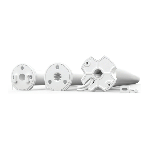
1. CONTROL:
• A - Easy Spring Air Micro
• B - Easy Spring Air Mini
• C - Easy Spring Air Small
• D - Easy Spring Air Light
• E - Easy Spring Air Medium
• F - Easy Spring Air Heavy
• G - Tension Lock
2. LIMITER:
• A - Idler: 1.5” | Standard
• B - Limiter: Single Stop | Universal
3. ALUMINIUM TUBE:
• 1.5”
4. BRACKETS:
• A - Bracket: Skyline LX
• B - Bracket Cover: LX
5. WEIGHT BAR:
• Fabric wrap
6. FABRIC:
• See Texstyle
7. 2” TUBE ADAPTER SET
• (optional - not shown)
SYSTEM INDEX:
TOOLS REQUIRED
1E
1F
