Buehler IsoMet 4000 User manual

MA112680_39.3 4/2014
www.buehler.com
IsoMet™ 4000
Linear Precision Saw

ii
MA112680_39.3 [Original Instructions] 4/2014
Buehler Worldwide Mission Statement
We are Buehler, the science behind materials preparation and analysis and the premier company in our
field, since 1936. Our global mission is to deliver outstanding value and delight our customers by
providing innovative, quality, on-time products and services.
To fulfill our mission, we will continue to:
•Listen to and understand our customers to exceed their expectations.
•Apply engineering and technical support to provide innovative solutions to our customers.
•Achieve profitable growth.
•Foster an environment of creativity, respect, teamwork, open communication and ethical behavior.
•Provide the training and tools which allow all of us to achieve our mission.
•Continually improve our performance in all aspects of the business.
About Buehler
For over 70 years, Buehler has been a leading manufacturer of scientific instruments and supplies for use
in materials analysis. Buehler products are used throughout the world in manufacturing facilities, quality
laboratories and universities to analyze all types materials, including:
•Ferrous and Non-ferrous metals
•Thermal spray coatings
•Printed Circuit Boards
•Fasteners
•Ceramics
•Composites
•Semiconductors
•Rocks
•Glasses
•Plastics
Companies use Buehler products to improve the material within their product, monitor production or
incoming purchased material, do failure analysis and perform basic materials research. Buehler products
fall into three categories:
•Sample preparation equipment for cutting, grinding and polishing specimen material (usually cross
sectioning) prior to microstructural inspection.
•Metallographic consumables for the sample preparation equipment including; cutoff wheels, saw
blades, mounting compounds, grinding papers, polishing cloths and polishing suspensions.
•Inspection and testing equipment including microscopes, image analyzers, video equipment and
hardness testers.

iii
MA112680_39.3 [Original Instructions] 4/2014
EC – DECLARATION OF CONFORMITY
Name of Manufacturer and contact information:
41 Waukegan Road
Lake Bluff, Illinois 60044 USA
1-800-BUEHLER / www.buehler.com
Contact information of Buehler’s authorized
representative within the Community:
ITW Test & Measurement GmbH
In der Steele 2
D-40599 Düsseldorf, Germany
(49) (211) 974 100 / www.buehler-met.de
Juergen Vossbruch
Machine Name and Description:
Name: IsoMet™ 4000 Linear Precision Saw
Catalog Number: 11-2680 / 11-2681 / 11-2675
Description:An automatic linear saw that adjusts the feed
rate to provide consistent, quality cuts and to prevent
specimen and machine damage.
Machine Serial Number: Month Code – IS4S – Number of units built. (Every unit
assembled is registered in our database.)
Buehler declares this product to be in compliance with EC Directive(s):
2006/42/EC according to the following standards:
EN ISO 12100-1: 2010
EN 60204-1: 2006
2004/108/EC (Electromagnetic Compatibility (EMC))
Directive:
EN 61000-4-2 Cons Ed 1.2:2009
EN 61000-4-3:2006
EN 61000-4-4:2012
EN 61000-4-5 Ed 2.0:2006
EN 61000-4-6 Ed 2.2:2009
EN 61000-4-8:2010
Quality Management System:
(ISO 9001:2008)
Registered firm: Underwriters Laboratories, Inc.
QMS Cert. # 10001679
1130 W. Lake Cook Road / Suite 340
Buffalo Grove, IL 60089 / USA
This machine is CE-marked.
RoHS Compliant (2011/65/EU Directive). Lake Bluff, Illinois, USA
Prepared by: Kate Watling, Technical Communicator
THIS MANUAL IS A CUSTOM GENERATED DOCUMENT. IT INCLUDES ALL REVISIONS RELATED TO THIS
SPECIFIC BUEHLER ITEM AS OF THE DATE SHOWN BELOW.
The items covered in this communication including all attachments may be subject to the export laws of the United States of
America, including without limitation the Export Administration Regulations and the Office of Foreign Asset Control Regulations. The
export, re-export or diversion of these items in contravention of these or other applicable regulations is strictly prohibited.
The information contained in this communication is intended only for the use of the individual or entity to which it is addressed and
may contain information that is privileged, confidential and exempt from disclosure under applicable law.
© 2010 – 2012 Buehler, a division of Illinois Tool Works Inc. All rights reserved.

This page was intentionally left blank.
iv
MA112680_39.3 [Original Instructions] 4/2014

Table of Contents
v
MA112680_39.3 [Original Instructions] 4/2014
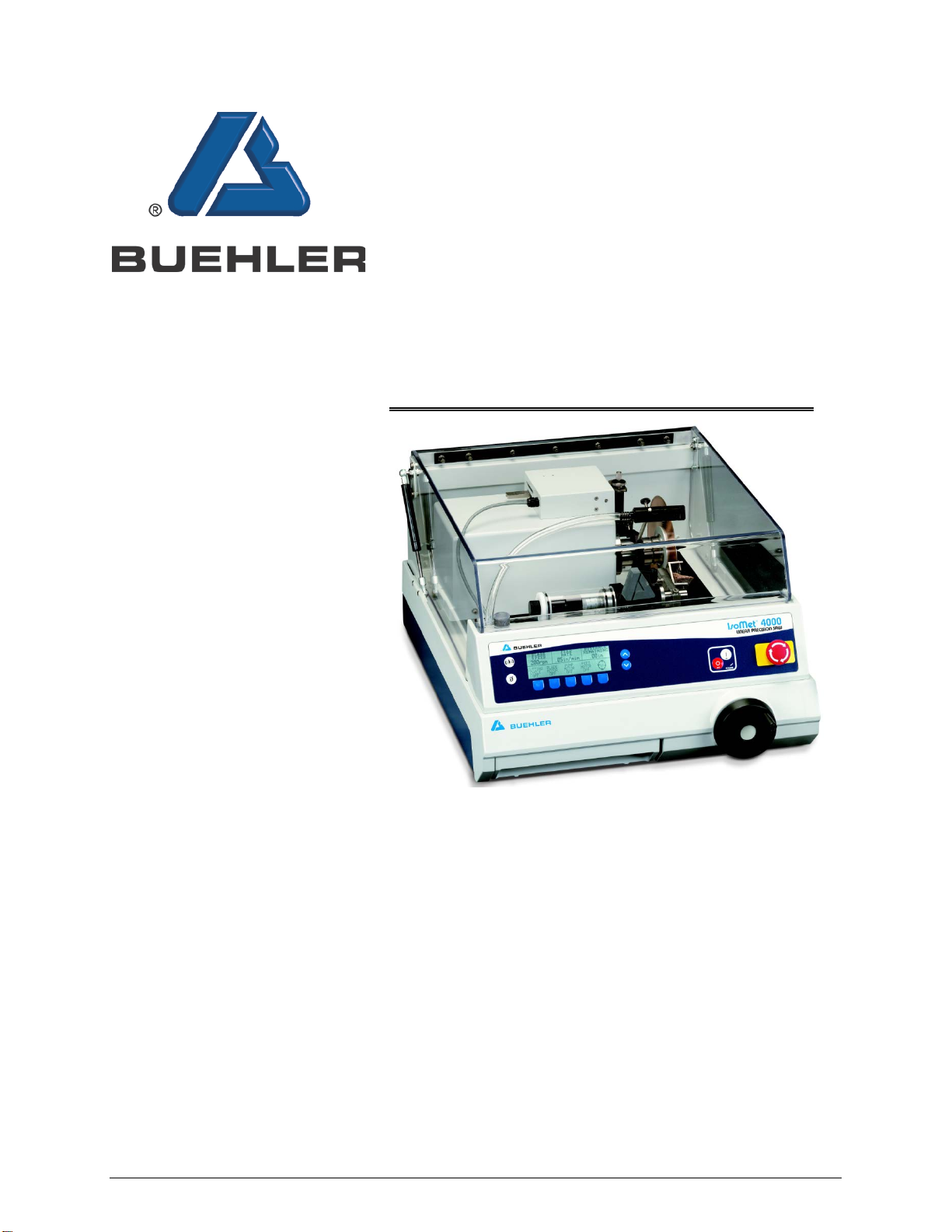
IsoMet4000 Linear Precision Saw................................................................................................................1
Warranty........................................................................................................................................................ 1
Specifications................................................................................................................................................1
Safety Information.........................................................................................................................................2
Machine Use and Care...........................................................................................................................2
Safety Terms .......................................................................................................................................... 3
Unpacking .....................................................................................................................................................3
Installation.....................................................................................................................................................4
Electrical Installation .....................................................................................................................................4
Blade Installation...........................................................................................................................................5
Installing a Blade..............................................................................................................................5
Cooling and Lubrication ................................................................................................................................6
Vises.............................................................................................................................................................. 6
External Recirculating System......................................................................................................................7
IsoMet 4000 Controls and Functions ............................................................................................................8
Front Panel Controls............................................................................................................................... 8
IsoMet 4000 Display Screens and Commands...........................................................................................10
Parameter Fields ..................................................................................................................................10
L1 Display Screen.................................................................................................................................11
L1 Display Screen Commands ......................................................................................................11
Pause CUTTING CYCLE...............................................................................................................11
L2 Display Screen.................................................................................................................................12
L2 Display Screen Commands ......................................................................................................12
L3 Display Screen.................................................................................................................................13
L3 Display Screen Commands ......................................................................................................13
Specimen Positioning..................................................................................................................................14
Specimen Loading................................................................................................................................14
Positioning a Specimen with an Unknown Thickness..........................................................................14
Positioning a Specimen with a Known Thickness................................................................................16
Operation.....................................................................................................................................................17
Cutting a Specimen ..............................................................................................................................17
Single Cut.............................................................................................................................................17
Manual Cutting......................................................................................................................................18
SMART CUT: Checking and Adjusting the Feed Rate ...............................................................................19
Blade Dressing............................................................................................................................................19
Dressing the Blade ...............................................................................................................................20
Automatic Blade Dressing, Rotating Chuck, and Specimen Positioning System.......................................21
Removing the Specimen Position System (Catalog Number 11-2699).........................................21
Installing the Specimen Position System.......................................................................................22
Removing the Rotating Chuck (Catalog Number 11-2695) ...........................................................22
Installing the Rotating Chuck.........................................................................................................22
Removing the Automatic Blade Dressing System (Catalog Number 11-2696).............................22
Installing the Automatic Blade Dressing System ...........................................................................23
Warning Messages .....................................................................................................................................24

Table of Contents
vi
MA112680_39.3 [Original Instructions] 4/2014
Maintenance................................................................................................................................................25
Internal Coolant/Lubricant Recirculating System .................................................................................25
Draining the Coolant ......................................................................................................................25
Cleaning the Unit..................................................................................................................................26
Automatic Blade Dressing ....................................................................................................................26
Cleaning the Automatic Blade Dressing shaft ...............................................................................26
Checking the Blade Motor Total Hours ................................................................................................27
Troubleshooting Chart.................................................................................................................................28
Application Guide........................................................................................................................................29
Buehler Environmental Policy.....................................................................................................................31

1
MA112680_39.3 [Original Instructions] 4/2014
IsoMet4000 Linear Precision Saw
The IsoMet 4000 is an easy to use automatic linear saw that includes the SMARTCUT system to
automatically adjust the feed rate to provide consistent, quality cuts and to prevent specimen and
machine damage.
A 1µm Specimen Positioning System allows for precise applications and enables the cutting of delicate
specimens with minimal deformation.
Three IsoMet 4000 models are available:
•11-2680 IsoMet 4000 Precision Saw with accessories.
•11-2681 IsoMet 4000 Precision Saw without accessories.
•11-2675 IsoMet 4000 Precision Saw with accessories and external recirculating system.
Warranty
This unit is guaranteed against defective materials and poor workmanship for a period of 24 months or
2000 hours of normal use (whichever comes first), from the date of receipt by the customer. The warranty
is void if inspection shows evidence of abuse, misuse, unsafe use or unauthorized repair. This warranty
covers all Buehler costs associated with the replacement of defective materials (e.g., parts and labor).
If for any reason this unit must be returned to Buehler for warranty service, please contact Buehler
Service at www.Buehler.com or 1-800-283-4537 for prior authorization and shipping instructions.
(If outside the USA or Canada contact your local Buehler Representative.) Please have the following
information available when contacting Buehler:
•Customer Purchase Order Number
•Buehler Invoice Number and Date
•Serial Number
•Reason for return
Specifications
11-2680 / 11-2681 / 11-2675 IsoMet 4000 Precision Saw
Dimensions 21 ½” W x 29 ½” D x 13 ¼” H (546 mm x 750 mm x 337 mm)
Electrical 85 – 264 V, 50/60 Hz, 1 Phase
Motor 1 ¼ hp (795 W)
200 – 5000 rpm
Decibels (No Load, 12 inches away level from machine) 73 dB
Shipping Weight 130 lbs (56 kg)
Coolant Tank .9 gal (4 liter)
Coolant Flow Rate .7 gal/min (3 liter/min)

2
MA112680_39.3 [Original Instructions] 4/2014
Safety Information
For safe installation and operation of this equipment, carefully read and understand the contents of this
manual. Improper operation, handling, or maintenance can result in severe personal injury and equipment
damage.
The IsoMet 4000 Linear Precision Saw is designed for use in dry, indoor laboratory and workshop
environments away from strong electromagnetic fields and with normal temperature ranges
(41° F to 104° F / 5° C to 40° C) and non-condensing humidity ranges (30-90%).
Machine Use and Care
All operators should be trained in the use of the IsoMet 4000. If training is needed contact
Buehler at 800.BUEHLER (800.283.4537) or your local Buehler Sales Representative.
Always use safety glasses. Flying debris and liquids can cause severe eye injury.
Dress properly. Protective equipment should be worn to handle specimens, which may be sharp
or hot.
Do not operate machine in explosive atmospheres, such as in the presence of flammable
liquids, gases, or dust. Sparks may ignite the dust or fumes. Flammable material must not be
used with the IsoMet 4000 Linear Precision Saw.
Maintain the IsoMet 4000 Linear Precision Saw with care. Properly maintained machines are
less likely to bind and are easier to control. Any alteration or modification is a misuse and may
result in a dangerous situation.
Maintain machine guards and interlocks. Do not attempt to enter the cutting bay when the
IsoMet 4000 Linear Precision Saw is in use.
Only qualified repair personnel must perform machine service. Service or maintenance
performed by unqualified personnel could result in a risk of injury.
Replace damaged or defective parts immediately and use only identical replacement parts.
Use of unauthorized parts or failure to follow maintenance instructions may create a risk of
electrical shock or injury.
Check for misalignment or binding of moving parts, breakage of parts, and any other
condition that may affect the machine operation. If damaged, have the machine serviced
before using. Poorly maintained machines cause many accidents.
Machine coolant can present a biological hazard if not maintained correctly. Change the
coolant regularly in accordance with local regulations and safety practices.
Use of extension cords is not recommended for Buehler machines and equipment.

3
MA112680_39.3 [Original Instructions] 4/2014
Safety Terms
DANGER
!
WARNING
!
CAUTION
!
NOTICE
Unpacking
The IsoMet 4000 Linear Precision Saw is shipped fully assembled and has been carefully packaged to
protect it during transit from the factory to your location. Carefully unpack and check contents.
If any components are missing or damaged, save the packing list and materials and advise the carrier
and Buehler of the discrepancy.
IsoMet 4000 Linear Precision Saw with accessories (Catalog Number 11-2680)is shipped with:
•Automatic Dressing System (11-2696)
•Buehler Recommended Cutting Fluid
•Dressing Stick (11-1190)
•IsoCut®7-inch Wafering Blade (11-4267)
•Set of 4-inch Stainless Steel Flanges (11-2689)
•Short T-Slot Table (11-2701)
•1µm Specimen Positioning System (11-2699)
•2 Abrasive Cut-off Wheels (11-4207-010 & 11-4217-010)
•3 Specimen Chucks:
11-2683 - Single Saddle Chuck
11-2684 - 1 ¼-inch Round Specimen Chuck
11-2686 - Irregular Specimen Chuck
DANGER indicates a hazardous situation which, if not
avoided, will result in death or serious injury.
WARNING indicates a hazardous situation which, if not avoided,
could result in death or serious injury
CAUTION indicates a potentially hazardous situation which,
if not avoided, may result in minor or moderate injury.
NOTICE indicates practices not related to personal injury.

4
MA112680_39.3 [Original Instructions] 4/2014
Installation
WARNING
!
Equipment Damage. The IsoMet 4000 Linear Precision Saw is heavy. Follow local safety practices
to lift the IsoMet 4000 Linear Precision Saw unit from the shipping carton. Improper lifting can
result in machine damage.
Personal Injury. Improper lifting of the IsoMet 4000 Linear Precision Saw can result in personal
injury.
The IsoMet 4000 Linear Precision Saw is bolted to a wooden base for protection during shipping. Open
areas are provided at the corners of the base for ease of lifting.
Lift the IsoMet 4000 Linear Precision Saw out of the carton and position it on a table so it overhangs the
edge. Remove all bolts securing the IsoMet 4000 Linear Precision Saw to the wood base.
Select a location for your IsoMet 4000 Linear Precision Saw that provides an adequate working space, a
power source, water connections, and a drain.
Allow 6 inches (150 mm) of space at the back of the IsoMet 4000 Linear Precision Saw for raising the
hood.
Electrical Installation
Electrical Shock Hazard. Only a qualified electrical technician should perform electrical
installation and maintenance.
Electrical Shock Hazard. Do not change the power plug in any way. Buehler machines are
equipped with a polarized plug (one blade is wider than the other) and a ground pin. Polarized
plugs reduce the risk of electrical shock. This plug will fit in a polarized outlet only one way.
•Disconnect the power supply before making any electrical adjustments. Install a lockout tag
and follow lockout tag procedures to prevent any accidental starting of the machine.
•Capacitors inside the machine may retain a charge even if the machine is disconnected from
the power supply
Installation of the IsoMet 4000 Linear Precision Saw must comply with local electrical standards or codes
of practice.
The Specification Plate is located on the back of the IsoMet 4000 Linear Precision Saw. Check that the
Specification Plate values for voltage, current, and power consumption are compatible with the intended
electrical supply before installation.
The IsoMet 4000 Linear Precision Saw can be plugged into an existing outlet rated for the voltage and
frequency listed on the Specification Plate.

5
MA112680_39.3 [Original Instructions] 4/2014
Blade Installation
Flanges support the wafering and abrasive blades. Failure to provide adequate flange support may result
in curved cuts and damaged blades. When cutting always select the maximum flange diameter in
proportion with the size of the specimen.
Installing a Blade
1. Remove the end bolt and end cap bushing from drive shaft (see Figure 1).
2. Install the outer flange on the end cap bushing.
3. Install the blade against the outer flange.
4. Slip on the inner flange on the end cap bushing.
5. Tighten the end bolt to complete the installation.
NOTICE
To prevent misalignment and damage to the blade, clean the end cap bushing, screws,
and flanges in a mild detergent solution to remove particles from prior cuttings before
installing a wafering or abrasive blade.
Figure 1 Blade Installation Diagram
Inner Flange
Outer Flange
End Bolt
End Cap
Bushing

6
MA112680_39.3 [Original Instructions] 4/2014
Cooling and Lubrication
The IsoMet 4000 has an internal pump and adjustable nozzle for lubrication and cooling. The coolant tank
is covered to prevent spills and has internal baffles. Baffles provide surface area for swarf control (debris
left over from a blade cut). The nozzle can be adjusted with the hood open and the pump on.
Only the pump will operate with the hood open. The pump can be used for coolant adjustment,
machine cleaning, and to empty the tank.
CAUTION
!
Equipment Damage. Do not allow the tank to become less than ½-inch below full. This will cause
the water pressure to surge.
Do not run the pump dry for more than 30 seconds.
•The internal tank holds three liters and can be filled by pouring cutting fluid into the saw bed. Fill the
coolant tank with cutting fluid.
Using only water is not recommended.Using only water will cause damage to the internal pump
and will not be covered under warranty. The External Recirculating System (part number 11-2710) is
recommended for procedures that require using just water.
•Do not over fill the coolant tank. The true level of the liquid is indicated on the front of the tank and
not at the drain inside the cutting chamber.
•During high frequencies of use or when using abrasive cut-off wheels with the IsoMet 4000 Linear
Precision Saw, the coolant tank should be cleaned regularly. The drain screen should be cleaned
between each cut to prevent blockage. (For high frequencies of use, it is highly recommended to use
the External Recirculating System, part number 11-2710).
•If the IsoMet has not been operation for a long period of time or the coolant has been change, prime
the pump for 10 – 20 seconds before use. Press the PUMP MOTOR button to ON (see page 10).
•If the IsoMet has not been operation for a long period of time or the protective residue on the
machinery appears gummy, run the coolant first to wet the surfaces before moving the turret/hand-
crank. This will extend the life of the rail seals and linear bearings.
Vises
The general use vise (Catalog Number 112691) is constructed of hardened and ground tool steel. This
gives the best performance and accuracy, and will hold specimens up to 2 inches (50 mm) in size.
The vise must be oiled after each use if only water is used as a cutting fluid. Using only water is not
recommended.

7
MA112680_39.3 [Original Instructions] 4/2014
External Recirculating System
WARNING
!
Personal Injury. Disconnect the power supply before performing any maintenance or adjustments.
1. Determine a location for the External Recirculating System.
2. Set the tank on a four-wheeled recirculating cart (P/N 16-1497).
3. Slide the 1-inch drain hose over the drain outlet pipe and secure the drain hose with the supplied
hose clamp (see Figure 2)
4. Connect the water supply hose to the supply fitting on the recirculating tank
(see Figure 3).
Figure 2 1-inch drain outlet pipe Figure 3 Supply fitting on the recirculating tank
5. Connect the power cord from the saw to the 12-volt power plugs from the saw to the banana plugs on
the recirculating tank (see Figure 3).
a. Plug the BLACK banana plug into the BLACK connector.
b. Plug the RED banana plug into the RED connector.
6. Fill the recirculating tank with seven (7) gallons of mixed
coolant or until the mixed coolant reaches the top of the
first or third baffle (see Figure 4).
7. Insert the drain hose into the large hole on the
recirculating tank. The drain hose can be cut to length to
facilitated easier installation.
8. The front control panel command buttons operate the
External Recirculating Tank.
Fill to this level.
Figure 4
External Recirculating Tank Baffles

8
MA112680_39.3 [Original Instructions] 4/2014
IsoMet 4000 Controls and Functions
Before operating the IsoMet4000 lightly oil all exposed metal parts. During operation the coolant will
maintain a protective film of oil on all exposed metal.
When the IsoMet 4000 is not in use raise the hood. This will minimize possible corrosion.
A glass-reinforced, splash-proof plastic hood encloses the entire cutting area to prevent loss of coolant
and decrease noise. When raised, the counter-balanced hood will remain in the open position, activating
a safety-lock switch disabling the controls for the cutting motor.
1. Activate power to the IsoMet4000. Flip the power switch on the back of the machine to the ON
position.
2. On the front control panel press the ON button.
•The front panel LCD will light up and scroll through the display screen.
•Raise the hood to allow access to the cutting bay.
Front Panel Controls
POWER
OFF
ON
R
IsoMet 4000
LINEAR PRECISION SAW
1
2
3
4 5
6
EMERGENCY
STOP
The front panel consists of six (6) dedicated buttons, five (5) software/multi-function softkey
buttons, an Emergency Stop button, and a large Liquid Crystal Display (LCD) with back lighting.
All buttons have tactile feedback.
ON
Power ON The Power ON button will activate the IsoMet system.
When first turned ON, the LCD screen will scroll through the Buehler name, logo,
type of machine, and latest firmware revision.
After 10 seconds the screen will change to display the BLADE SPEED, FEED RATE,
and DISTANCE REMAINING parameter information as well as the softkey button
commands for the L1 screen.
OFF
Power OFF The Power OFF button will deactivate the IsoMet system. The Power
OFF button will store all previous set parameters before powering off.

9
MA112680_39.3 [Original Instructions] 4/2014
Scroll The SCROLL button scrolls through the different parameter fields highlighting
each one as it is selected. The parameter fields will change depending on how many
times the SCROLL button is pressed.
There is a total of four (4) parameters that can be displayed: BLADE SPEED, FEED
RATE, DISTANCE REMAINING, CUTTING DISTANCE.
Zero The ZERO button is used to indicate the SOFT HOME position by positioning
the blade and the Micrometer Positioning System (if attached) at a starting point just
before the specimen.
Once a position is determined, press the ZERO button and the DISTANCE
REMAINING value will change to .00, indicating the SOFT HOME position.
Increase The Increase button will incrementally increase (raise) a parameter’s
value. The maximum values for the IsoMet 4000 are:
•BLADE SPEED = 5000 rpm
•FEED RATE = .75 in/min [19 mm]
•CUTTING DISTANCE = 8.00 inches [203 mm]
Decrease The Decrease button will incrementally decrease (lower) a parameter’s
value. The minimum values for the IsoMet 4000 are:
•BLADE SPEED = 200 rpm
•FEED RATE = .05 in/min [1.27 mm]
•CUTTING DISTANCE = .01 inch [.26 mm]
EMERGENCY STOP
Is the big red knob on the right side of the front panel. When pressed all electrical
power is disconnected from the blade and all moving parts, disabling any further
operations.
A warning message will appear when the Emergency Stop button is pushed.
To return power, turn the Emergency Stop knob clockwise.
Press the CUTTING CYCLE button to continue operation.

10
MA112680_39.3 [Original Instructions] 4/2014
IsoMet 4000 Display Screens and Commands
Parameter Fields
There are four (4) different parameter fields available. Use the SCROLL button to scroll though
the LCD Screens to display and highlight the parameters.
BLADE
SPEED
4250rpm
FEED
RATE
.64in/min
DISTANCE
REMAINING
1.00in
CUTTING
CYCLE
ON
BLADE
MOTOR
ON
PUMP
MOTOR
ON
FEED
MOTOR
ON
L1
BLADE SPEED, FEED RATE, and DISTANCE REMAINING parameter fields.
BLADE
SPEED FEED
RATE CUTTING
LENGTH
Press the SCROLL button to display the CUTTING LENGTH parameter.
Softkey Buttons
activate or deactivate a
function.
Parameter fields are
highlighted using the
Scroll button.
Functions
are controlled (ON or OFF)
by softkey buttons.

11
MA112680_39.3 [Original Instructions] 4/2014
L1 Display Screen
BLADE
SPEED
4250rpm
FEED
RATE
.64in/min
DISTANCE
REMAINING
1.00in
CUTTING
CYCLE
ON
BLADE
MOTOR
ON
PUMP
MOTOR
ON
FEED
MOTOR
ON L1
L1 Display Screen Commands
Button [1] CUTTING CYCLE starts, stops, and pauses the cutting cycle.
Button [2] BLADE MOTOR activates [ON] or deactivates [OFF] the blade motor. The blade
will rotate at a set speed and the hood must be closed.
Button [3] PUMP MOTOR activates [ON] or deactivates [OFF] the coolant pump motor.This
is the only function that will work while the hood is open.
Button [4] FEED MOTOR activates [ON] or deactivates [OFF] the feed motor. The FEED
MOTOR can be used to position the blade and will only operate when the blade
is rotating.
Button [5] Scrolls the LCD Screen between Screen L1, Screen L2, and Screen L3.
Pause CUTTING CYCLE
To pause the cutting cycle, press the CUTTING CYCLE button once.
When the CUTTING CYCLE is in the STOP and PAUSE mode, the L4 screen will become
available.
BLADE
SPEED
4250rpm
DISTANCE
REMAINING
1.00in
CUTTING
CYCLE
ON
BLADE
MOTOR
ON
PUMP
MOTOR
ON
FEED
MOTOR
ON L1
FEED
RATE
.64in/min

12
MA112680_39.3 [Original Instructions] 4/2014
L2 Display Screen
BLADE
SPEED
4250rpm
FEED
RATE
.64in/min
DISTANCE
REMAINING
1.00in
CUTTING
CYCLE
ON
ROTATING
CHUCK
ON
SOFT
START
OFF
SOFT
START
OFF L2
L2 Display Screen Commands
Button [1] CUTTING CYCLE starts, stops, and pauses the cutting cycle.
Button [2] ROTATING CHUCK activates [ON] or deactivates [OFF]. The chuck will rotate at
a constant speed.
Button [3] SOFT START selects the Soft Start option. This will slow the selected FEED
RATE for the first .06-inch [1.52 mm] of a cut.
Button [4] SOFT STOP selects the Soft Stop option. This will slow the selected FEED
RATE for the last .25-inch [6.35 mm] of a cut.
Button [5] Scrolls the LCD Screen between Screen L2, Screen L3, and Screen L1.

13
MA112680_39.3 [Original Instructions] 4/2014
L3 Display Screen
BLADE
SPEED
4250rpm
FEED
RATE
.64in/min
DISTANCE
REMAINING
1.00in
CUTTING
CYCLE
ON
DRESS
BLADE
OFF
IMPERIAL
UNITS
SELECT
ENGLISH
LANGUAGE L3
L3 Display Screen Commands
Button [1] CUTTING CYCLE starts, stops, and pauses the cutting cycle.
Button [2] DRESS BLADE sets the correct blade-dressing parameters and activates the
automatic dressing mechanism (if attached).
Button [3] UNITS changes between METRIC and IMPERIAL (English) units of measure.
Button [4] LANGUAGE allows the operator to select a language from the list. The
languages currently available are:
•English
•French
•German
•Spanish
•Portuguese
•Japanese
•Chinese
•Korean
Button [5] Scrolls the LCD Screen between Screen L3, Screen L1, and Screen L2.

14
MA112680_39.3 [Original Instructions] 4/2014
Specimen Positioning
Specimen Loading
Several chucks are available to hold specimen of many different sizes and shapes. Select the
proper chuck for the particular application and attach it to the T-slot bed.
CAUTION
!
Equipment Damage. Secure the specimen into the chuck and the chuck to the vise bed to
prevent slipping or rotation during cutting. Improper clamping or chuck selection may
cause blade damage.
Positioning a Specimen with an Unknown Thickness
1. Turn the hand crank clockwise until the blade is beyond the chuck position.
2. Determine the cut length of the specimen.
a. Position the specimen in the chuck so the cutting blade can pass by the chuck without
touching the specimen (see Figure 5).
b. Turn the hand crank counter-clockwise to bring the blade forward until it is just behind the
and almost touching the specimen (see Figure 6).
c. Press the ZERO button on the control panel and the DISTANCE REMAINING field
value will display .00 in (or .00 mm).
BLADE
SPEED
600 rpm
FEED
RATE
.75 in/min
DISTANCE
REMAINING
.00 in
d. Turn the hand crank counter-clockwise until the blade travels the width of the cut (see
Figure 8).
e. Look at the REMAINING DISTANCE field on the LCD screen. The value displayed is how
long the cut will be (without the minus sign).
BLADE
SPEED
600 rpm
FEED
RATE
.75 in/min
DISTANCE
REMAINING
-.60 in
This manual suits for next models
3
Table of contents
Other Buehler Laboratory Equipment manuals
Popular Laboratory Equipment manuals by other brands

NoiseKen
NoiseKen LSS-6330-B63A instruction manual

BURREL
BURREL 077-870-0300 operating manual

Life technologies
Life technologies EVOS XL Core quick reference

Heidolph
Heidolph Hei-MIX Titramax 100 operating manual

Knauer
Knauer Azura Assistant ASM 2.1L user manual

B&W Tek
B&W Tek i-Raman Plus quick start guide