Buffalo DC331-N Owner's manual

Gas Char Grill
Installation and Operation Instructions
Model: DC331-N, DC331-P, CF380-N, CF380-P
IMPORTANT FOR FUTURE REFERENCE
Please complete this information and retain this manual for the life of the equipment. For
Warranty Service and/or parts, this information is required.
Model Number Serial Number Date Purchased
WARNING: For your safety, do not store or use gasoline or other flammable vapors or
liquids in the vicinity of this or any other appliances. Keep the area free and clear of
combustible materials.
WARNING:Improper installation, adjustment, alteration, service or maintenance can
cause property damage, injury, or death. Read the installation operating and
maintenance instructions thoroughly before installing, or servicing this equipment.
WARNING:Instructions must be posted in a prominent location. All safety precautions
must be taken in the event the user smells gas. Safety information can be obtained from
your local gas supplier.
WARNING:Components must not be cleaned in a dishwasher
Nisbets PLC
Fourth Way, Avonmouth, Bristol, BS11 8TB,
Unit 9003, Blarney Business Park, Blarney,Co. Cork

2
Table of Contents
I..... Introduction................................................................................3
II. .. Specifications..............................................................................4
III.. Installation Guide ........................................................................6
IV. . Operation Guide ........................................................................ 13
V. ... Cleaning Instructions ................................................................. 17
VI.. Gas Conversion ......................................................................... 19
VII. Troubleshooting Guide................................................................ 23
VIII.Exploded View .......................................................................... 30
IX.. Spare Parts List ......................................................................... 32

3
I. Introduction
CE Only:
These instructions are only valid if the country code appears on the appliance. If the code does not
appear on the appliance, refer to the supplier of this appliance to obtain the technical instructions for
adapting the appliance to the conditions for use in that country.
VERY IMPORTANT! READ THIS FIRST
Before installing and operating this equipment, ensure that everyone involved in its operation are fully
trained and are aware of all precautions. Accidents and problems can result from a failure to follow
fundamental procedures and correct operation.
A colour version of this manual is available online
IMPORTANT REMINDER!
Care must be taken by the operator to use the equipment safely, and to guard it against risk
of fire. The following precautions must be adhered to:
a. The equipment must not be left unattended, while it is in operation.
b. It is recommended that a regular inspection is carried out by a competent service person
to ensure correct and safe operation of your equipment is maintained.
c. Do not spray aerosols in the vicinity of this appliance while it is in operation.
d. The equipment must not be operated without the feet/gas stand fitted.
CAUTION!
To avoid property damage, personal injury or death, all gas joints and connections disturbed
during servicing, repair, gas conversion, and installation, must be checked for gas leaks. Use
only gas leak detecting solutions or soap and water solution (bubble test) to check for gas
leaks. Do not use naked flame to check for gas leaks.
CAUTION!
This commercial cooking equipment is for professional use and shall be used by qualified
persons.

4
II. Specifications
A. General
1. A commercial heavy-duty gas Char-Grill.
2. It uses lava rocks or cast radiants.
B. Pack Contents
1. Buffalo Gas Char-Grill
2. Cast Radiant (Standard), Lava Rocks (Optional)
3. Gas Stand
4. Instruction Manual
C. Dimensions
Models
Length (mm)
Height (mm)
Depth
(mm)
DC331-P
610
372
730
DC331-N
610
372
730
CF380-P
610
372
730
CF380-N
610
372
730

5
D. Gas Specification Table
Gas Type
Natural Gas
(G20)
Propane
(G31)
Butane
(G30)
Models
DC331-N
CF380-N
DC331-P
CF380-P
DC331-P
CF380-P
Single burner Heat
Input (KW)
7.15
7.15
7.15
No. of burners
2
2
2
Total Heat Input (KW)
14.3
14.3
14.3
Manifold Pressure
(mbar)
20
37
30
Supply Pressure
(mbar)
20
37
30
Gas Connection
¾” BSP
¾” BSP
¾” BSP
Main burner injector
Injector Mark
(Orifice Size in mm)
#47
(Ø1.99)
#54
(Ø1.4)
#54
(Ø1.4)
Pilot injector
Injector Mark
(Orifice Size in mm)
#45
(Ø0.45)
#25
(Ø0.25)
#25
(Ø0.25)
U-Burner
Air Shutter
Set-up
Default
Setting
Fully open
Fully open
Fully open
Adjustment
Adjust only if
necessary.
Adjust only if
necessary.
Adjust only if
necessary.
Burner Low
Flame
Bypass
Screw
Screw
Hole Size
Ø1.6mm
(Ex-Factory)
Ø 0.7mm
(Ex-Factory)
Ø 0.7mm
(Ex-Factory)
Default
Setting
Fully Closed
From fully closed position, turn or
open by 90°counter-clockwise.
Lock Screw
Air Shutter
Low flame bypass screw

6
III. Installation Guide
A. Installation Requirements
1. Only qualified and/or authorized persons must carry out the installation, gas conversion, and
servicing/repair of this equipment.
2. Components having adjustments protected by the manufacturer are not to be adjusted by the
installation person. They must only be adjusted by an authorized Service Engineer.
3. This equipment must be installed in an area with sufficient ventilation to prevent the occurrence
of unacceptable concentrations of substances harmful to health.
4. The installation of this equipment must comply with the local gas, health, and safety
requirements.
5. The warranty will be void if this equipment was not installed in accordance with the
manufacturer’s specification and relevant National and Local codes.
6. This equipment must be installed in accordance with relevant National Installation codes, and in
addition, in accordance with relevant National and Local codes covering gas and fire safety.
Australia:
AS 5601/AG 601 (to be AS 5601)- Gas Installations
New Zealand:
NZS 5261 - Gas Installation.
United Kingdom:
Gas Safety (Installation and Use) Regulations 1998
BS 6173-Installation of Catering Appliances.
BS 5440-1&2 Installation Flueing & Ventilation.
Ireland:
IS 820-Non Domestic Gas Installations.
B. Unpack the equipment
1. Remove all packaging and transit protection from the appliance including all protective film
coating from the exterior stainless steel panels. NOTE: Take caution when unpacking the
equipment, as wood pallets or skids can contain splinters and nails. Shipping cartons can contain
large staples. Ensure to wear cut-resistant gloves and protective eyewear during unpacking,
opening, removing and disposing of shipping containers.
2. Upon opening the package, check immediately the equipment and accessories/parts for any
damage or deficiency.
3. Upon checking of the unit, report immediately to the carrier and the distributor, for any damage
or deficiency on the equipment, and its accessories or parts.
C. Establish the operational location of the equipment
1. This equipment must be installed in an area with sufficient ventilation to prevent the occurrence
of unacceptable concentrations of substances harmful to health.
2. Install the equipment in an area which provides enough airflow for combustion.
3. All air for burner combustion is supplied from underneath the unit. The feet/stands must always
be fitted and no obstruction must be placed on the underside or around the base of the unit, as
obstruction will cause incorrect operation and/or failure of the appliance.
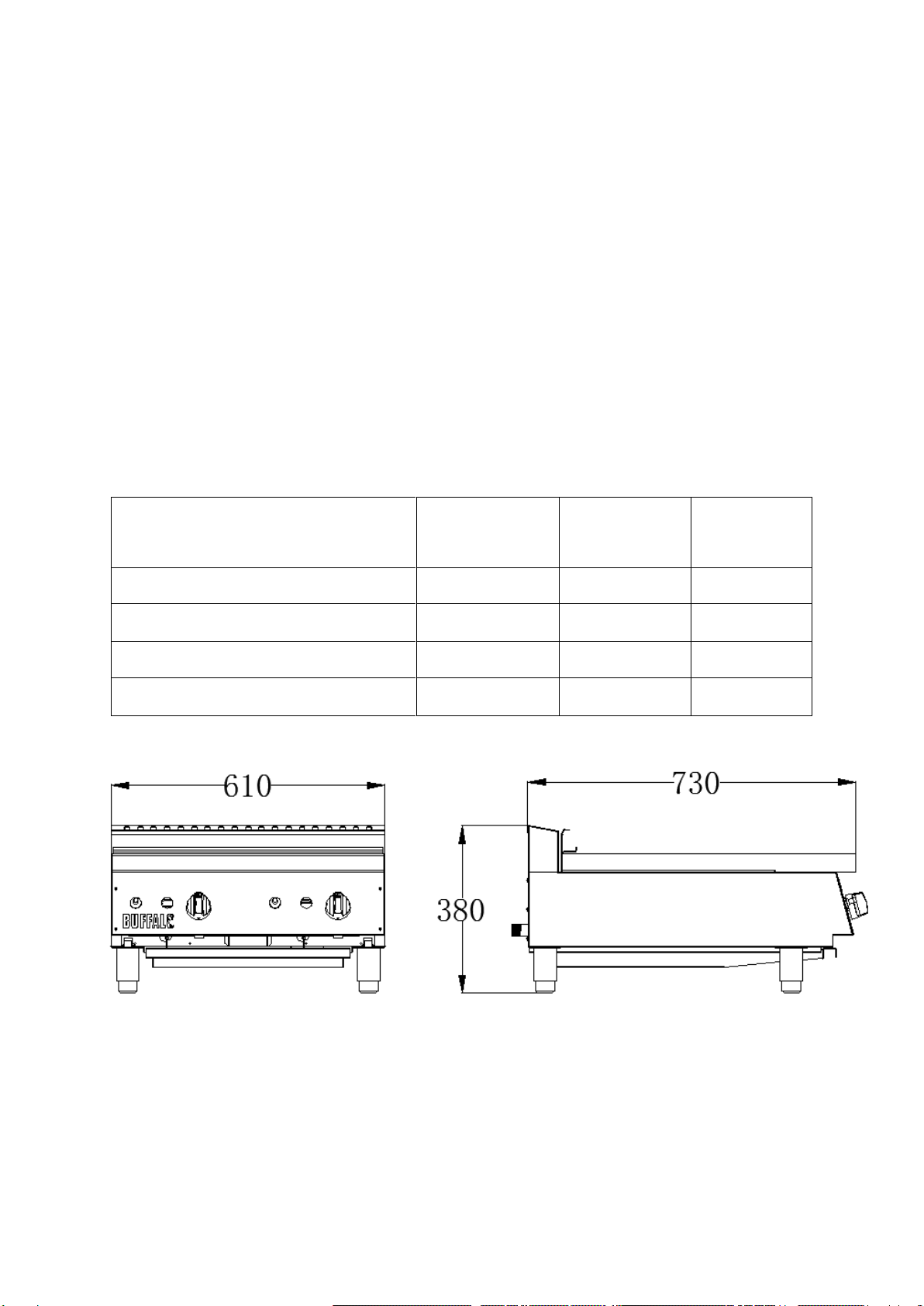
4. Position the appliance in its approximate working location, then install the feet or gas stand
provided.

7
5. Do not put the equipment in an area where the equipment’s flue may be obstructed. Also, do
not directly connect the equipment’s flue to any ventilation equipment or system.
6. Any gas burning appliance requires adequate clearance and ventilation for optimum and trouble-
free operation. The minimum installation clearances shown are to be adhered to.
Clearances
NOTE: THESE UNITS ARE SUITABLE FOR INSTALLATION ON NON-COMBUSTIBLE
SURFACES ONLY.
For use in non-combustible locations only
For use only on non-combustible countertops
Noncombustible and unit clearances: sides and rear – 10”(250mm) floor
NOTE: This Gas Char-Grill is supplied with adjustable stand/feet to enable the appliance to be
positioned securely and level. The installation of the gas stand should be carried out
before the completion of the gas connection.
D. Install the gas stand
1. Remove the feet from the packaging
2. For initial installation, remove radiant and cast grate, upturn and support your gas equipment,
taking care as items may be heavy. Screw the feet into the gas equipment.
3. Locate the equipment into its final operating position. Then, using a sprit level, adjust the feet
to the correct level and height. Then, install the flue and all the cast radiants and cast grates.
feet

8
E. Install the Flue
1. Remove the Flue from the packaging, then remove all protective film from the flue.
2. Install the flue at the back of the unit by pushing it down.
F. Install the cast radiants (for units with cast radiants)
1. Remove the cast radiants from the packaging.
2. Install the cast radiants. Place each cast radiant over the “U” shaped burner tubes (peak-side
up). See image below. Ensure that the corner edges are inserted on the position slots on the
front and back radiant support flange.
Flue

9
G. Install the Lava Rock Kit (for units with Lava Rock Kit)
1. Remove the lava rocks and support racks from the packaging.
2. Then, position the support racks over the burner tubes. The support racks should rest firmly on
the front and back support flange. See image below.
3. Place the lava rocks over the support rack as shown in the photo below. Keep the excess lava
rocks for future use.
Support Rack
Lava Rocks

10
H. Install the top cast grates/grills
1. Remove the top cast grates from the packaging.
2. Install the top cast grates.
a. Horizontal installation: Place each cooking grate on the front support flange horizontally
while the rear part sits into the back support flange horizontally. See image below.
b. Inclined or slanted installation: Place each cooking grate over the front support flange
while the bottom groove of the rear part sits on TOP of the back support flange. See image
below.
Cast Grates
(Horizontal)
Grease trough
U-Burner
Cast Grates
(Slanted)
Grease trough
U-Burner

11
I. Gas Connection
1. Only qualified and/or authorized persons must carry out the gas connection, testing and
commissioning of this equipment.
2. After installing all the necessary parts, position the equipment in its final operating position.
3. Before connecting the gas supply line to the equipment, check the following:
a. Check gas type that will be supplied to the equipment. It should match the gas type
indicated on the rating label.
b. Check the gas supply pressure. It should match the equipment’s required gas supply
pressure indicated on its rating label. Ensure that adequate supply pressure exists. Adjust
the gas supply pressure if necessary.
4. Adjust the gas supply pressure according to the gas type used, and according to the gas supply
pressure indicated on the rating label. Refer also to the Gas Specification Table on page 5 of
this manual.
5. When a supply regulator is to be installed, ensure that the supply regulator is converted to the
correct gas type that the equipment will operate on. Ensure that adequate supply pressure and
manifold pressure exists.
6. It is highly recommended that an isolation valve be installed between the equipment and the
main gas supply line.
7. Connect the main gas supply to the equipment. Unless compression fittings are used, it is
essential that a suitable joining compound which resists the breakdown action of LPG or Natural
Gas, must be used on every gas line connection.
8. After connecting the main gas supply to the equipment, check all gas connections for leakages.
Use soapy water (bubble check), or any gas leak detecting solution. Do not use naked flame to
check for gas leaks.
J. Testing & Commissioning
1. Check the burner operating pressure. It is taken at the Manifold Pressure Test Point, with one
2. Remove the knobs/dials, and open the front panel cover. Take caution when opening the front
panel as the Piezo igniter wire is still plugged in, and might be damaged.
Manifold Pressure
Test Point

12
3. Remove the plug from the Manifold Pressure Test Point and install a portable manometer. Check
for gas leak on the connection.
4. Turn ON the isolation gas valve, and open one burner and set at “High Flame” for Check the
pressure reading in the manometer. The manometer pressure reading should be according to
the pressure of the gas type indicated in the rating label and on the Gas Specification Table on
page 5 of this manual.
5. Once the burner operating pressure had been confirmed to be within the requirement, turn OFF
the burner and pilot, shut off the isolation gas valve, and remove the portable manometer from
the Manifold Pressure Test Point, and return the plug. Then, check for gas leak after returning
the plug.
6. Plug in the Piezo igniter, and return the front panel cover, and the control knobs.
7. Do not leave the premises until the functions of the following were fully checked and functional:
a. Lighting of the Pilot burners
b. Lighting of the Main burners
c. Setting of the “Low Flame”
d. Turning OFF of the Main burners
e. Turning OFF of the Pilot burners
Note that the procedure of the above processes is specified in the “Operation” section of this
manual.
8. The owner of the equipment must keep this manual along with the records of the purchase and
installation of the equipment for future reference.
9. It is essential that the operator/user was instructed for the correct procedure for lighting,
operation and shutdown of the equipment.

13
IV. Operation Guide
A. Equipment Controls
OFF Position
Flame Viewing Hole
Piezo Igniter
Gas Control Knob
OFF Position
This equipment is only for professional use and that it shall be used by qualified persons.
Parts or components that have adjustments which are protected by the manufacturer or his
agents shall not be adjusted by the user/ operator.
Pilot
High Flame
Low Flame

14
B. Lighting the Pilot Burners
The burners of this Gas Char-Grill are fitted with individual standing pilots which allows the main
burners to be turned ON or OFF without the need to manually re-light the burner each time that
it is turned OFF, as the burner will automatically light itself by the pilot burner.
Flame Failure Protection is incorporated for each burner by way of a thermo-electric system
which will shut off the gas supply to that burner in the event that the pilot burner flame goes
out, so that un-burnt gas is not expelled to the surrounding area.
1. Select the pilot to be lighted.
2. Depress the gas control knob and turn it counter-clockwise to “PILOT”.
3. While the knob is depressed, light the pilot burner or use the piezo igniter provided. Once the
pilot has been lit, hold the knob depressed for 10-20 seconds after lighting the pilot burner. This
is to give ample time for the gas to flow to the pilot and heat up the thermocouple.
4. Release the knob after 10-20 seconds. The pilot burner should stay alight, if not, repeat Steps
(1 to 3 above).
5. If pilot burner was extinguished during normal operation, wait for 5 minutes before lighting it
up.
C. Lighting the Main Burners
1. Select the burner to be lighted.
2. Full flame can now be achieved by depressing the knob a little and turning it counter-clockwise
to the first stop, “HIGH” flame position.
3. To achieve simmer control, depress the knob a little and turn it counter-clockwise to the second
stop “LOW” flame. Note that the gas control knob can be rotated between “HIGH” and “LOW”
flame to achieve your required temperature.
D. Turning “OFF” the Main Burners
1. Select the burner to be turned “OFF”.
2. To turn off the main burner, but keep the pilot burner lighted, rotate the gas control knob
clockwise to “PILOT” position. Notice that the main burner will extinguish and the pilot will
remain lit.
3. It is recommended to turn “OFF” the main burners during idle periods, but let the pilot stay lit.
E. Turning “OFF” the Pilot Burners
1. Select the Pilot Burner to be turned “OFF”.
2. To turn OFF the pilot burner, rotate the gas control knob clockwise to “ l” position. Notice that
the pilot burner will extinguish.
CAUTION!
The surface temperature of the Char-Grill can reach over 300°C when the equipment is
operated at full setting.

15
F. Main burner air supply:
1. For efficient burner operation, a proper balance of gas volume and primary air supply must be
maintained which will result in complete combustion. Insufficient air supply results in a yellow
streaming flame. The primary air supply is controlled by an air shutter on the front of the burner.
2. Loosen the lock screw on the front of the burner and adjust the air shutter to just eliminate the
yellow tips of the burner flame. Lock the air shutter in place by tightening the screw.
G. Burner’s low flame adjustment
1. Turn ON the main burner and set the knob to low flame.
2. Pull out the knob from the safety gas valve.
3. Turn the low flame bypass screw clockwise to decrease the flame or turn counter-clockwise to
increase the flame. Refit the knobs after adjustment.
Air Shutter
Lock Screw
Low flame bypass screw

16
H. Start-up operation or operation from cold start
1. Turn the burners on about 5 minutes before cooking for preheating.
2. Set the knobs to the desired temperature setting or temperature. Each valve will control the gas
flow to the burner to bring that area of the unit up to the set temperature.
3. If different temperature settings are to be used, adjoining areas should be set at progressively
higher temperatures using the lowest temperatures on the outside burners. A uniform and
systematic approach to the loading of the unit will produce the most consistent product results.
I. Radiants
1. Place the radiants in their position. Make sure that the radiants are sitting properly into the slots
on the front and rear supports.
2. Radiants should be centered over straight section of the burners. Refer to page 8 of this manual
for the correct installation of the radiants.
J. Cooking grates
1. Place the top cooking grates horizontally or with the grid bars sloping toward the front. Refer to
page 10 of this manual for the correct installation of the cast grates.
NOTE: When cooking grates are placed sloping toward the front, the grooves on top will guide
the excess fat drippings into the grease trough.
K. Important reminders
1. Components protected by the manufacturer or his agent shall not be adjusted by the
user/operator.
2. The space between the legs at the bottom admits combustion air. DO NOT BLOCK THIS SPACE.
3. All burners are lit from constantly burning pilots. Turning the valve to the desired temperature
setting is all that is required to put the unit in service.
4. Do not permit fans to blow directly at the unit. Wherever possible, avoid open windows next to
the units' sides or back. Avoid wall type fans which create air cross-currents within a room.
5. It is also necessary that sufficient air should be allowed to enter the room to compensate for the
amount of air removed by any ventilating system. Otherwise, a subnormal atmospheric pressure
will occur, affecting operation and causing undesirable working conditions.
6. A properly designed and installed hood will act as the heart of the ventilating system for the
room or area in which the unit is installed, and will leave the unit independent of changing draft
conditions.
7. All valves must be checked at least annually. This must be done by an authorized service
representative in your area.
8. Please wait at least 15 seconds to restart the main burners to maintain the best function of the
safety gas valve after turning off the main burners.
VERY IMPORTANT!
You must contact your authorized service personnel so that the appliance is serviced
immediately when abnormal conditions, such as, partial or full loss of burner flame, abnormal
burner flame, and other burner control problems arise. When such abnormal conditions were
noticed, you must not to use or operate the equipment until it has been serviced and
commissioned properly by any authorized service personnel.

17
V. Cleaning Instructions
A. INITIAL CLEANING:
Prior to operating your new Char-Grill, perform the Cast Grates “Burn-OFF”, when the Char-
Grill is first heated, it will smoke until oil used in manufacturing, preservation and dust from
storage and shipping are burned off. Wash with soap and water before use.
B. DAILY CLEANING:
1. Remove the grease pan and empty it.
2. Cast Grates “Burn-OFF”. The grease buildup on the grates should be cleaned daily (or more often
as needed). Do not cover the top of the grates during “Burn-OFF” operation. Restricting the air
flow by covering the grates may cause them to warp. It will also cause damage to the valves,
knobs, and front panel.
Caution: When handling grates or radiants, always use heat insulated gloves to prevent burns.
Warning: Do not cover the top of the grates during a burn off operation. Restricting the airflow
by covering the grates may cause them to warp. It will also cause damage to the valves, the
knobs and the front panel.
3. Place grates on Char-Grill, with grid bars horizontal, facing down.
4. Wash the Char-Grill with soap and water after it runs cold
5. Turn off the Char-Grill and allow it to cool for 20 Minutes or more.
6. Clean top and bottom surfaces of the grates with a soft wire brush to remove fats and
caramelized grease.
7. Clean channels on grates with a scraper.
8. Remove radiants from Char-Grill. Clean the top surface of radiants with soft wire brush to remove
any food debris or caramelized grease deposits.
9. For units with lava rocks, remove the lava rocks and wash them with mild detergent and with
warm water.
10. Brush the rocks with soft bristled brush to remove any food debris or caramelized grease that
stuck on the rocks. Check the rocks for cracks and damage, and replace with new ones if
necessary.
11. Then return the cast grates properly to the equipment. See also page 11 for correct installation
of cast grates.
NOTE:
a. If the Char-Grill usage is very high, we recommend that a more thorough cleaning is carried
out on a more frequent basis. Refer to WEEKLY CLEANING.
b. DO NOT use harsh abrasive detergents, strong solvents or caustic detergents as they will
damage the grate and burners.
CAUTION!
Always turn the unit OFF, and follow the lock-out/tag-out procedure before performing
cleaning and maintenance operation.
Allow the unit to cool down first, before starting any cleaning and maintenance operation.

18
C. WEEKLY CLEANING:
1. Remove the grease pan, empty and wash it with mild detergent and warm water, applied by
sponge or soft cloth. Then, dry it with a soft dry cloth.
2. To remove normal dirt, clean the flue and exterior body of the equipment with mild detergent
and warm water, applied by sponge or soft cloth. Do not use wire brush or steel scouring pads
to remove grease and food splatter from the flue and external body of the equipment.
3. To remove grease and food splatter, which have BAKED on the equipment, apply cleanser to a
damp cloth or sponge and rub cleanser on the metal in the direction of the polishing lines, so
that it will not mar the finish of the stainless steel. Never rub with a circular motion.
4. Grate "burn off'. The grease buildup on the grates should be cleaned daily (or more often as
needed).
Caution: When handling grates or radiants, allow to cool and always use heat insulated gloves
to prevent burns.
Warning: Do not cover the top of the grates during a burn off operation. Restricting the airflow
by covering the grates may cause them to warp. It will also cause damage to the valves, the
knobs and the front panel.
5. Place grates on Char-Grill, with grid bars horizontal, facing down.
6. Turn the Char-Grill on for approximately 45 minutes.
7. Turn off the Char-Grill and allow it to cool for 20 Minutes or more.
8. Clean top and bottom surfaces of the grates with mild detergent and warm water using a soft
wire brush to remove fats and caramelized grease.
9. Clean channels on grates with a scraper.
10. Rinse the cast grates with warm water and dry thoroughly with a dry cloth
11. Remove radiants from Char-Grill. Clean the top surface of radiants with a mild detergent and
warm water, and with soft wire brush to remove any food debris or caramelized grease deposits.
12. For units with lava rocks, remove the lava rocks and brush the rocks with soft bristled brush to
remove any food debris or caramelized grease that was stuck on the rocks.
13. Check the rocks for cracks and damage, and replace with new ones if necessary.

19
VI. Gas Conversion
1. Replace the Main Burners Injectors
a. Remove the gas control knobs from the front control panel. The control knobs are a push
fit onto the shaft of the gas control valves.
b. Remove the front control panel by slackening the 4 screws on the front of the control panel
and remove the panel from the front of the appliance. Take caution when opening the front
panel and ensure to disconnect the electrical connection lead wire from the rear of the piezo
igniter fitted at the control panel.
c. Remove the cast grates and radiants.
d. Remove the cotter pin which locks the burner in place, and then remove the U-burner.
e. Remove the Main Burner Injector using a 13mm spanner.
f. Determine the correct Orifice size for the new gas type. Refer to the Gas Specification
Table on page 5 of this manual.
g. Replace with the correct Main Burner Injector Orifice size (refer to the Gas Specification on
page 5).
h. Return the U-Burner, and return the cotter pin to lock the U-Burner in place. Ensure that
the U-burner and main burner injector are properly aligned with each other.
CAUTION!
Only qualified/authorized service persons are to carry out gas conversion operations.
Before proceeding with the gas conversion procedure, allow the unit to cool down first, and
ensure that the main gas supply connected to the equipment is shut-off, and lock-out/tag-
out procedure is followed, to prevent injury to persons or damage to properly.
Igniter wire
Main Burner Injector

20
2. Replace the Pilot Injectors
a. Remove the pilot cover. Slacken the two screws of the pilot cover and remove it.
b. Disconnect the pilot pipe assembly from the pilot injector. Slacken the nut of the pilot pipe
to allow for easy removal. Use 10mm spanner
c. Remove the pilot injector from the pilot assembly.
d. Determine the correct pilot injector orifice size, refer to the Gas Specification Table on page
5 of this manual. Install the pilot injector to the pilot assembly.
e. Re-connect the pilot pipe assembly to the pilot injector.
3. Low flame bypass screw Conversion
a. Determine the correct Orifice size for the new gas type. Refer to the Gas Specification
Table on page 5 of this manual.
4. Remove the plug from the Manifold Pressure Test Point and install a manometer. Check for gas
leak on the connection.
Pilot pipe
assembly
Pilot Injector/
FDS Injector
Manifold Pressure
Test Point
Pilot Cover
Allen screws
This manual suits for next models
3
Table of contents
Other Buffalo Grill manuals

Buffalo
Buffalo Bistro DY993 User manual

Buffalo
Buffalo GF453 User manual

Buffalo
Buffalo Kamado BBQ User manual

Buffalo
Buffalo CD679 Quick start guide

Buffalo
Buffalo CT811 User manual

Buffalo
Buffalo CD474 User manual

Buffalo
Buffalo DB183 User manual

Buffalo
Buffalo Instruction Manual User manual

Buffalo
Buffalo CJ799 User manual

Buffalo
Buffalo P111 User manual
Popular Grill manuals by other brands

Broil King
Broil King REGAL 690 Assembly manual & parts list

Roller Grill
Roller Grill PL 400 E Instructions for use and installation

Outback
Outback Hunter THG3302PD Assembly and operating instructions

Rohnson
Rohnson R-2315 instruction manual

Rotel
Rotel 1821CH Instructions for use

Traeger
Traeger TFB30LVB owner's manual