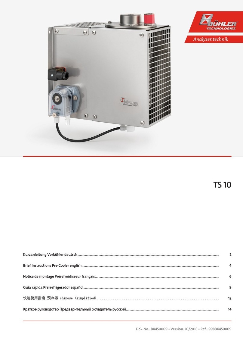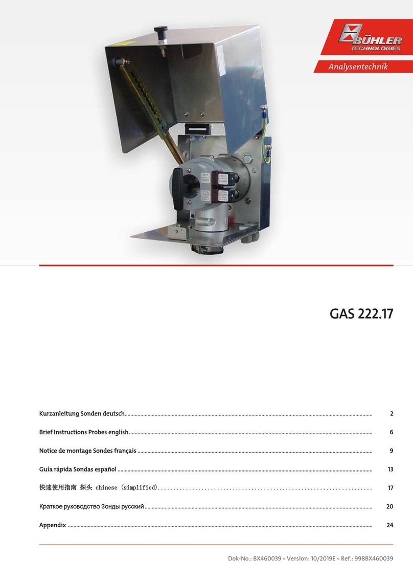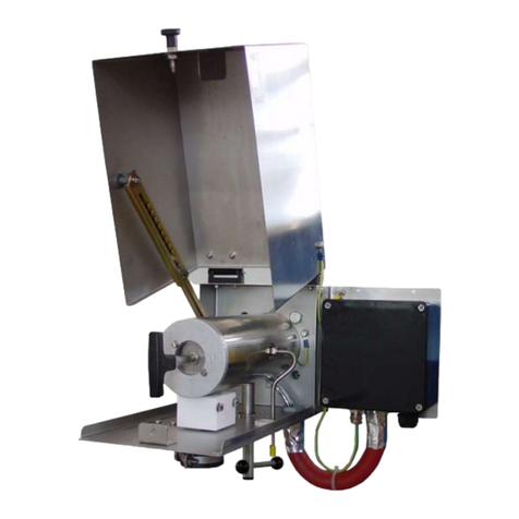
GAS 222.31
Table of Contents
1 Introduction..................................................................................................................................................................................................................... 3
1.1 Intended Use......................................................................................................................................................................................................... 3
1.2 Type Plate............................................................................................................................................................................................................... 3
1.3 Scope of Delivery.................................................................................................................................................................................................. 3
1.4 Ordering Instructions.........................................................................................................................................................................................4
1.5 Product Description............................................................................................................................................................................................ 5
2 Safety instructions.........................................................................................................................................................................................................6
2.1 Important advice .................................................................................................................................................................................................6
2.2 General hazard warnings ................................................................................................................................................................................. 7
3 Transport and storage ..................................................................................................................................................................................................8
4 Installation and connection ........................................................................................................................................................................................9
4.1 Installation site requirements.........................................................................................................................................................................9
4.2 Installing the upstream filter ..........................................................................................................................................................................9
4.3 Insulation...............................................................................................................................................................................................................9
4.4 Connecting the Gas Line....................................................................................................................................................................................9
4.4.1 Blowback Connection........................................................................................................................................................................10
4.4.2 Connecting the Gas Line...................................................................................................................................................................10
4.4.3 Connecting the calibrating gas line (optional)..........................................................................................................................10
4.5 Connecting the Blowback and Pressure Vessel (Optional) ...................................................................................................................10
4.6 Electrical connections .......................................................................................................................................................................................11
4.6.1 Connection via Terminal Strip.........................................................................................................................................................11
4.6.2 Heated Pressure Vessel (Optional) .................................................................................................................................................11
4.6.3 Heated Extension (Optional)............................................................................................................................................................11
5 Operation and Control.................................................................................................................................................................................................12
5.1 Basic function of the probe controller......................................................................................................................................................... 12
5.1.1 Regulator Functions........................................................................................................................................................................... 12
5.1.2 Advanced Functions with Built-In Regulator for Heated Extension (Optional)...............................................................12
5.1.3 Advanced functions for built-in blowback control (optional)............................................................................................... 12
5.1.4 Additional Board for Solenoid Valves and Limit Switches (SV Board Option)..................................................................12
5.2 Use of menu functions .....................................................................................................................................................................................13
5.2.1 Menu Navigation Overview ............................................................................................................................................................14
5.2.2 Detailed description of the operational principle .................................................................................................................... 15
5.3 Description of menu functions ......................................................................................................................................................................15
5.3.1 Main Menu ........................................................................................................................................................................................... 15
5.3.2 Probe Controller Submenu [Display: Prob].................................................................................................................................16
5.3.3 Regulator Submenu for Heated Extension [Display: Adon] (Optional)..............................................................................16
5.3.4 Submenu Blowback control [Display: bbc] (optional) ............................................................................................................. 17
6 Maintenance.................................................................................................................................................................................................................. 18
6.1 Replacing the upstream filter........................................................................................................................................................................ 19
6.2 Inlet filter blowback (within the process stream)................................................................................................................................... 20
6.2.1 Manual Blowback (Without Blowback Control) ....................................................................................................................... 20
6.2.2 Automatic Blowback (External Blowback Control)..................................................................................................................20
6.2.3 Built-In Blowback Control (Optional)............................................................................................................................................ 21
7 Service and repair.........................................................................................................................................................................................................22
7.1 Troubleshooting ................................................................................................................................................................................................22
7.2 Spare Parts and Accessories ...........................................................................................................................................................................23
8 Disposal...........................................................................................................................................................................................................................24
9 Appendices..................................................................................................................................................................................................................... 25
9.1 Technical Data....................................................................................................................................................................................................25
9.2 Flow chart ............................................................................................................................................................................................................ 25
9.3 Dimensions .........................................................................................................................................................................................................26
9.4 Connection Diagram ........................................................................................................................................................................................ 27
9.5 Connection diagram heated pressure vessel............................................................................................................................................28
iBühler Technologies GmbHBE460061 ◦ 09/2021
